TDX (TanDEM-X)
EO
Atmosphere
Ocean
Atmospheric Temperature Fields
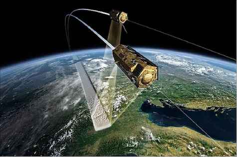
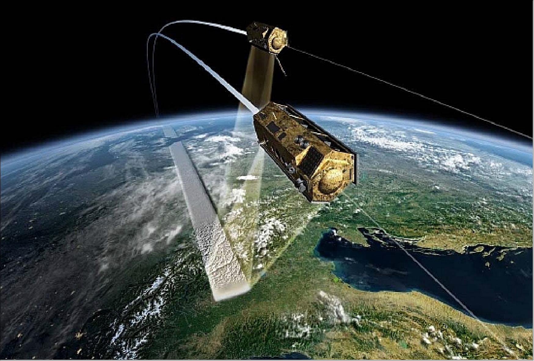
TanDEM-X is an interferometric SAR satellite mission, funded in a public/private collaboration between the German Aerospace Centre (DLR) and Airbus Defence and Space (formerly EADS Astrium GmbH). The satellite launched in June, 2010 and constructs three-dimensional images of Earth’s surface.
Quick facts
Overview
| Mission type | EO |
| Agency | DLR |
| Mission status | Operational (extended) |
| Launch date | 21 Jun 2010 |
| Measurement domain | Atmosphere, Ocean, Land, Snow & Ice |
| Measurement category | Atmospheric Temperature Fields, Multi-purpose imagery (ocean), Multi-purpose imagery (land), Vegetation, Albedo and reflectance, Atmospheric Humidity Fields, Landscape topography, Ocean topography/currents, Sea ice cover, edge and thickness, Snow cover, edge and depth |
| Measurement detailed | Ocean imagery and water leaving spectral radiance, Land surface imagery, Vegetation type, Earth surface albedo, Atmospheric specific humidity (column/profile), Atmospheric temperature (column/profile), Ocean surface currents (vector), Land surface topography, Sea-ice cover, Snow cover, Sea-ice type, Glacier motion, Glacier cover |
| Instruments | X-Band SAR, TOR |
| Instrument type | Imaging microwave radars, Atmospheric temperature and humidity sounders |
| CEOS EO Handbook | See TDX (TanDEM-X) summary |
Related Resources
Summary
Mission Capabilities
TanDEM-X is identical to its twin, TerraSAR-X, and has one X-band Synthetic Aperture Radar that collects high-resolution images for the monitoring of land surfaces and coastal processes, specifically for agricultural, geological, and hydrological applications. The sensor measures a multitude of processes including Albedo and reflectance, landscape topography, multi-purpose imagery of land and ocean, ocean topography and currents, sea ice cover, edge and thickness, snow cover, edge and depth, and vegetation.
TanDEM-X also includes a Tracking, Occultation and Ranging (TOR) payload that consists of a dual-frequency Integrated GPS Occultation Receiver (IGOR) functioning as an independent tracking technique via the Laser Retro Reflector (LRR). There is also a Laser Communications Terminal (LCT) that demonstrates an optical link that is a part of an experimental broadband data relay transmitting 300 Mbit/s from TanDEM-X to the ground segment.
Performance Specifications
The TanDEM-X SAR instrument has multiple modes such as Spotlight, Stripmap and ScanSAR each having a resolution of 1.2m x 1m- 4m, 3m x 3m-6m, and 16m x 16m, respectively. The instrument also has swath widths of 10km (Spotlight), 30km (Stripmap) and 100km (ScanSAR). The HRTE-3 (High-Resolution Terrain Elevation, level-3) model provides the spacecraft with a relative vertical accuracy of 2m where a slope is ≤ 20% and 4m where a slope is ≥20%.
The absolute vertical accuracy is 10m with a spatial resolution of 12m and allows the constellation to produce higher accuracy and resolution than previous generations of elevation models. TDX has a mean altitude of 515km and is in a sun-synchronous orbit with an inclination of 97.44°.
Space and Hardware Components
The TanDEM-X mission is characterised by a close link between space and ground segments and includes three major elements that are covered by the German Space Centre (DLR). These ground segments include the Mission Operations Segment (MOS) that operate the twin satellites (TanDEM-X and TerraSAR-X), the Payload Ground Segment (PGS) that handle increased data volume and receiving stations, adapting processing chains for new data products, and the Instrument Operations and Calibration Segment (IOCS) that operates the two SAR sensors in specific modes provided by the Microwaves and Radar Institute (IHR). Together these stations allow the constellation to accurately record new data and to maintain end-user services such as analysis and volume.
TDX (TanDEM-X: TerraSAR-X add-on for Digital Elevation Measurement)
Spacecraft Launch Mission Status Sensor Complement Ground Segment References
TSX/TanDEM-X is a high-resolution interferometric SAR mission of DLR (German Aerospace Center), together with the partners EADS Astrium GmbH and Infoterra GmbH in a PPP (Public Private Partnership) consortium. The mission concept is based on a second TerraSAR-X (TSX) radar satellite flying in close formation to achieve the desired interferometric baselines in a highly reconfigurable constellation. A contract to build the TanDEM-X spacecraft was signed in September 2006 between DLR and EADS Astrium.
The primary goal of the innovative TanDEM-X/TerraSAR-X constellation is the generation of a global, consistent, timely and high-precision DEM (Digital Elevation Model), corresponding to the HRTE-3 (High-Resolution Terrain Elevation, level-3) model specifications (12 m posting, 2 m relative height accuracy for flat terrain). The HRTE-3/HRTI-3 models were defined by NGA (National Geospatial-Intelligence Agency), Washington, D. C. 1) 2) 3) 4) 5) 6) 7) 8) 9)
The achievable DEM height accuracy has been confirmed in Phase A by a detailed performance analysis taking into account all major system and scene parameters like the finite radiometric sensitivity of the individual radar sensors, co-registration and processing errors, range and azimuth ambiguities, baseline and Doppler decorrelation, the strength and orientation of surface and vegetation scattering, quantization errors, temporal and volume decorrelation, baseline estimation errors and the chosen independent post-spacing (horizontal resolution). 10) 11)
For generating the global DEM, roughly 300 TByte of raw data will be acquired using a network of ground receiving stations. Processing DEM products requires advanced multi-baseline techniques and involves mosaicking and a sophisticated calibration scheme on a continental scale.
Beyond its primary mission objective of generating a global HRTI-3 DEM, TanDEM-X provides a configurable SAR interferometry platform for demonstrating new SAR techniques and applications, such as digital beamforming, single-pass polarimetric SAR interferometry, ATI (Along-Track Interferometry) with varying baseline, or super-resolution. Close formation flight collision avoidance becomes a major issue and a new orbit concept based on a double helix formation has been developed to ensure a safe orbit separation.
Overview
In the time frame of 2007, the global coverage with topographic data at sufficiently high spatial resolution is inadequate or simply not available for scientific and governmental use. The first step to meet the requirements of the scientific community for a homogenous, highly reliable DEM with DTED-2 specifications was SRTM (Shuttle Radar Topography Mission), launch on Feb. 11, 2000. SRTM, representing the first spaceborne single-pass interferometer, was built by supplementing the Shuttle Imaging Radar-C/X-Synthetic Aperture Radar system by second receive antennas mounted at the tip of a 60 m deployable mast structure.
Within a ten-day mission, SRTM collected interferometric data for a near-global DTED-2 (Digital Terrain Elevation Data Level 2) land surface coverage. DTED-2 is the current basic high-resolution elevation data source for all military activities and civil systems that require landform, slope, elevation, and/or terrain roughness in a digital format. DTED-2 is a uniform gridded matrix of terrain elevation values with post spacing of one arc second (approximately 30 m). SRTM mapped the Earth between 60 N and 56 S; however, there are still wide gaps, in particular at the lower latitudes.
The TanDEM-X/TerraSAR-X (TDX/TSX) constellation has the potential to close these gaps, to fulfil the requirements of a global homogeneous and high-resolution coverage of all land areas thereby providing the vital information for a variety of applications. The high-precision DEM models are of utmost interest for the civil and military communities, representing the basis for all modern navigation applications.
Parameter | Specification | HRTI-3 definition | DTED-2 |
Relative vertical accuracy | 90% linear point-to-point error over a 1º x 1º cell | 2 m (slope ≤ 20%) | 12 m (slope < 20%) |
Absolute vertical accuracy | 90% linear error | 10 m | 18 m |
Relative horizontal accuracy | 90% circular error | 3 m | 15 m |
Horizontal accuracy | 90% circular error | 10 m | 23 m |
Spatial resolution | Independent pixels | 12 m (1 arcsec) | 30 m (1 arcsec) |
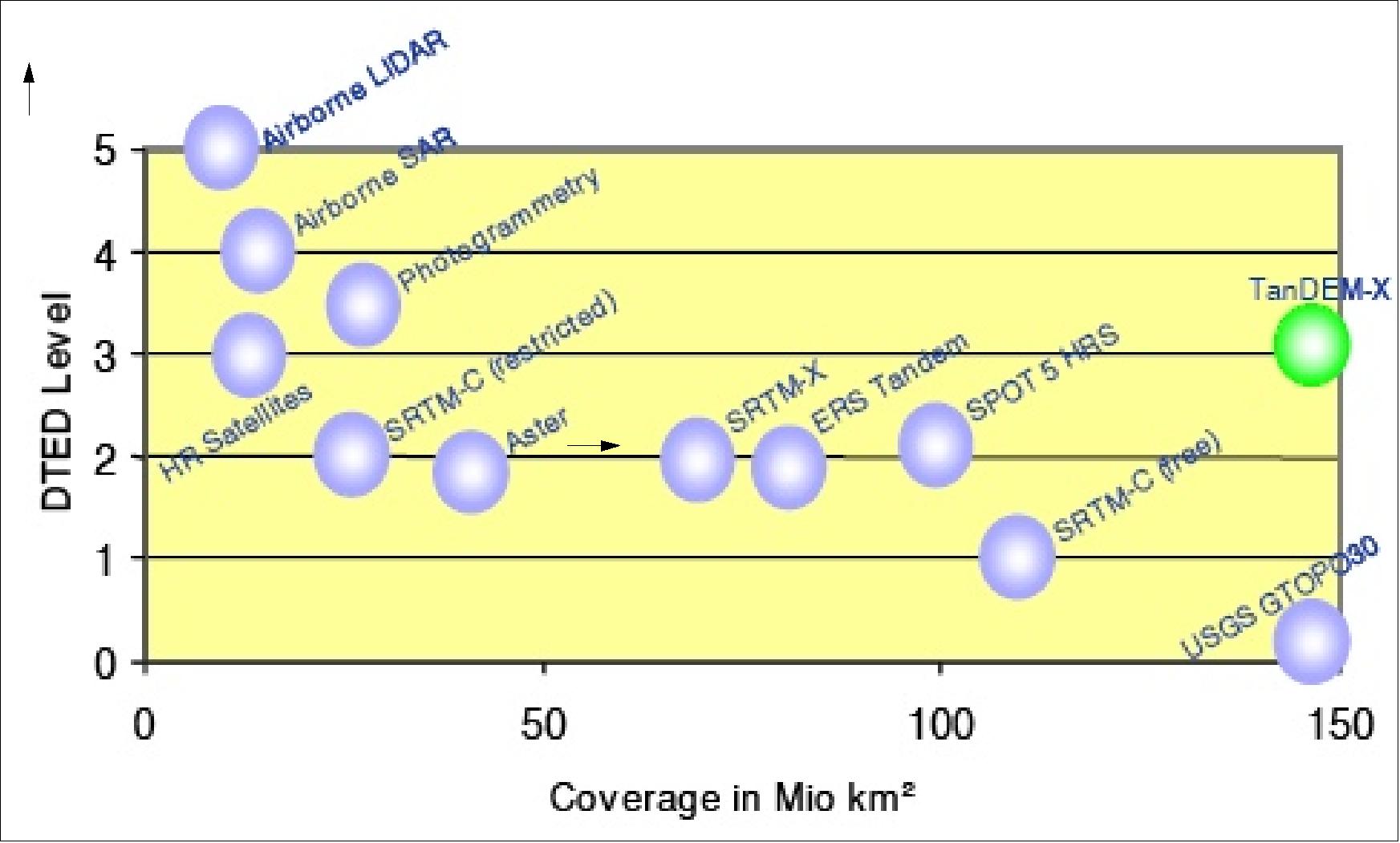
Figure 1 gives an overview of DEM-level coverage estimates of various observation technologies in the different HRTI classes. It should be noted that a surface area of 150 x 106 km2 represents a global coverage of Terra Firma (i.e., all land areas).
Mission Concept
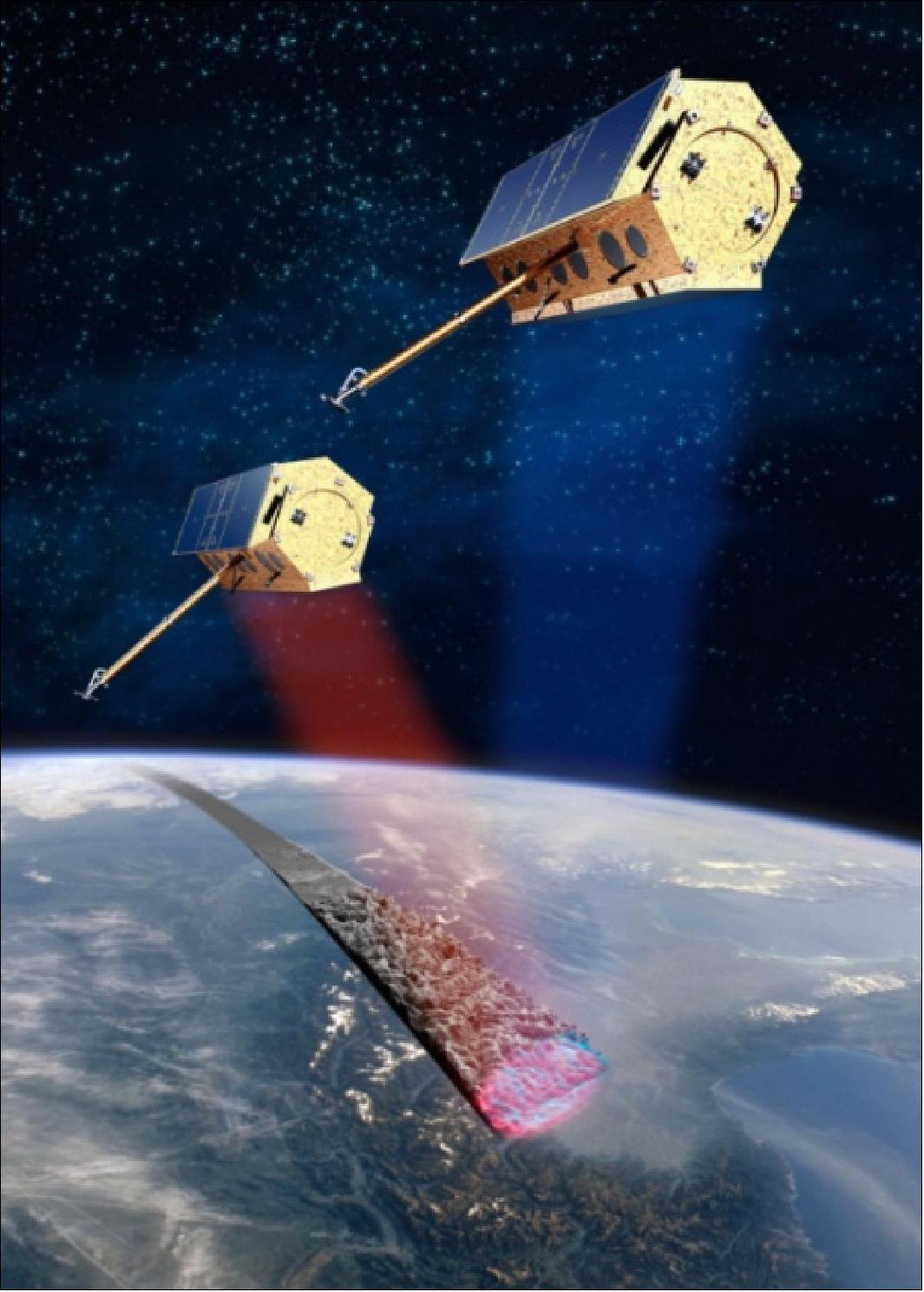
The TanDEM-X mission concept is based on an extension of the TerraSAR-X mission by a second almost identical satellite, namely TanDEM-X. Flying the two satellites in a close formation with typical cross-track distances of 300-500 m provides a flexible single-pass SAR interferometer configuration, where the baseline can be selected according to the specific needs of the application. 12) 13) 14) 15) 16) 17) 18) 19) 20) 21) 22) 23)
The SAR (Synthetic Aperture Radar) instruments of TerraSAR-X and TanDEM-X are fully compatible, both offer transmit and receive capabilities along with polarimetry. These features provide maximum flexibility in supporting operational services (acquisition of highly accurate cross-track and along-track interferograms without the inherent accuracy limitations imposed by repeat-pass interferometry) and in data product quality.
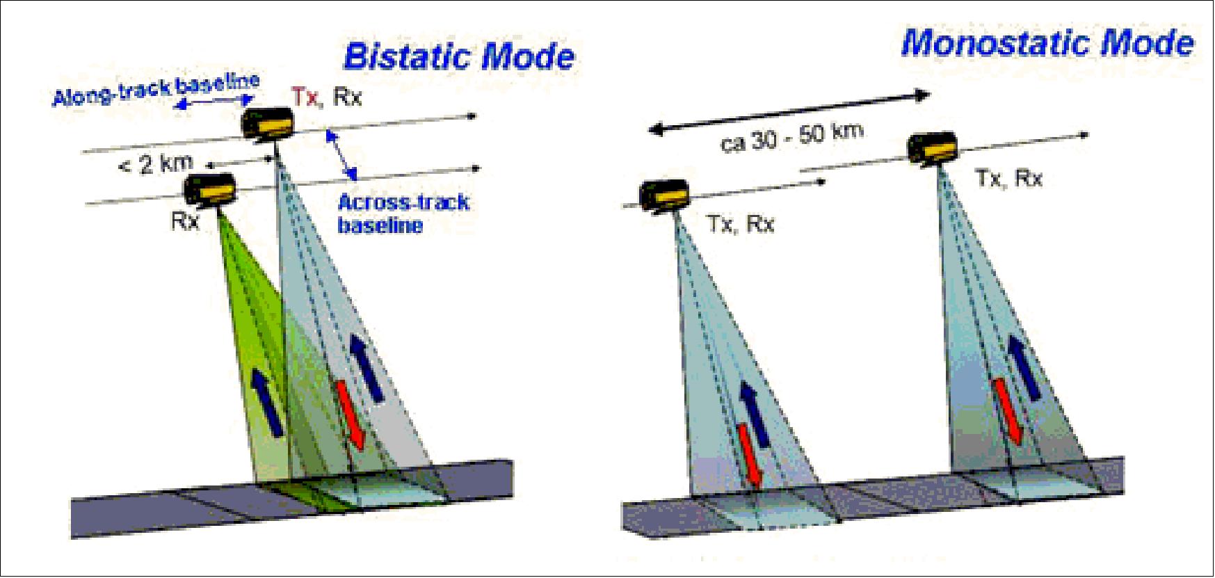
The following basic interferometric SAR (InSAR) observational modes are available (Figures 2 and -3):
1) Bistatic mode where the SAR instruments of both spacecraft look into a common footprint thus providing different views of the observed target area
(Note: bistatic InSAR is characterized by the simultaneous measurement of the same scene and overlapping Doppler spectra with 2 receivers, avoiding temporal decorrelation; PRF synchronization and relative phase referencing between the satellites are mandatory).
- One satellite serves as a transmitter and both satellites record the scattered signal simultaneously. In this tandem configuration, both spacecraft fly in a close orbit formation. The baseline of this configuration can be selected according to the specific needs of the application. This enables the acquisition of highly accurate single-pass cross-track and/or along-track interferograms without the inherent accuracy limitations imposed by repeat-pass interferometry due to temporal decorrelation and atmospheric disturbances.
2) Pursuit monostatic mode where both satellites are operated independently avoiding the need for synchronization; hence, both SAR instruments look to acquire data from the same swath with a short time difference of a few seconds corresponding to an along-track distance of 30-50 km.
Different to conventional repeat-pass (i.e., two‐pass or multi‐pass) InSAR observations, the temporal decorrelation is still small for most terrain types except for ocean surfaces and vegetation in the case of moderate to high wind speeds.
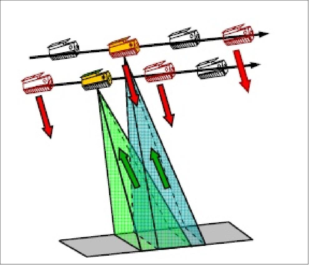
3) Alternating bistatic mode is similar to bistatic mode, but the transmitter is switched from pulse to pulse between the two satellites.
The baseline for operational DEM generation is the bistatic mode which minimizes temporal decorrelation and uses efficiently the transmit power. This mode uses either TSX or TDX as a transmitter to illuminate a common radar footprint on the Earth's surface. The scattered signal is then recorded by both satellites simultaneously. This simultaneous data acquisition makes dual use of the available transmit power and is mandatory to avoid possible errors from temporal decorrelation and atmospheric disturbances.
The alternating bistatic mode can be used for phase synchronization, system calibration, and to acquire interferograms with two different phase-to-height sensitivities; the simultaneously acquired monostatic interferogram has a higher susceptibility to ambiguities, especially at high incident angles.
A mission concept has been developed which enables the acquisition/generation of a global DEM within three years. This concept includes multiple data takes with different baselines, different incidence angles, and data takes from ascending and descending orbits to deal with difficult terrain like mountains, valleys, tall vegetation, etc.
The TanDEM-X mission concept allocates also sufficient acquisition time and satellite resources to secondary mission objectives which cover the following application spectrum:
• Moving target indication with a distributed four aperture displaced phase centre system
• The measurement of ocean currents and the detection of ice drift by along-track interferometry
• High-resolution SAR imaging based on a baseline-induced shift of the Doppler and range spectra (super-resolution)
• The derivation of vegetation parameters with polarimetric SAR interferometry
• Large baseline bistatic SAR imaging for improved scene classification, as well as localized very high-resolution DEM generation based on spotlight interferometry.
• Demonstration of high-resolution wide-swath SAR imaging with four-phase-center digital beamforming.
In short, the TanDEM-X mission concept encompasses enabling technologies in a number of ways, including the first demonstration of a bistatic interferometric satellite formation in space, as well as the first close formation flight in operational mode. Several new SAR techniques will also be demonstrated for the first time, such as digital beamforming (DBF) with two satellites, single-pass polarimetric SAR interferometry, as well as single-pass along-track interferometry with varying baseline. 24)
TanDEM Orbits
Close formation flight of TerraSAR-X and TanDEM-X. The TerraSAR-X spacecraft remains in its sun-synchronous dawn-dusk orbit with the following parameters: mean altitude of 515 km, inclination = 97.44º, local equatorial crossing time at 18 hours on the ascending node, nominal revisit period of 11 days (167 orbits in the repeat, 15 2/11 orbits/day. 25) 26) 27) 28) 29) 30) 31)
For setting up the effective baseline, TanDEM-X is separated from TerraSAR-X in the right ascension of the ascending node. This will span a horizontal baseline, which will be adjusted between 200 m and 3000 m to achieve the effective baselines required for DEM acquisition at different latitudes. An additional vertical separation at the northern and southern turns is achieved by a relative shift of the eccentricity vectors of the satellites.
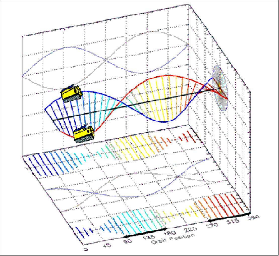
The result is a complete separation of the two satellite orbits called Helix-formation, which enables a safe operation of close formations with minimum collision risk. Such a Helix formation with an offset in eccentricity vectors and a separation in the right ascension of the ascending node is shown in Figure 2.
The TanDEM-X operational scenario requires a coordinated operation of two satellites flying in close formation. Several options have been investigated and the Helix satellite formation has finally been selected. The helix configuration allows for maintaining a relatively small distance between both satellites while at the same time avoiding the collision risk at the poles. This formation combines an out-of-plane orbital displacement (e.g. by different ascending nodes) with a radial (vertical) separation (e.g. by different eccentricity vectors) resulting in a helix-like relative movement of the satellites along the orbit. Since there exists no crossing of the satellite orbits, it is now possible to arbitrarily shift the satellites along their orbits, e.g. to adjust very small along-track baselines at predefined latitudes and to allow safe spacecraft operation without autonomous control.
The Helix orbit for close formation flight, involving the maintenance of baselines of a cluster of spacecraft in orbit for cross-track and along-track interferometric observations, has been patented by DLR. The inventors are: Alberto Moreira, Gerhard Krieger, and Josef Mittermayer.
1) European Patent Office, Patent No: EP 1 273 518 A2 of Jan. 8, 2003. Title: “Satellitenkonfiguration zur interferometrischen und/oder tomographischen Abbildung der Erdoberfläche mittels Radar mit synthetischer Apertur.”
2) US Patent No: US 6,677,884 B2 of Jan. 13, 2004. Title: “Satellite Configuration for Interferometric and/or Tomographic Remote Sensing by Means of Synthetic Aperture Radar (SAR).”
The HELIX formation enables complete coverage of the Earth with a stable height of ambiguity by using a small number of formations (e.g. ΔΩ ={300 m, 400 m, 500 m} and Δe ={300 m, 500 m}, where `Ω' is the right ascension of the ascending node, and `e' is the eccentricity. Baseline fine tuning can be achieved by taking advantage of the natural rotation of the eccentricity vectors due to secular disturbances and fixing the eccentricity vectors at different relative phasings. Since there exists no crossing of the satellite orbits, it is possible to arbitrarily shift the satellites along their orbits, e.g. to adjust very small along-track baselines at predefined latitudes and to allow safe spacecraft operation without autonomous control.
An appropriate reference scenario has been derived which enables one complete coverage of the Earth with baselines corresponding to a height of ambiguity of ca. 35 m within 1 year assuming a bistatic acquisition in stripmap mode with an average acquisition time of 140 s per orbit.
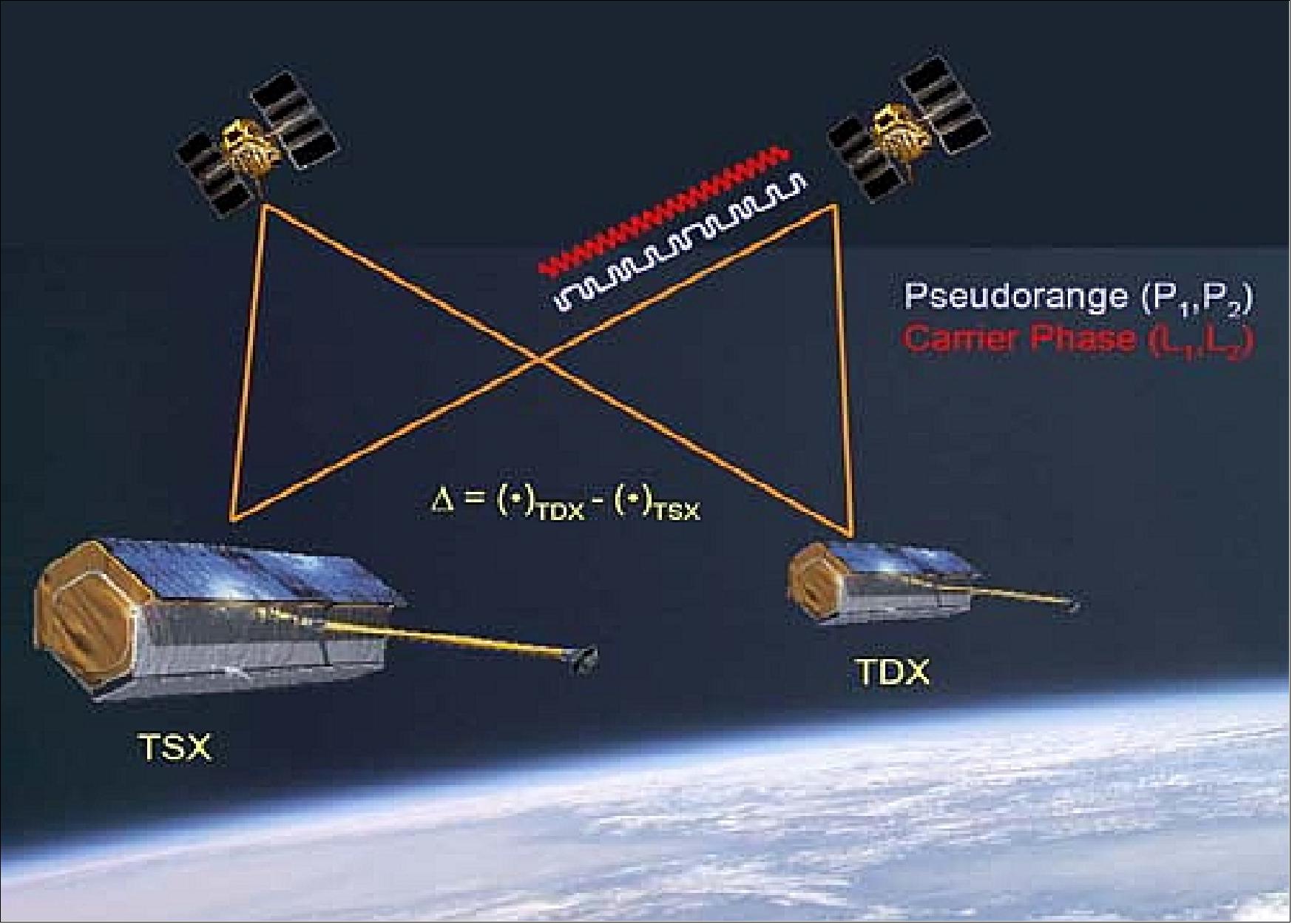
Both high precision orbit determination (POD) and interferometric baseline vector determination of the tandem configuration will be accomplished using the GPS-based TOR (Tracking, Occultation and Ranging) device, a dual-frequency receiver, which will be provided by GFZ as for TerraSAR-X.
Coarse orbit control and maintenance of the tandem configuration will be done as part of the regular maintenance maneuvers using thrusters. Fine-tuning of the Helix of the TanDEM-X satellite will be performed using additional cold gas thrusters.
TanDEM-X formation flight: The Helix formation geometry implies maximum out-of-plane (cross-track) orbit separation at the equator crossings and maximum radial separation at the poles. This is realized by small ascending node differences and by slightly different eccentricity vectors, respectively, as depicted in Figure 7. This concept of relative eccentricity/inclination vector separation results in a Helix-like relative motion of the satellites along the orbit and provides a maximum level of passive safety in case of a vanishing along-track separation. 32)
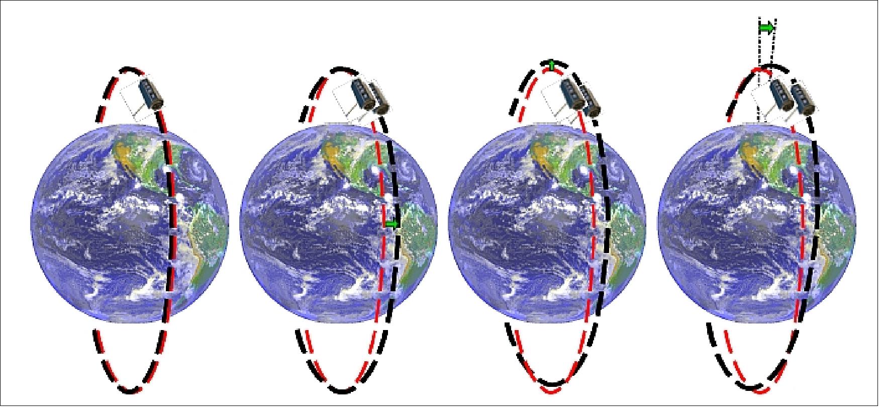
Legend to Figure 7: From left to right: (1) identical orbits, (2) maximum horizontal separation at equator crossings by a small offset in the ascending node (green arrow), (3) a small eccentricity offset causes different heights of perigee/apogee and hence yields a maximum radial separation at the poles. (4) Optional rotation of the argument of perigee to achieve larger baselines at high latitude regions.
Spacecraft
During the development phase of the TerraSAR-X spacecraft, the TanDEM-X mission concept became a vision. However, a realization of the vision of two SAR missions in orbit could only have a chance with a necessary minimum extension of the SAR design on TerraSAR-X to support the synchronized operation of both radars. 'Minimum' meant that the TerraSAR-X schedule was not endangered and was further constrained to allow a cost-effective 1:1 rebuild approach for the SAR on TanDEM-X. 33)
For the spacecraft bus, the approach was constrained by only allowing software changes on TerraSAR-X. The bus design on TanDEM-X was extended to allow the formation flight of both satellites - with TanDEM-X as the 'Master of the Constellation.' Particularly the bus hardware extensions were constrained by the tight schedule leading to a strong orientation on existing hardware designs. The software changes are being verified during the TanDEM-X on-ground tests and will be uplinked to TerraSAR-X in preparation for the constellation flight.
Like the TerraSAR-X (TSX) satellite, the TanDEM-X (TDX) satellite is based on a mission-tailored AstroBus service module and a radar instrument developed according to the AstroSAR concept. The main differences to the TerraSAR-X satellite are the more sophisticated cold gas propulsion system to allow for constellation control, the additional S-band receiver to enable the reception of status and GPS position information broadcasted by TerraSAR-X, and the X-band inter-satellite link for phase referencing between the TSX and TDX radars (the required modifications on the TSX spacecraft have already been implemented).
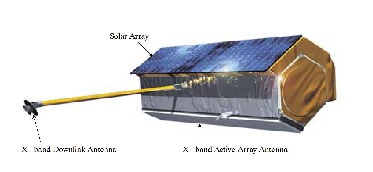
The outer shape of the spacecraft is mainly driven by the accommodation of the X-band radar instrument, the body-mounted solar array and the geometrical limitations given by the Dnepr-1 launcher fairing. A standard S-band TT&C system with full spherical coverage in uplink and downlink is used for satellite command reception and telemetry transmission.
An additional inter-satellite S-band receiver, operating at the TerraSAR-X downlink frequency, will allow for the reception of status and GPS position information broadcasted by TerraSAR-X. It provides a 1-way link with which TanDEM-X can receive real-time position and velocity data from TerraSAR-X from its nominal 1-frequency GPS receiver. The TanDEM-X OBC (On-Board Computer) software uses such data from both satellites to generate a collision warning flag. Furthermore, this data is used by the TAFF (TanDEM-X Autonomous Formation Flying) algorithm running on the OBC (see Ref. 37).
Nominally, formation flying will be under ground control. The TAFF algorithm will be tested open-loop during the commissioning phase and could then become the standard approach for the constellation phases. The ISLR (Intersatellite Link Receiver) is laid out to receive the TerraSAR-X S-band transmissions in low power mode. It is cold redundant with each receiver/decoder cross-strapped to two patch antennas. This layout keeps contact gaps to less than 15 minutes in addition to an interruption imposed by the nominal high rate S-band contact with the ground station.
The OBC is a fully redundant unit that aims at performing the onboard data handling and the attitude and control functions on the satellites. The processor module is based on the ERC32, clocked at 40 MHz, and ensures the execution of software with a processing capability of more than 10 MIPS. The internal RAM comprises 6 MByte, with 4 MByte used nominally and 2 MByte reserved for the implementation of a cold redundancy.
The TanDEM-X attitude control system is based on reaction wheels for fine-pointing with magnet torquers for wheel de-saturation. A combined hydrazine/cold-gas propulsion system allows for orbit maintenance and rapid rate damping during initial acquisition. Attitude and orbit measurement is performed with a GPS/Star Tracker system during nominal operation and a CESS (Coarse Earth and Sun Sensor) in safe mode situations and during the initial acquisition. A combination of laser gyro and magnetometer allows for rate measurements in all mission phases.
CGS (Cold Gas Propulsion System): The CGS on TanDEM-X is of CryoSat-2 heritage and uses a high-pressure tank of nitrogen gas. This provides small thruster impulses fitting the needs for constellation flight. There are 2 redundant branches each culminating in 2 redundant pairs of thrusters mounted on the satellite in each of the ± flight directions. A formation flight maneuver involves the operation of a pair of thrusters in one of these directions.
The TanDEM-X spacecraft has a launch mass of about 1340 kg (payload mass of 400 kg); the nominal design life is five years after the end of the commissioning phase (estimated to be 3 months); the satellite consumables will last for 6.5 years after commissioning.
The Public-Private Partnership (PPP) between DLR and EADS Astrium has been extended to cover the design, build, launch, commissioning and operation of the TanDEM-X spacecraft. Like TerraSAR-X, TanDEM-X is a dual-purpose (scientific and commercial) Earth observation mission, providing its data services to the science (DLR) and the non-science communities (Infoterra). This shared approach makes the program affordable to all parties of interest.
Launch
The TanDEM-X spacecraft was launched successfully on June 21, 2010, on a Dnepr-1 launch vehicle with a 1.5 m long fairing extension. The launch provider is ISC Kosmotras, the launch site is the Baikonur Cosmodrome, Kazakhstan. 34) 35)
RF communications: A standard S-band TT&C system with 360º coverage in uplink and downlink is used for satellite command reception and housekeeping telemetry transmission. The uplink path is encrypted. Generated payload (SAR) data are stored onboard in a SSMM (Solid State Mass Memory) unit of 768 Gbit EOL capacity before transmission via the XDA (X-band Downlink Assembly) at a data rate of 300 Mbit/s. The X-band downlink is encrypted.
The on-board SAR raw data are compressed using the BAQ (Block Adaptive Quantization) algorithm, a standard SAR procedure. The compression factor is selectable between 8/6, 8/4, 8/3 or 8/2 (more efficient techniques can only be applied to processed SAR imagery). Both communication links are designed according to the ESA CCSDS Packet Telemetry Standard.
Spacecraft | Rebuild of the TerraSAR-X satellite which was based on the Astrium Flexbus concept and extensive heritage from the CHAMP and GRACE missions |
Features | - X-band downlink horn antenna is mounted at the tip of a 3.3 m long boom |
Spacecraft launch mass | 1340 kg (spacecraft: 1220 kg, fuel: 120 kg) |
Spacecraft size | 5 m length, 2.4 m diameter (hexagonal cross-section) |
Spacecraft design life | 5 years nominal (after the end of the commissioning phase) |
RF communications | - X-band of 300 Mbit/s link of payload data downlink with DQPSK modulation; |
Primary payload | - TDX-SAR instrument is identical to the TSX-SAR (TerraSAR-X SAR instrument) |
TAFF (TanDEM-X Autonomous Formation Flying)
TAFF is a navigation and formation flying software package developed at DLR/GSOC. The overall objective of TAFF is to ease ground and space operations. Its accurate orbit control performance facilitates the synchronization of the two SAR systems via dedicated horns. The positions of the satellites will be known with good precision well in advance of real operations. TAFF will enable a safe and robust formation control with minimum collision risk. 37) 38) 39)
On top of ensuring a stable and more precise baseline for SAR interferometry, TAFF will enhance the exploitation of along-track interferometry techniques. Along-track interferometry is enabled by a special configuration of the formation which provides dedicated osculating along-track separations at desired locations along the orbit. This method improves the detection, localization and signal ambiguity resolution for ground-moving targets and can be used for traffic monitoring applications.
Furthermore, real-time collision risk assessments will be performed by TAFF on a routine basis to support automated FDIR (Fault Detection Isolation and Recovery) tasks.
Two GPS receivers are installed on each spacecraft. The dual-frequency IGOR GPS receiver of BroadReach Inc., which serves exclusively scientific purposes, and the single-frequency MosaicGNSS receiver of EADS Astrium, whose navigation data are used by TAFF.
A one-way inter-satellite link (ISL) is being implemented between the two satellites, using the existing S-band downlink system on TSX and an additional receiver on TDX. The link is designed to function properly up to distances of a few km (ca. 2-5 km).
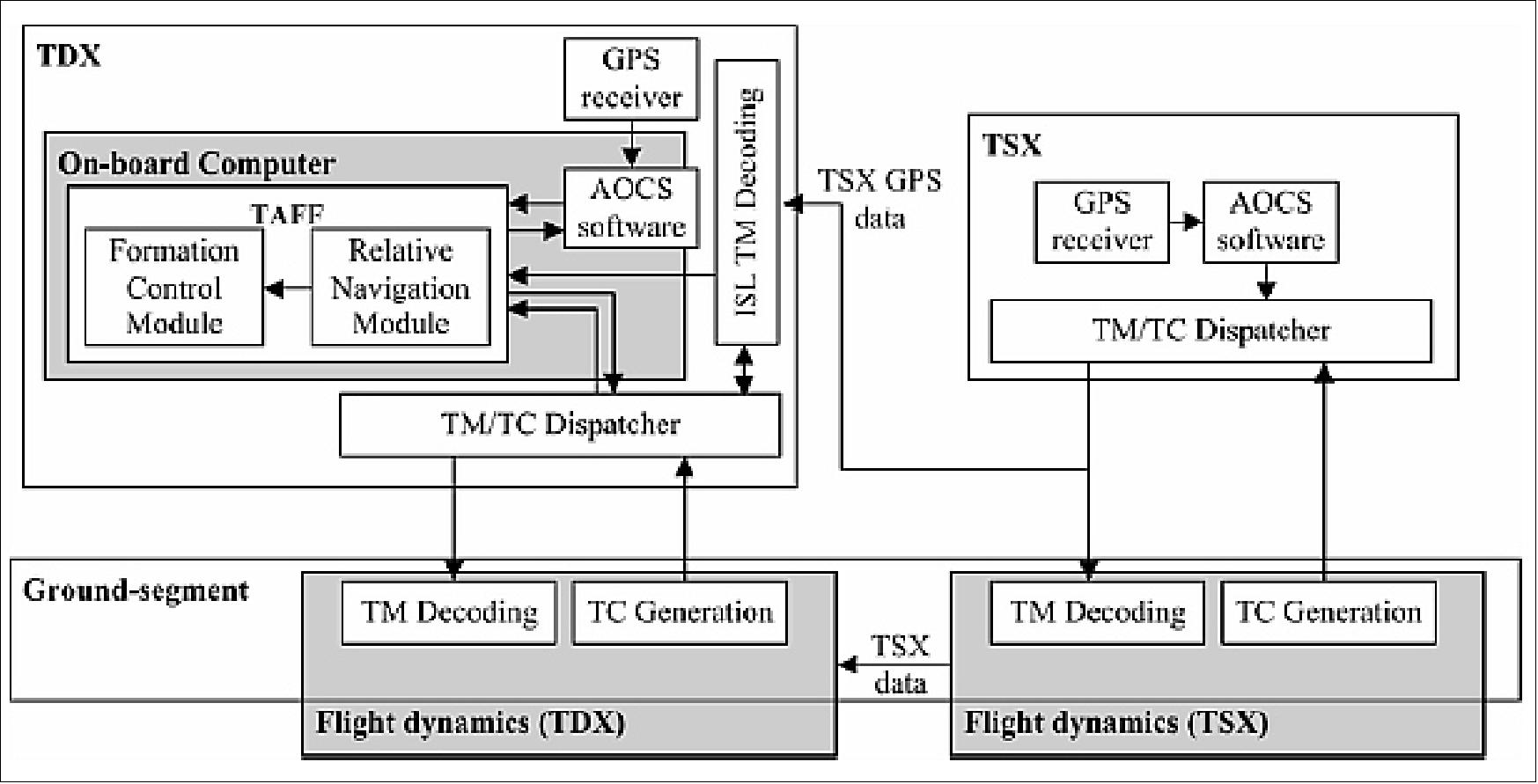
The TAFF software package resides in the OBC of the TDX spacecraft. TAFF gets as inputs the GPS data provided by the GPS receiver onboard TDX and, through the ISL, also from the GPS receiver data onboard the TSX. TAFF uses the CGS (Cold Gas Propulsion System) to control the formation and performs in-plane control maneuvers in the flight and anti-flight directions only.
Inflight performance test of TAFF 40)
The in-flight performance validation of the experimental autonomous formation-keeping system embarked by the German TanDEM-X formation has been performed during a 12-day-long closed-loop campaign conducted in June 2012. Relative control performance better than 10 m was achieved, demonstrating that a significant gain of performance can be achieved when the control of the formation is done autonomously on-board instead of on-ground. Furthermore, the formation-keeping system was shown to be operationally robust, easy to operate and fully predictable, i.e. fully suited for routine mission operations.
This campaign concludes successfully a series of validation activities, opening new doors to future innovative scientific TanDEM-X experiments for which enhanced formation control is required.
TAFF is the first onboard autonomous formation-keeping system ever employed on a high-cost scientific formation flying mission with routine data acquisition. As such, it has to face inherent natural fears and reluctance to rely on onboard autonomy for critical activities like formation maintenance. TAFF aims at making evolving the minds by proving that a proper design of the formation (passively safe), as well as a smart implementation of the onboard navigation software (robust navigation and control, internal safety mechanisms), can guarantee simple, accurate and safe formation keeping.
Parameter / Instrument | MosaicGNSS (EADS Astrium) | IGOR (BroadReach Inc.) |
GPS tracking capability | 8 channels L1 | 16 x 3 channels L1/L2 |
Raw data | C/A: 5 m | C/A, P(Y) 0.2 m |
Power consumption | 10 W | 15 W |
Radiation tolerance | 35 krad | 12 krad |
Formation Flight and Safety Measures
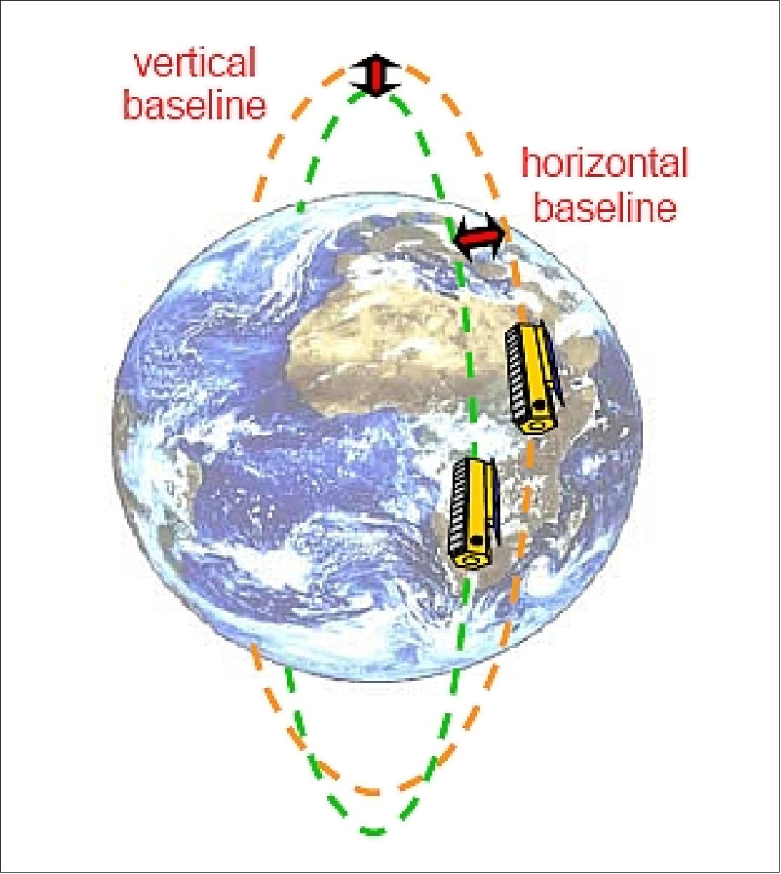
The requirement of a configurable close formation between TSX and TDX arises from the need for a SAR interferometer in space. The satellites fly in almost identical orbits whereby the position of TDX describes a helix around the trajectory of TSX. This is achieved by the separation of the relative eccentricity and inclination vector. The maximal radial separation is reached over the poles (vertical baseline typically between 200 - 500 m) and the maximum separation in normal direction occurs at the equator (horizontal baseline typically 200 – 500 m; see Figure 5).
In this way, it can be assured that the radial and normal separation never become zero at the same time. The shape of the helix depends upon the mission phase. The formation with the smallest baseline had a minimum separation of 150 m. Orbit correction maneuvers are carried out with the hydrazine propulsion system simultaneously on both spacecraft with the same ΔV. Additionally, formation-keeping maneuvers are needed to compensate the drift of the relative e-vector that arises from the J2-perturbation (Ref. 31). These maneuvers are made only on TDX with the cold gas system. 41) 42)
Thrusters were originally planned to be the prime actuators during non-nominal situations in AOCS safe mode. The experience with TSX showed, however, that the design with the thrusters mounted at the back of the satellite is far from ideal for flight in close formation. Analyses showed a collision risk of 1/500 due to orbit changes in case of a drop to the thruster-based safe mode. 43)The reason is that just a minor part of the thrust is available for attitude control, whereas the major part is unpredictably changing the orbit.
- Hence, the second type of safe mode was implemented with to control the attitude without changing the orbit. The so-called ASM-MTQ (Acquisition and Safe Mode-Magnetorquer) only uses the magnetic torque rods as actuators, whereas it still relies on CESS, magnetometer and IMU as sensors, just like the original ASM-RCS (Acquisition and Safe Mode-Reaction Control System).
However, the damping of the rotation rates and the recovery of the attitude takes longer in ASM-MTQ than in ASM-RCS due to the weakness of the magnetic field at 514 km altitude. The maximum overall body rate that can be handled is 0.5º/s due to the concept that the torque rods and the magnetometers are operated in alternation to allow disturbance-free measurements of the Earth’s magnetic field.
The new FDIR (Fault Detection, Isolation and Recovery) design intends to always use the magnetorquer-based safe mode first when a severe anomaly has been detected. There are performance limitations in ASM-MTQ as mentioned above, and it might still become necessary to make use of the conventional but more powerful ASM-RCS. The latter will only be used if the continuation of the mission is seriously endangered.
A possible scenario would be the battery voltage dropping below a certain value, a star tracker getting too hot or non-convergence of the attitude after three orbits. The thruster on-time is limited at first instance to make sure that the generated ΔV cannot lead to a collision of the satellites. A reboot of the on-board computer will follow in the worst-case scenario when despite limited use of the thrusters, no convergence was reached. The spacecraft will come up after the reboot in ASM-MTQ again, but this time with wider power/thermal limits.
However, the described sequence will be tried only once. If there is still no convergence or the power/thermal limits are yet violated, the spacecraft will be sent by FDIR to ASM-RCS once more, but this time without limitations to the thruster on time. 44)
The ISL (Inter-Satellite Link) is also used for surveillance but is subject to some limitations. In the first place, the link only works in one direction and in the second, the connection is interrupted anytime the transmitter of TSX or TDX is switched to high-rate for ground station contacts. Therefore it is seen more as an extra safety rather than the part to rely on completely. The ISL is used to transmit some essential parameters of TSX (including GPS position and velocity) to TDX to feed TAFF algorithms (Tandem Autonomous Formation Flight).
AOCS surveillance: The most vital AOCS parameters, such as sensor performance, attitude errors, actuator commands, etc. are monitored on-board. In case of severe anomalies, FDIR can react immediately and switch to the redundant hardware. During ground station contacts, a large number of parameters are checked in the mission control system against pre-defined limit settings and violations are indicated by yellow or red flags. The dump files (data covering also the time span between ground station contacts) are screened with the same limit settings, and violations are reported by email. The events will subsequently be analyzed and it is then decided if they can be disregarded or if a threat to the satellite is developing.
Mission Status
• January 25, 2022: The TanDEM-X mission is operating nominally providing SAR imagery in its 12th year on orbit. Despite being well beyond its mission design life, the satellite is fully functional; it has enough consumables for a mission life until at least 2026. 45)
• June 10, 2021: The German Aerospace Center (DLR) celebrated the eleventh anniversary of its satellite receiving facility in Inuvik, Canada, in a virtual event with international partners. The Inuvik station, which is strategically located within the Arctic Circle, plays a crucial role in receiving data from Earth observation satellites, including the German TanDEM-X mission and the European Copernicus program. The event highlighted the long-standing cooperation between DLR and Canadian institutions like the Canada Centre for Mapping and Earth Observation (CCMEO) and the Canadian Space Agency (CSA).
Since its inception, the Inuvik station has received data from over 30,000 satellite overpasses and has become a vital part of global Earth observation efforts. The station's location in the far north, along with its technological capabilities, makes it a strategic site for both governmental and commercial satellite operations. The event also marked the 50th anniversary of Canadian-German scientific and technological cooperation. 46)
![Figure 13: Photo of the ISSF (Inuvik Satellite Station Facility) in Arctic Canada [image credit: DLR(CC BY-NC.ND 3.0)]](https://eoportal.org/ftp/satellite-missions/t/TanDEMX_250122/TanDEMX_Auto50.jpeg)
• February 13, 2021: The TSX (TerraSAR-X) and TanDEM-X satellites are operating as expected, with enough fuel to continue their mission until at least 2026. Between September 2017 and June 2020, the TanDEM-X mission conducted observations to create a new Digital Elevation Model (DEM) of Earth's land surface. The analysis revealed significant changes in elevation within short periods, highlighting the Earth's dynamic surface, including glaciers, permafrost, forests, and human activities. Consequently, the entire landmass was re-mapped to produce an updated "Change DEM," which became available for commercial and scientific use in mid-2021. Since June 2020, the satellites have focused on further scientific observations, particularly in studying the cryosphere, biosphere, and urban environments. 47)
• December 17, 2020: Since December 2010, the twin satellites TerraSAR-X and TanDEM-X have operated together as a radar interferometer, capturing Earth's surface in three dimensions. This partnership has greatly enhanced imaging capabilities, exemplified by their detailed observation of the Lena Delta in Russia. The delta, with its 1500 small, constantly shifting islands due to sediment deposition, was previously depicted in two dimensions at a single elevation (as depicted in black-and-white in Figure 14). Thanks to TanDEM-X, these elevation differences are now visualized with a vertical accuracy better than two meters. By mid-2016, a precise 3D elevation model of Earth's entire landmass had been created, and the satellites are now collecting data for a second global elevation model, the 'Change DEM,' which documents dynamic changes such as glacier melting and deforestation in three dimensions. 48)
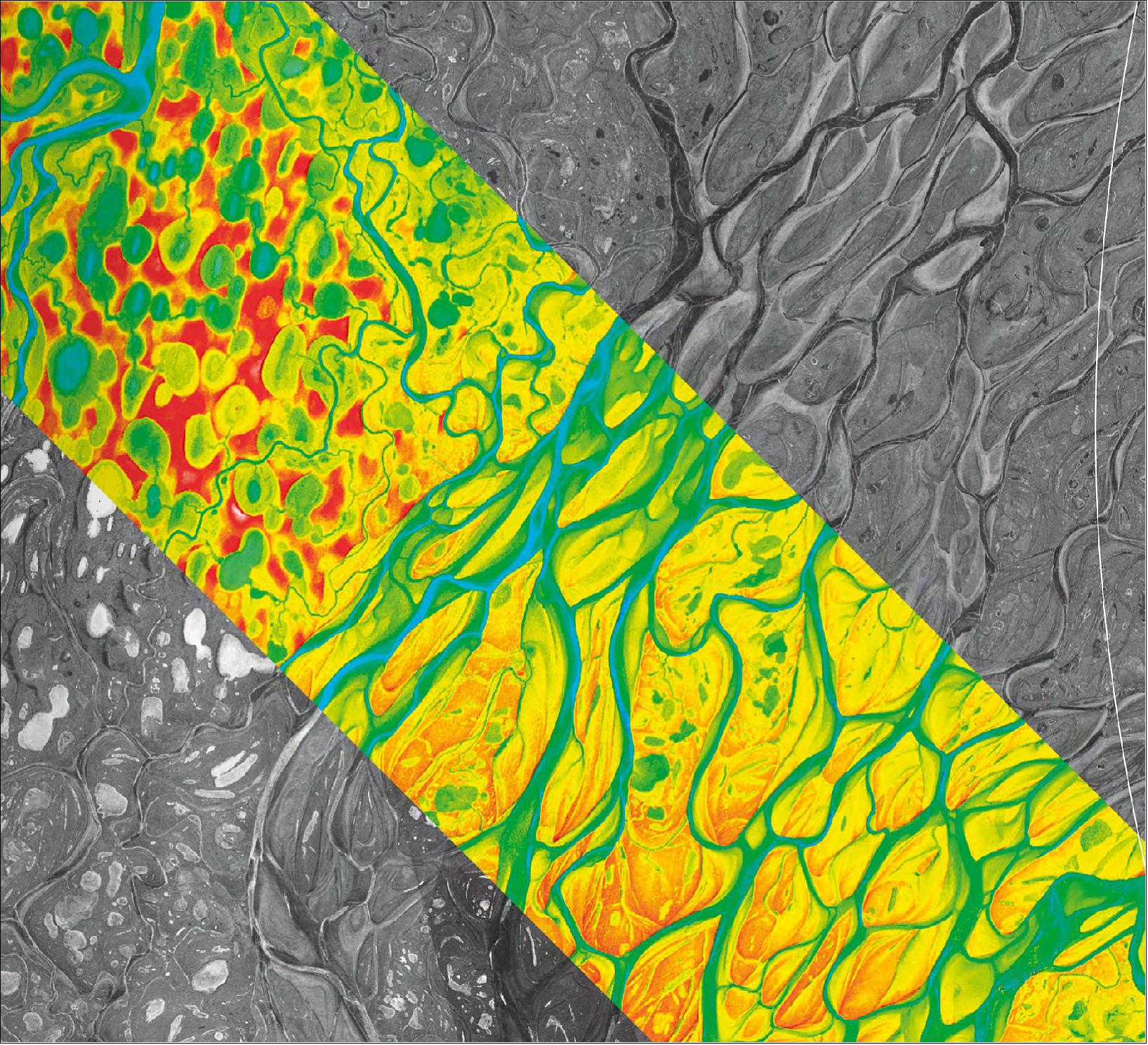
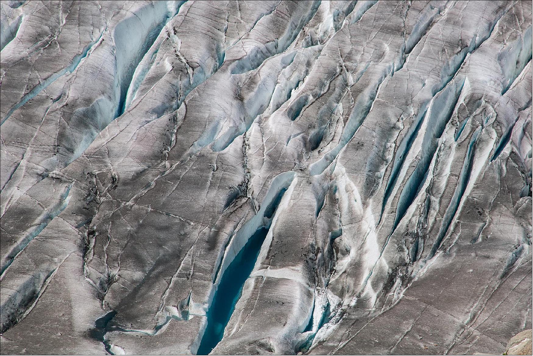
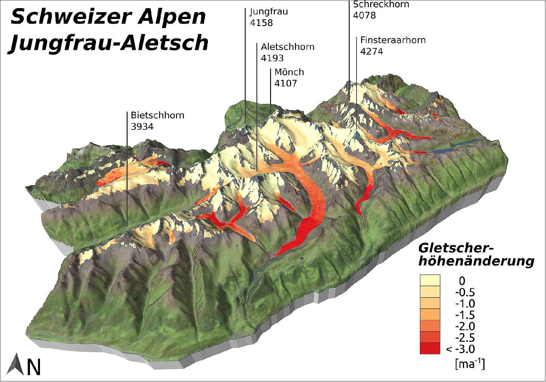
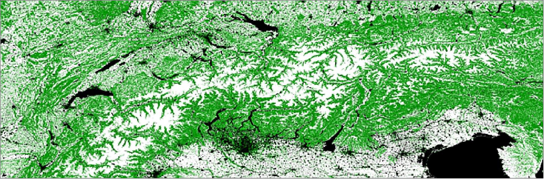
• July 8, 2020: A research team from Friedrich-Alexander-Universität Erlangen-Nürnberg (FAU) conducted a study analyzing changes in area and elevation for all Alpine glaciers from 2000 to 2014, revealing a 17% loss in total ice volume, equivalent to over 22 cubic kilometers. Using data from the TanDEM-X, SRTM, and Landsat missions, the study found that even higher glacier regions, particularly in the Central and Swiss Alps, are experiencing significant melting, with some areas like the Great Aletsch Glacier losing up to five meters in surface elevation annually. The study highlights the importance of accounting for dynamic changes in glaciated areas to avoid underestimating ice loss. 49)
• June 25, 2020: The TanDEM-X mission made a significant advancement in radar remote sensing, operating in tandem with its twin satellite TerraSAR-X to create a bistatic radar interferometer in space. This unique flight formation, with satellites sometimes only 120 meters apart, has enabled the creation of a highly accurate global Digital Elevation Models (DEM) of the Earth's entire landmass, achieving unprecedented precision with a height error of just 1.3 meters. Beyond the primary mission, TanDEM-X has facilitated detailed monitoring of dynamic Earth processes, such as glacial melt, deforestation, and urban development, with plans to extend its service for several more years. The mission's success has laid the groundwork for future projects like Tandem-L, which aims to map global biomass changes and enhance Earth observation capabilities through advanced bistatic L-band radar technology. 50)
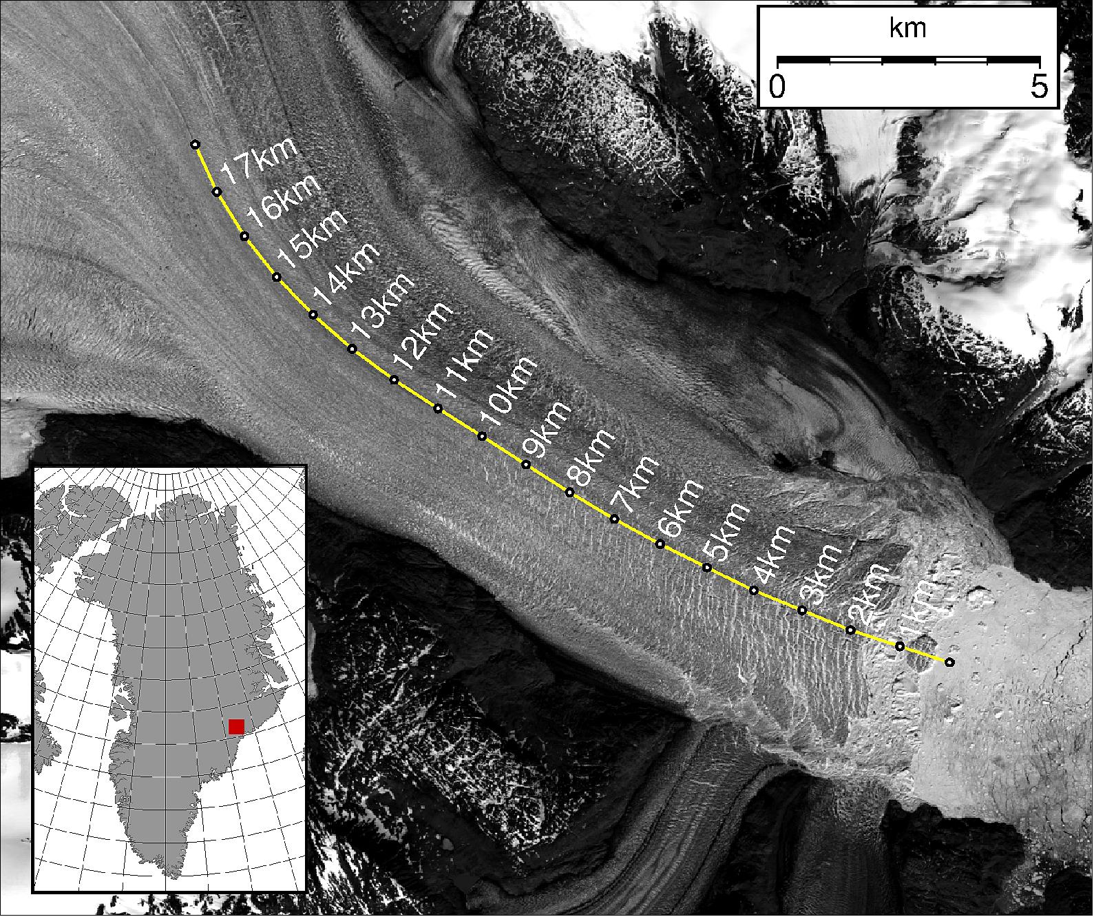
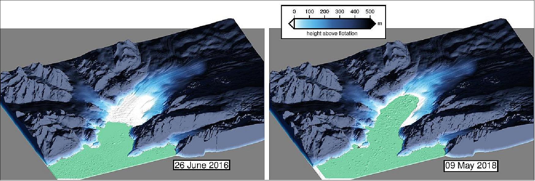
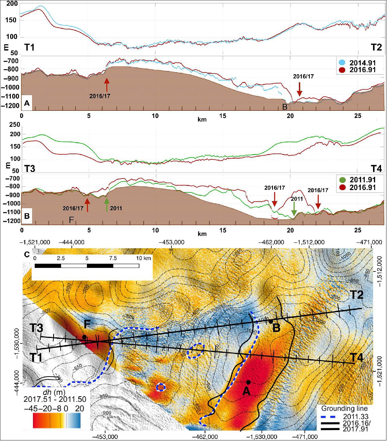
• September 13, 2019: The Kangerlussuaq Glacier, the largest glacier on Greenland's southeast coast, is rapidly retreating, losing about 24 km³ of ice annually, which represents roughly 5% of the Greenland ice sheet's total annual ice loss. This accelerated retreat is linked to the weakening of its protective ice melange due to atmospheric and oceanic warming, leading to significant ice loss even during winter. Between 2016 and 2018, the glacier's floating tongue retreated dramatically, and its thickness decreased by 35 meters. These findings, based on 150 TanDEM-X elevation models, highlight the glacier's vulnerability to climate change and the paramount role of advanced satellite monitoring in understanding these dynamics. 51)
• June 12, 2019: Accurate glacier mass measurements are very important in regions like South America's tropics, where glaciers provide essential dry-season drinking water. Traditional methods of measuring glacier mass, particularly in remote areas like the Patagonian Ice Fields, are challenging. However, a new analysis using TanDEM-X radar data has allowed scientists from Friedrich-Alexander-Universität Erlangen-Nürnberg to assess glacier mass changes across South America with unprecedented precision. Their study reveals that Patagonia's glaciers experienced significant mass loss, shrinking by 17.4 gigatons between 2000 and 2015, with some glaciers disappearing entirely. This research, published in "Nature Climate Change", underscores the potential of TanDEM-X and its successor, Tandem-L, for ongoing, detailed glacier monitoring. 52) 53)
![Figure 26: TerraSAR-X image of the Upsala Glacier in Patagonia, Argentina. Artificially colored TerraSAR-X image (strip mode) of the Upsala Glacier, created using data acquired on 7 January 2008. The colors provide information about the roughness of the terrain. Areas that appear predominantly smooth to the radar are tinted in darker shades of blue and gray. Areas with a coarser surface texture are shown in yellow [image credit: DLR (CC-BY 3.0)]](https://eoportal.org/ftp/satellite-missions/t/TanDEMX_250122/TanDEMX_Auto43.jpeg)
• August 2019: TanDEM-X has advanced spaceborne radar remote sensing by working in tandem with TerraSAR-X to create a single-pass SAR interferometer. This collaboration has resulted in the generation of global digital elevation models (DEMs) with a spatial resolution of 12 meters and vertical accuracy of 2 meters. In addition to its primary goal of producing a global DEM, TanDEM-X has supported the development and application of advanced SAR techniques, including multi-static SAR and polarimetric SAR interferometry. Despite exceeding their intended lifespan, both satellites continue to operate effectively. 54)
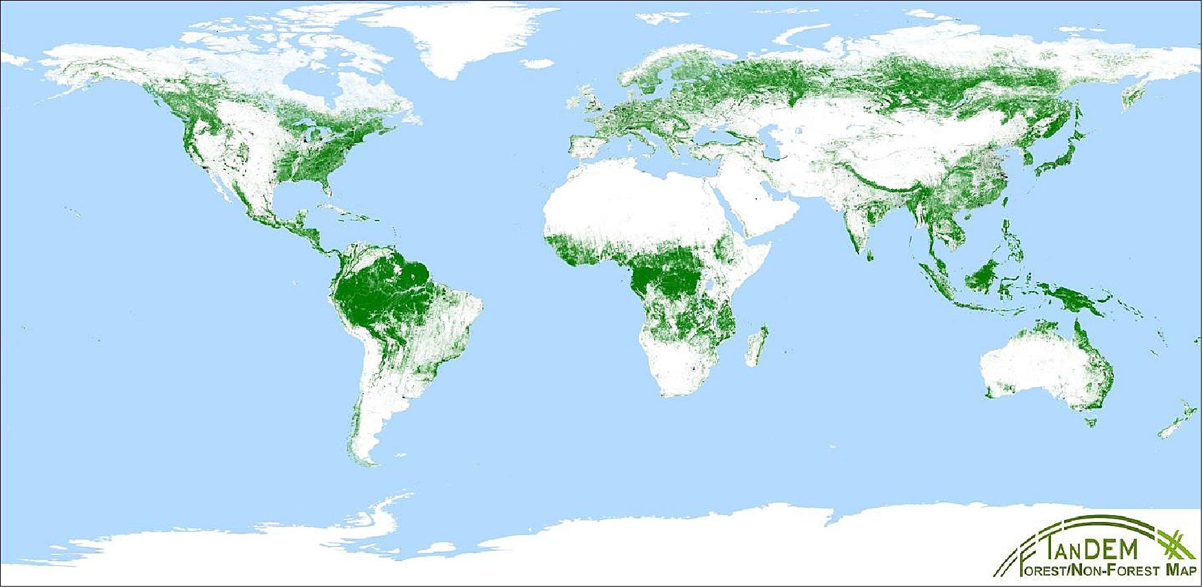
• May 06, 2019: Forests, crucial for regulating greenhouse gases and supporting biodiversity, are being rapidly depleted. To address this, the German Aerospace Center (DLR) has developed the global TanDEM-X Forest/Non-Forest Map using radar data from the TanDEM-X mission and advanced AI algorithms. This map, with a 50-meter resolution, provides comprehensive coverage of forested areas, including tropical regions often obscured by clouds. It supports precise biomass estimation, crucial for understanding the global carbon cycle and aiding in environmental protection and land-use planning. Validated with additional remote sensing data, this map is available for free to scientists and contributes to future missions like Tandem-L, which aims to enhance forest monitoring and address global environmental challenges. 55)
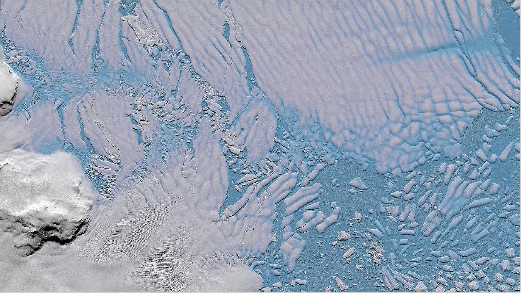
• February 1, 2019: The Thwaites Glacier in western Antarctica, a critical contributor to global sea level rise, is melting rapidly, with a 350-meter cavity revealing accelerated ice loss. Utilizing high-resolution, three-dimensional elevation models from German radar satellites TerraSAR-X and TanDEM-X, scientists have precisely measured these changes, uncovering that 14 billion tons of ice have melted in recent years. These observations, supported by additional satellite data, have provided new insights into the glacier's dynamics, particularly the interactions between ice and penetrating seawater. This study, published in Science Advances, underscores the importance of advanced radar satellite technologies in improving climate predictions and understanding the impact of glacier melt on sea levels. 56) 57)
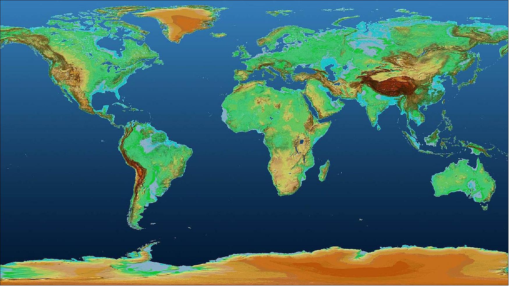
• October 8, 2018: The German Aerospace Center (DLR) has released the 90-meter resolution TanDEM-X Digital Elevation Model (DEM) for free scientific use, offering a highly accurate, global 3D map of Earth's land surfaces. Generated by the TanDEM-X and TerraSAR-X radar satellites, this dataset covers over 148 million km² with a 1-meter absolute height accuracy. While higher resolution models remain restricted, the 90-meter DEM is expected to see widespread use in Earth sciences, environmental studies, and infrastructure planning. Both satellites, despite surpassing their expected lifetimes, continue to function well, enabling ongoing observation of topographic changes worldwide. 58)
• June 2018: The TerraSAR-X (TSX) and TanDEM-X (TDX) missions use a shared ground segment. Initially designed for TSX, this segment was expanded to include TDX, with both satellites contributing to the global Digital Elevation Model (DEM) production and serving individual scientific and commercial requests. Despite surpassing their nominal lifetimes in 2012 and 2015, TSX and TDX continue to operate effectively, with sufficient propellant and battery capacity to extend the mission for several more years. The satellites' radar instruments remain highly stable and accurately calibrated, ensuring the ongoing production of high-quality SAR data.
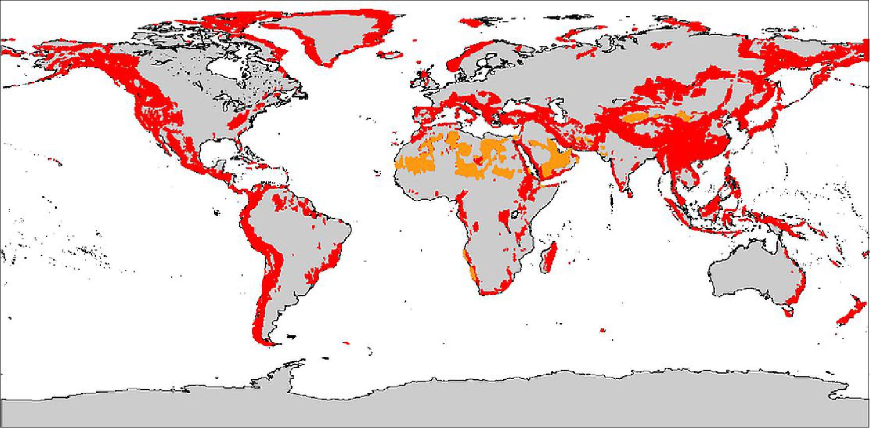
The mission has successfully completed the global TanDEM-X DEM, consisting of more than 19,000 tiles, with an outstanding cumulative absolute height error of 0.9 meters. Recognizing the Earth's dynamic surface changes, a new "Change DEM" product was initiated in 2017 to monitor topographic changes globally. This product involves acquiring additional data from September 2017 to the end of 2019, with a focus on areas such as glaciers, forests, deserts, and permafrost regions (as outlined in Figure 24). The Change DEM will use the original TanDEM-X DEM as a starting point, applying advanced processing techniques to ensure high accuracy, with the primary goal of detecting temporal changes in Earth's topography while maintaining low random height error across different terrains. The mission is set to continue beyond 2020, leveraging the remaining resources to update and enhance the global DEM and produce the Change DEM as a standalone product. 59)
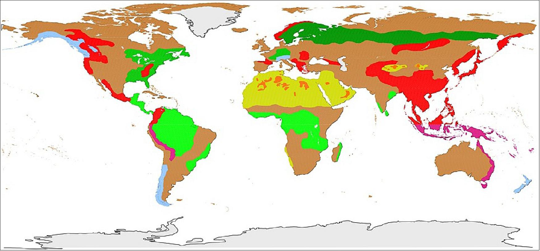
• February 9, 2018: The TerraSAR-X and TanDEM-X satellites continue their mission in close formation, focusing on scientific observations and capturing topographic changes. A key project under this mission is the TanDEM-X Forest/Non-Forest Map, developed by DLR's Microwaves and Radar Institute. This project aims to create a global forest classification using interferometric radar data collected between 2011 and 2015. The classification relies on the volume correlation factor, derived from interferometric coherence, to identify vegetated areas. A fuzzy multi-clustering classification approach is applied to the data, which uses various observables, such as calibrated amplitude and bistatic coherence, to accurately distinguish between forest and non-forest regions. 60) 61) 62)
• July 2017: Following the launch of TanDEM-X in 2010, global DEM acquisitions began, with over 500,000 Raw DEMs generated using multibaseline interferometric techniques. The first and second global coverages were completed by 2013, with challenging areas like Antarctica and deserts re-acquired under specific conditions to ensure accuracy. By September 2016, the global DEM was completed, boasting a remarkably low absolute height error of 0.9 m for non-forested and non-ice-covered areas. The mission's success in achieving high data quality and coverage led to an extension agreement between DLR and Airbus Defence & Space to continue the mission. This new phase will focus on improving the global DEM, generating a global change layer, and exploring applications for future SAR missions like Tandem-L. 63) 65)
• July 6, 2017: Airbus DS has launched WorldDEM4Ortho, an advanced global elevation model designed for the precise orthorectification of high-resolution optical and radar satellite data. This model corrects distortions caused by topographical variations and satellite orientation, making satellite images suitable for GIS and mapping applications. WorldDEM4Ortho is derived from the WorldDEM dataset, which was generated using data from the TanDEM-X and TerraSAR-X satellites, offering a vertical accuracy of four meters in a 24-meter raster. It also features automated processes to remove terrain artifacts, flatten water bodies, and smooth landscapes, ensuring consistent and accurate global coverage for the growing demand in geolocated applications. 66)
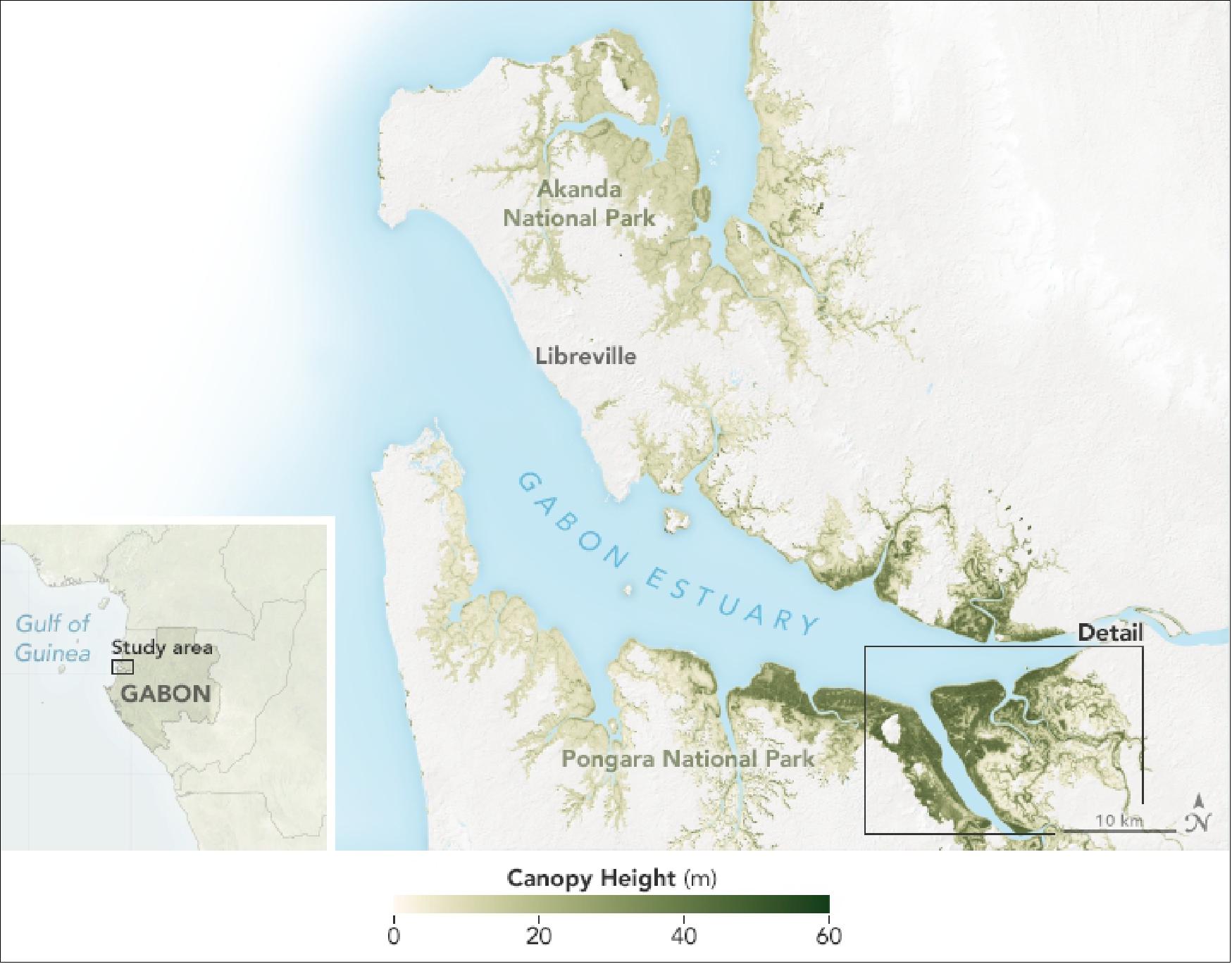
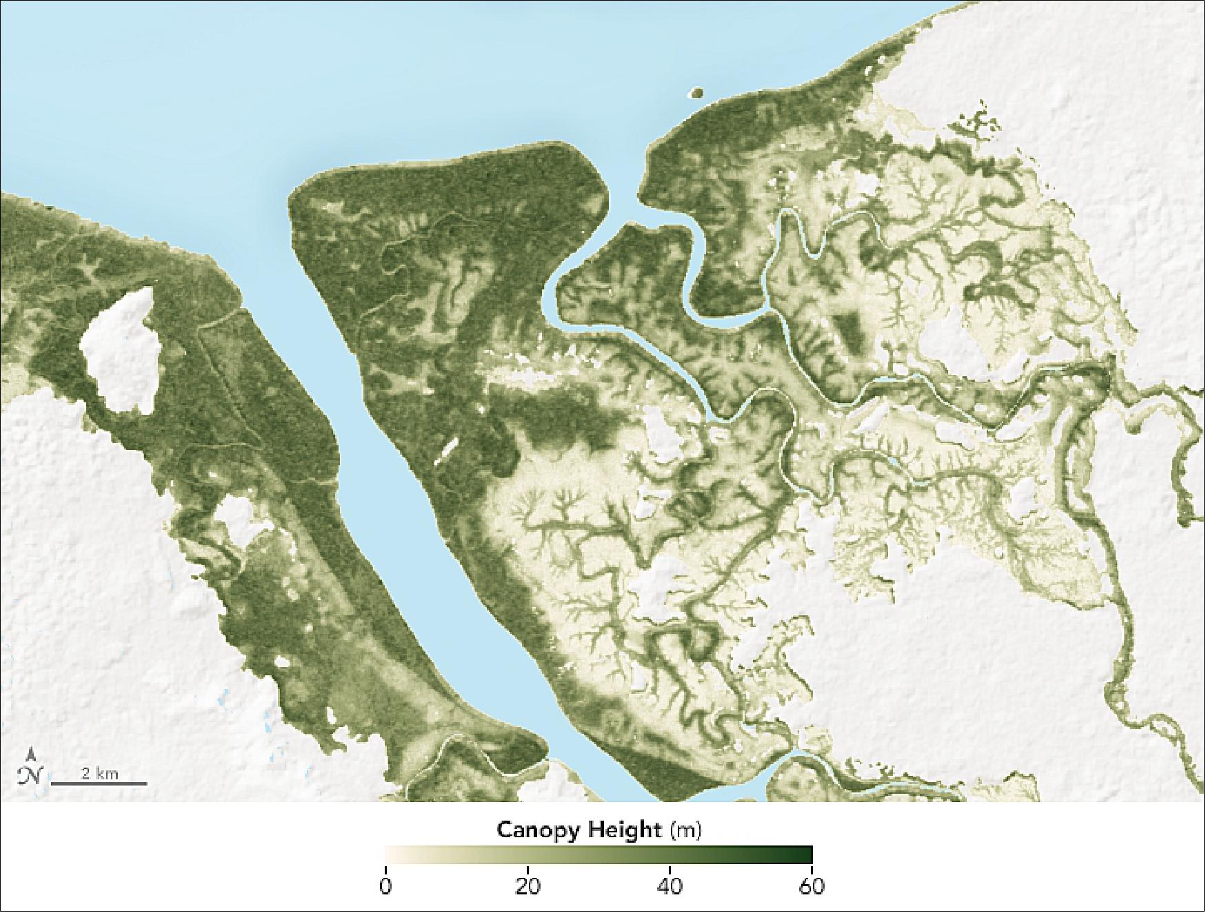
• May 19, 2017: Mangroves, though only comprising 3% of global forest cover, are the most carbon-rich tropical forests, making their preservation crucial for climate regulation. The loss of mangroves can contribute significantly to global carbon emissions from deforestation. Recent research, including satellite radar data from Tandem-X, has mapped mangrove canopy heights in Gabon's Akanda and Pongara national parks, revealing some of the tallest mangroves in the world. These height maps, showcased in Figures 28 and 29, are essential for estimating biomass and carbon storage, which vary across different mangrove species and structures, highlighting the importance of both air- and ground-based data in understanding global carbon stocks in these ecosystems. 67) 68) 69) 70)
• January 13, 2017: TerraSAR-X and TanDEM-X, two satellites in close formation, continue to perform bistatic observations for scientific purposes, with both satellites managing their resources efficiently. Each has used about half of its hydrazine, their batteries remain in good condition, and radar imagery quality has been consistently up to standards. 71)
• October 17, 2016: The German satellite duo TerraSAR-X and TanDEM-X have consistently delivered one-of-a-kind Earth observation data since 2007 and 2010, hence shaping the international research landscape. Now, scientific users from across the globe have gathered for the TerraSAR-X and TanDEM-X Science Meeting at DLR (German Aerospace Center) in Oberpfaffenhofen, where they will discuss the results obtained from the data and define requirements for future remote sensing technology. 72)
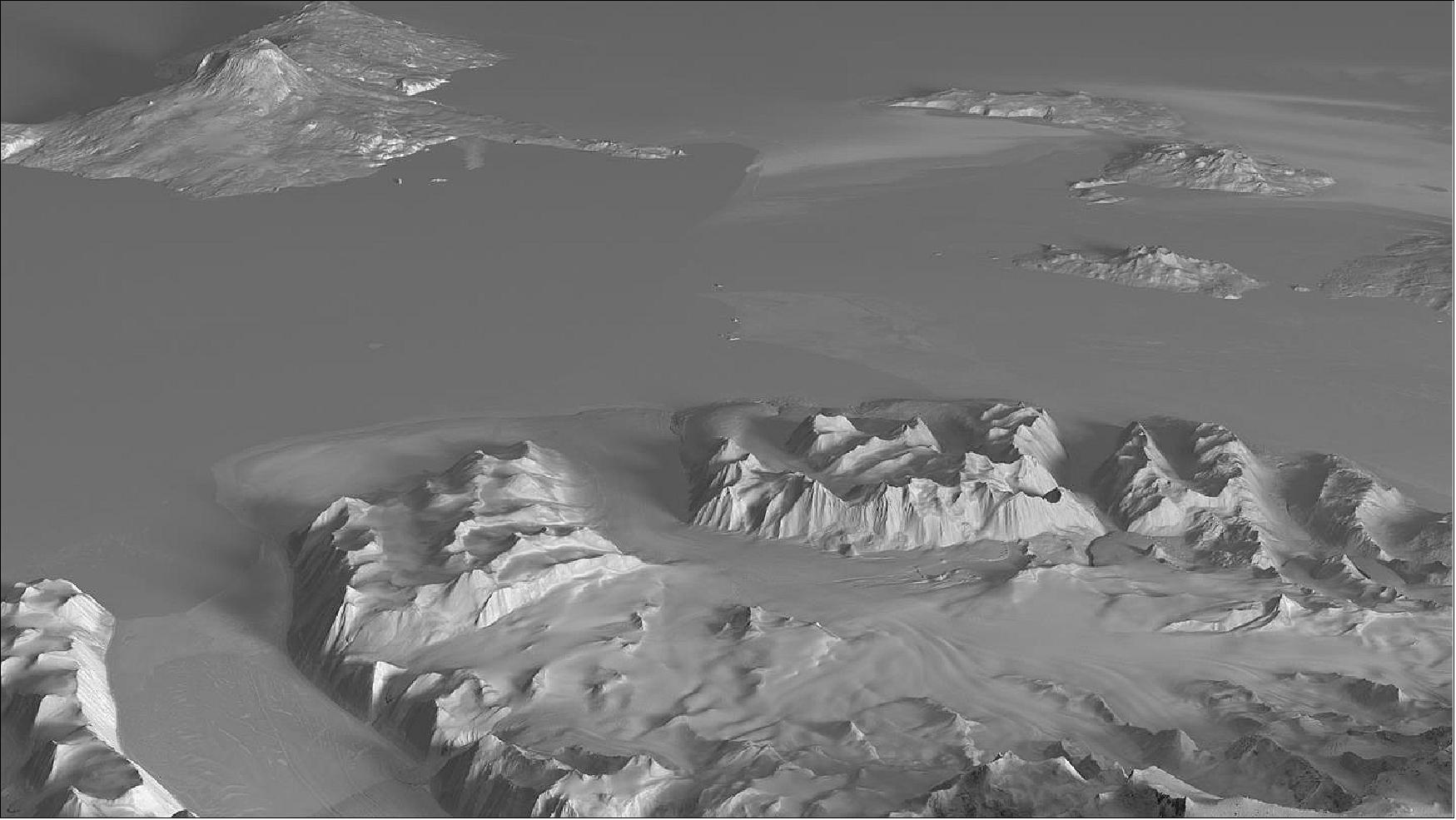
Legend to Figure 30: Within the framework of the German TSX/TDX radar mission, the polar regions were surveyed for the first time in a comprehensive and highly accurate manner, which is of vital interest to climate research. The terrain model of Figure 30 shows a region of the Antacrtic around the 3794 m Mount Erebus (upper left), an active volcano covered by glacier ice.
• October 4, 2016: The TanDEM-X satellite mission has successfully completed a highly accurate three-dimensional map of Earth's land surface, covering approximately 150 million km² with an unprecedented elevation accuracy of just one meter. This achievement is the result of its system calibration and the close formation flight of TerraSAR-X and TanDEM-X. The satellites are laying the groundwork for future missions like Tandem-L to monitor Earth's dynamic topography. 73)
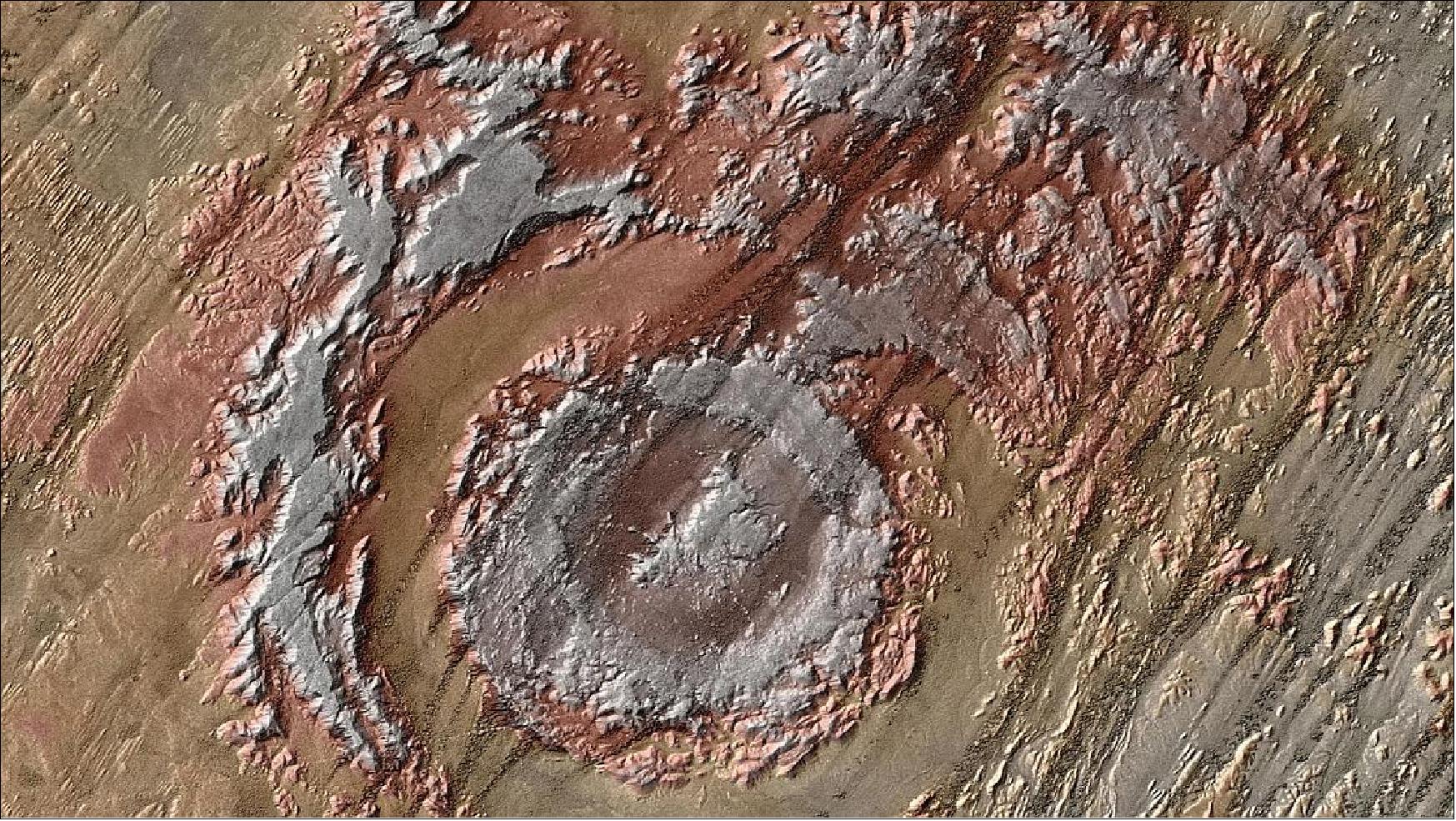
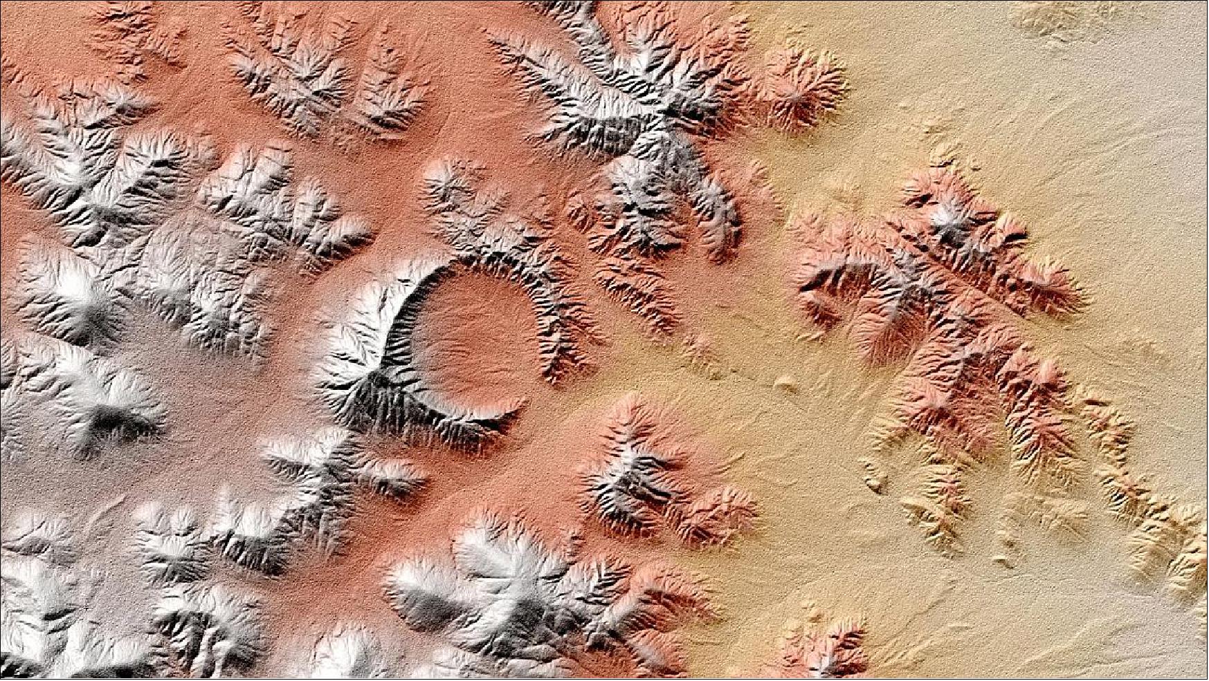
Legend to Figure 31: The 'Nevada Test Site' was, from 1951, the area for numerous nuclear tests. The desert area, 100 km northwest of Las Vegas, is dotted with explosion craters.
• July 2016: The TSX and TDX satellites were designed for a nominal lifetime of 5.5 years. Predictions based on the current status of system resources indicate a lifetime for both satellites past 2020. 74)
• June 2016: Building on the success of the TanDEM-X mission in creating a global Digital Elevation Model (DEM) with exceptional accuracy, the mission is now advancing towards producing High-resolution DEMs (HDEMs) for specific areas. These HDEMs aim to provide even greater detail, with a resolution of less than 6 meters and a targeted relative height error of 0.8 meters, compared to the 2 meters achieved in the standard DEM. The regions of interest for these HDEMs include flat, non-forested areas with good coherence, and additional focus areas will be covered multiple times to enhance accuracy. 75) 76)
Technically, the production of HDEMs involves several key improvements. The radar acquisition bandwidth has been increased to 150 MHz, compared to 100 MHz used in the original DEM, to ensure sufficient multi-looking with the higher resolution. Block Adaptive Quantization (BAQ) has been upgraded from 3 bits/sample to 4 bits/sample where possible, further improving height accuracy. Additionally, the satellite formation has been optimized, with the horizontal distance between the satellites increasing from 600 meters to 1200 meters over time, while maintaining a consistent vertical distance. These technical enhancements aim to meet the stringent accuracy requirements and demonstrate the high potential of the HDEM production process.
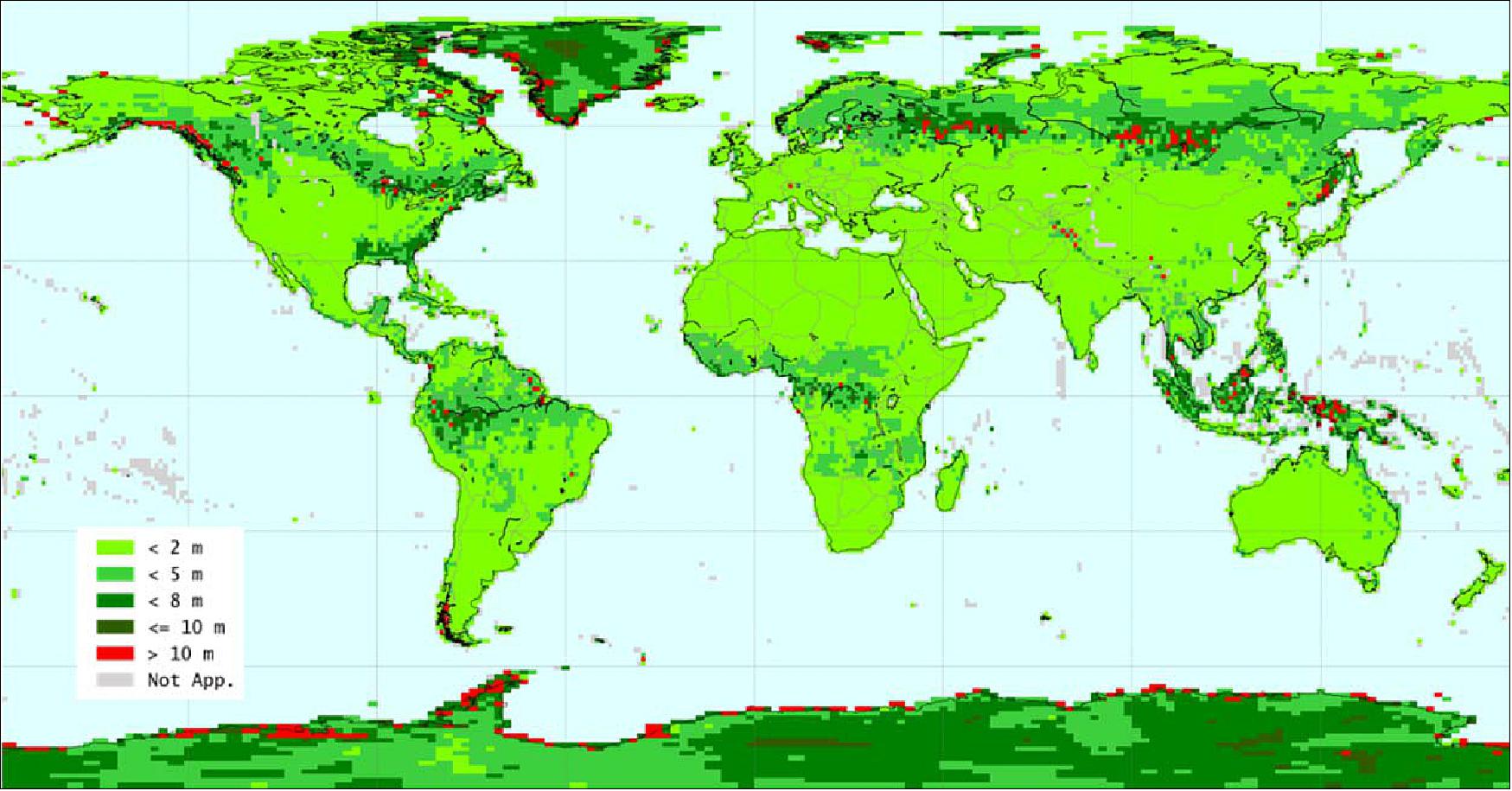
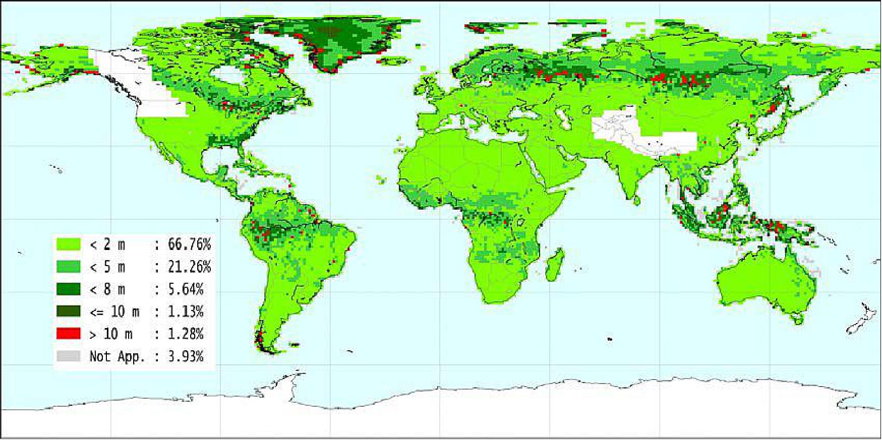
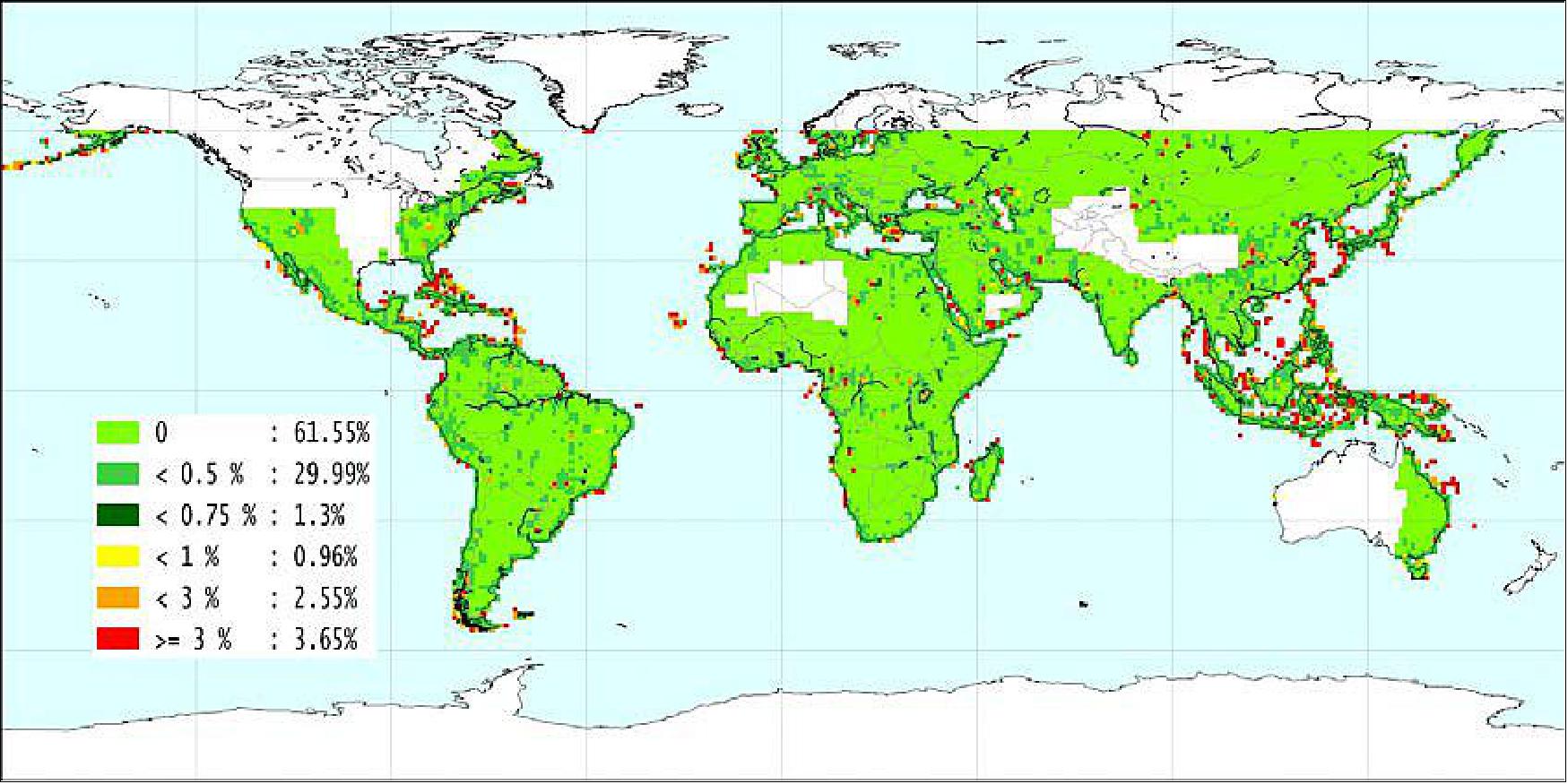
• June 2016: Digital Elevation Models (DEMs) are essential for various scientific and commercial applications, with the TanDEM-X mission enhancing global elevation data significantly. The mission, initiated in December 2010, aimed to produce a high-resolution, consistent, and up-to-date global DEM. As of February 2016, over 15,000 of the approximately 20,000 planned geocells have been made available. The TanDEM-X global DEM meets and surpasses the specifications outlined in Table 4, which sets a spatial resolution of 0.4 arcseconds (12 meters at the equator) and specifies data coverage requirements. The absolute height accuracy of the DEM is 1.318 meters, exceeding the 10-meter accuracy requirement specified in Table 5. Only 194 geocells (1.2%) have an absolute height accuracy greater than 10 meters, while the majority, 67%, achieve an accuracy of less than 2 meters. 77) 78)
Parameter | Accuracy | Requirement |
Absolute height accuracy | 90% linear error – globally | ≤ 10 meter |
Relative height accuracy | 90% linear point-to-point error in 1º x 1 º geocell | ≤ 2 meters (slope ≤ 20%) |
Data coverage | 97% of all global land mass | |
Number of DEM geocells | 15,154 |
Accumulated Number of Validation Points | 12,490,957 |
Mean Height Deviation of Validation Points (m) | 0.046 |
Accumulated Absolute Height Accuracy of 10 m (linear error) | 99.66% |
Accumulated Absolute Height Accuracy with 90% linear error (m) | 1.318 |
In terms of relative height accuracy, 14,008 geocells meet the required 90% confidence levels of 2 meters for flat terrain and 4 meters for steep terrain. As shown in Figure 33, up to 1.32% of geocells fall short of these specifications due to factors like dense forestation or small land areas. Data coverage, detailed in Figure 34, indicates that voids over land amount to just 0.0766% of the data, reflecting a coverage accuracy of over 99.9%. While some geocells, particularly those in islands or desert regions, have higher void percentages, their contribution to the overall data quality is minimal. The calibration process also accounts for variations in radar and laser-based height measurements, especially in Greenland, where the radar system penetrates deeper into ice compared to the ICESat laser system.
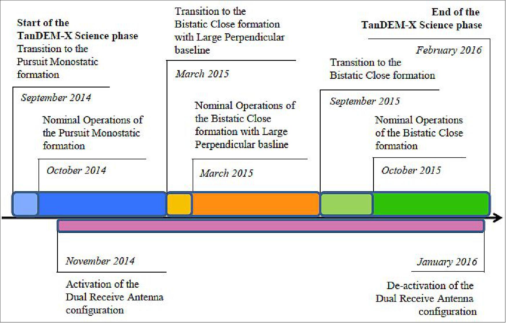
• May 2016: The TerraSAR-X and TanDEM-X satellites have been operational since January 2008 and January 2011, respectively. The TanDEM-X science phase, beginning in September 2014, involved significant adjustments to long-standing operational concepts and ground software upgrades. This phase required extensive validation campaigns to ensure compliance with mission requirements, particularly for payload data downlink and constellation transitions. The operations team managed these challenges effectively, with careful planning and adaptation to evolving formation geometries and mission needs. The science phase proceeded without major issues, successfully meeting the objectives and maintaining smooth satellite operations.
During the TanDEM-X science phase, the mission employed three distinct formation geometries and introduced the Dual Receive Antenna configuration. From September 2014 to March 2015, the satellites used a Pursuit Monostatic Far formation, focusing on sea ice and glacier measurements. The introduction of quad-polarization acquisitions in November 2014 enabled detailed monitoring of ground moving targets and vegetation. In March 2015, the formation shifted to Bistatic Close with a Large Perpendicular Baseline for high-resolution DEMs and vegetation monitoring. The phase concluded in February 2016 with a pure Bistatic Close formation, supporting research on forests and ocean currents, as illustrated in Figure 35. 79) 80)
• November 24, 2015: Airbus Defence and Space and the German Ministry of Defence have signed a contract for the use of TanDEM-X mission data to update the Bundeswehr's Digital Elevation Model (DEM). The agreement provides licenses for the global elevation dataset covering 150 million km² of land and includes support services for data management, editing, and dissemination. It also offers additional support and training to ensure users can effectively utilize the data. The 3D data from the TanDEM-X mission enhances visualization for military purposes, including surveillance, reconnaissance, mission planning, and operational tasks such as obstacle mapping and flight path planning. 81)
• October 2015: In 2016, the TerraSAR-X and TanDEM-X satellites will continue their operations in a close bistatic formation with nominal parameters. The TanDEM-X mission aims to complete its global Digital Elevation Model (DEM) by autumn 2016 and will also pursue further science and high-resolution DEM (HDEM) acquisitions. An agreement between DLR and Airbus Defence and Space ensures mission continuity beyond 2016, with predictions indicating that both satellites could operate until 2020 based on available onboard resources. 82)
• September 2015: The WorldDEM database is expanding with more regions becoming fully available, including Europe, Australia, and Africa. This global elevation model provides critical terrain information for evaluating exploration sites, supporting seismic planning, and conducting geophysical surveys. Particularly valuable for Africa, which is rich in mineral reserves and has significant oil and gas production, WorldDEM offers reliable and seamless high-quality data even for remote and challenging locations, aiding geological prospecting and feasibility studies. 83)
• June 12, 2015: Digital Elevation Models (DEMs) of the Earth's impact craters, created using data from the TerraSAR-X and TanDEM-X radar satellites, offer unprecedented precision in mapping these features. With only 188 known craters worldwide, ranging from 10 meters to 160 kilometers in diameter, DLR's 3D DEMs, achieved with vertical precision better than 2 meters, allow detailed analysis of these geological formations. The DEMs, which cover 65% of Earth's landmass, provide insights into crater size, preservation state, and features obscured by vegetation. The use of radar technology ensures accurate mapping regardless of weather conditions, enhancing our understanding of these ancient impacts. 84)
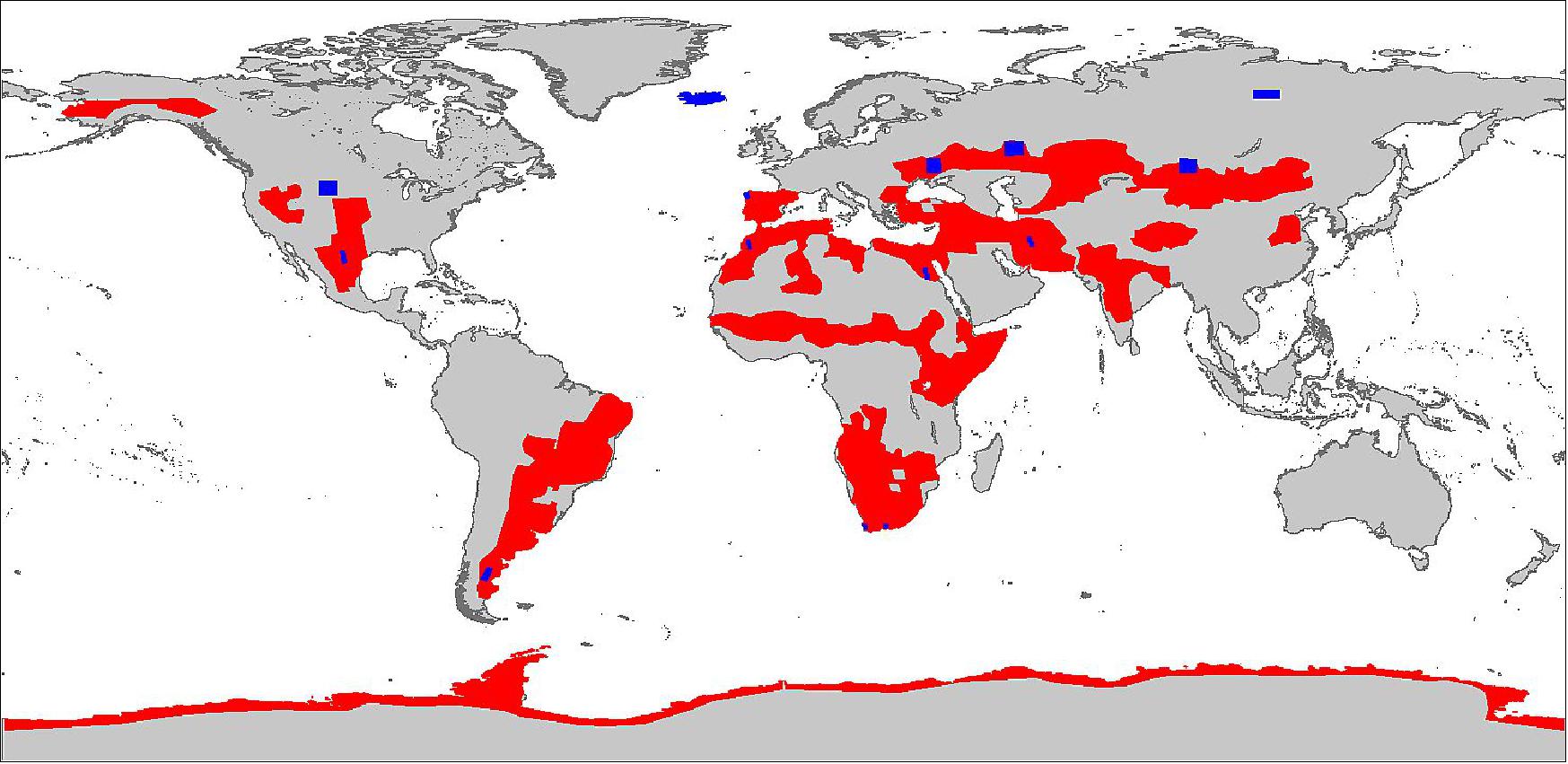
• May 2015: The TanDEM-X mission aims to produce a highly accurate global Digital Elevation Model (DEM) using interferometric Synthetic Aperture Radar (SAR) data from its two satellites. The mission's target is to achieve horizontal and vertical accuracies of less than 10 meters at a 90% confidence level, with relative vertical accuracy specifications of 2 meters for flat terrain and 4 meters for steep terrain within 1º by 1º cells. This involves processing over 500,000 individual SAR scenes into a global DEM. Systematic acquisition has been performed, including multiple passes over challenging terrains like mountains and deserts, to address issues such as phase unwrapping and varying data quality. Interferometric quality and calibration have been continuously monitored, with the results summarized in Table 6, showing that 87% of scenes meet the ±10 meters accuracy specification. The calibration process has significantly improved height accuracy, as detailed in Figure 40, which illustrates baseline estimation errors. 85)
As of February 2015, the TanDEM-X mission had processed over 458,000 scenes, with a mean coherence value greater than 0.6 for 89% of the scenes, indicating reliable interferometric performance. The systematic acquisition phase was completed in August 2014, and data from nearly 8856 final DEM tiles have been analyzed, showing that the data quality is within the specified accuracy range. The final global DEM, expected to be completed in the second half of 2016, will integrate approximately 20,000 tiles, with ongoing quality monitoring ensuring the final product exceeds accuracy requirements. The relative height accuracy predicted from quicklook products aligns well with the final DEM data, confirming the mission's success in achieving high precision and reliability.
| Mean coherence >0.6 | Relative height error confidence | Mean height offset < 10 m | |
1st Global Coverage | 84.1% | 88.0% (flat) | 91.1% (steep) | 93.6% |
2nd Global Coverage | 86.6% | 90.0% (flat) | 89.9% (steep) | 92.0% |
Additional coverage | 88.5% | 68.6% (flat) | 82.9% (steep) | 85.2% |
Desert acquisitions | 96.4% | 90.8% (flat) | 89.8% (steep) | 89.2% |
Difficult terrain | 93.3% | 81.6% (flat) | 92.3% (steep) | 74.0% |
Combined quality | 89.3% | 96.8% (flat) | 98.8% (steep) | 87.6% |
• April 2015: The WorldDEM Digital Terrain Model (DTM) is now commercially available, offering a detailed representation of the Earth's bare terrain by removing vegetation and man-made structures from the WorldDEM™ Digital Surface Model (DSM). This high-quality model supports various applications including civil engineering, natural resource management, and military operations by providing a precise foundation layer for tasks such as road design and terrain analysis. The WorldDEM DTM is derived from data acquired by the TerraSAR-X and TanDEM-X satellites, operated in collaboration with DLR. Three product levels are available: WorldDEMcore, which includes unedited processing output; WorldDEM™, which ensures a void-free and hydrologically consistent terrain description; and WorldDEM DTM, which focuses on bare Earth elevation. These models are valuable for global-scale geospatial applications, from topographic mapping to defense and security.86) 87) 88) 89)
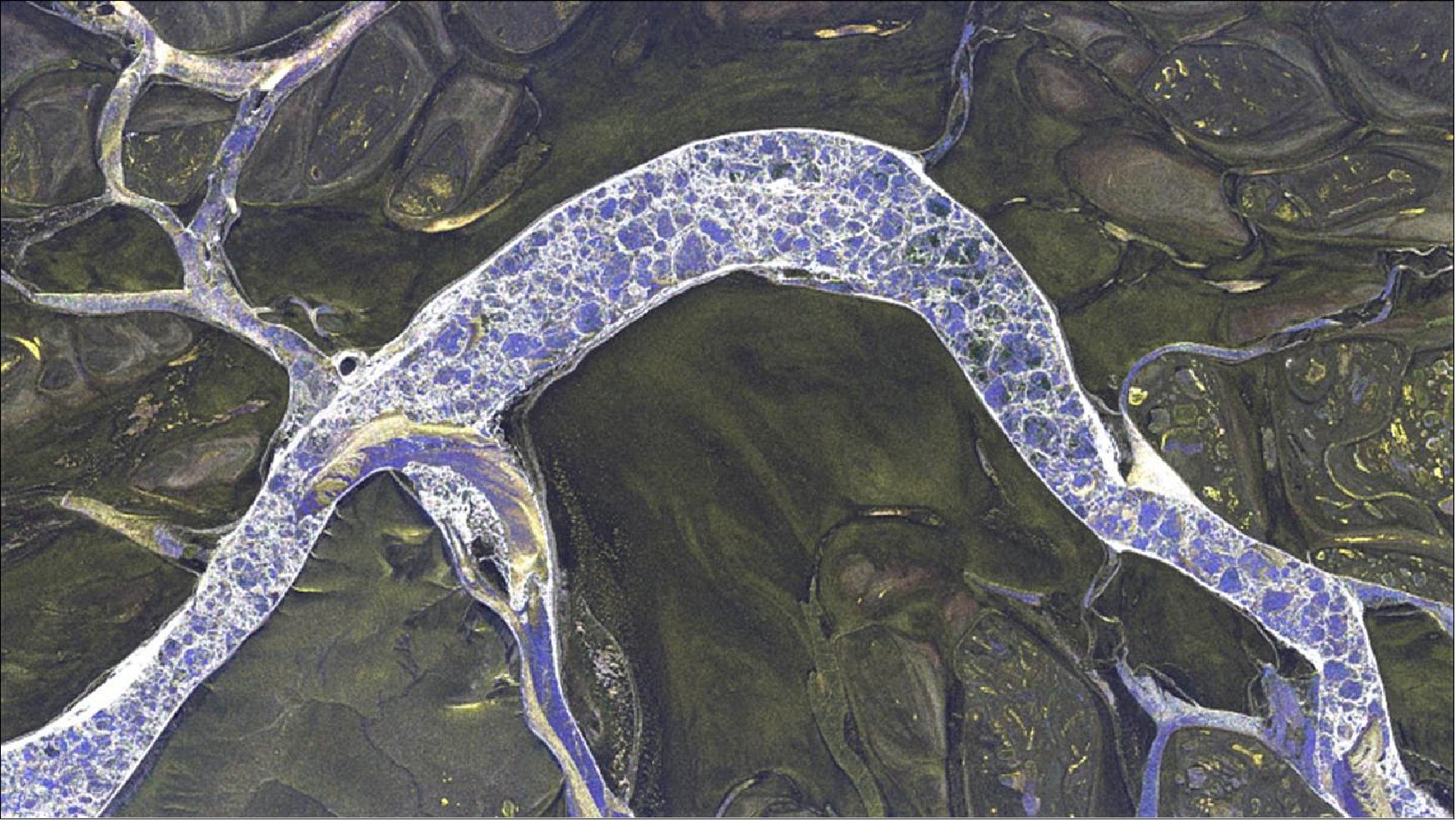
• April 1, 2015: The TanDEM-X mission has provided crucial insights into the Earth's cryosphere, particularly in high-latitude permafrost zones like the Lena Delta in Siberia. By analyzing radar images from TanDEM-X, researchers can assess the conditions of ice-covered bodies of water and track changes in permafrost due to climate warming. This data is vital for understanding the stability of permafrost, its impact on ecosystems, and potential greenhouse gas releases. The mission's success is paving the way for the Tandem-L project, which aims to achieve a hundredfold increase in imaging capability, enabling more frequent and detailed monitoring of dynamic changes across the Earth's surface. This advancement could significantly enhance our understanding of the biosphere, geosphere, cryosphere, and hydrosphere. 90)
• February 2015: The TanDEM-X and TerraSAR-X missions are operating effectively, with a new science phase running from September 2014 to December 2015. This phase includes the "Pursuit Monostatic Phase," where TanDEM-X flies 76 km behind TerraSAR-X, both acquiring monostatic data for interferometric processing. From March 2015, the mission transitions to the "Bistatic Phase," initially featuring large horizontal baselines up to 3600 m, and later shifting to a smaller baseline of approximately 250 m. Concurrently, TerraSAR-X continues to generate 2D SAR observations in various operational modes. The primary goal of the TanDEM-X mission is to produce a global Digital Elevation Model (DEM), with additional support provided to the ongoing science mission. 91)
• October 10, 2014: After four years of successful data acquisition, the TanDEM-X mission has entered its Science Phase, which began in September 2014 and aims to optimize radar techniques and test innovative applications. The mission, involving the TerraSAR-X and TanDEM-X satellites in close formation, seeks to generate a highly accurate global topographical map of Earth. The current phase includes the "Pursuit Monostatic Mode," allowing for high-resolution elevation data, crucial for studying climate change impacts such as permafrost thawing. By late 2015, a comprehensive 3D elevation model is expected to be completed, with over 2500 TB of data already acquired. Looking ahead, DLR is planning the Tandem-L mission to achieve even higher imaging capabilities and more frequent global observations, potentially launching in 2020. 92) 93)
• June 2014: Since TanDEM-X's launch in June 2010, the mission has achieved stable operations in close formation, with global Digital Elevation Model (DEM) acquisitions beginning in December 2010. By March 2013, the first two global coverages were completed, excluding Antarctica, which was later mapped during winter for improved signal-to-noise ratio. Following a reconfiguration of the Helix formation in April 2014, and additional gap-filling efforts, final data acquisitions are expected to conclude in the second half of 2014. Over 350,000 Raw DEMs have been produced, with final calibration and mosaicking processes operational since 2013. While the quality of the initial final DEMs is within specifications, comprehensive global DEM completion is anticipated by the end of 2015. TanDEM-X's success paves the way for future missions like Tandem-L, which aims to offer even higher accuracy for monitoring dynamic Earth processes. 94) 95)
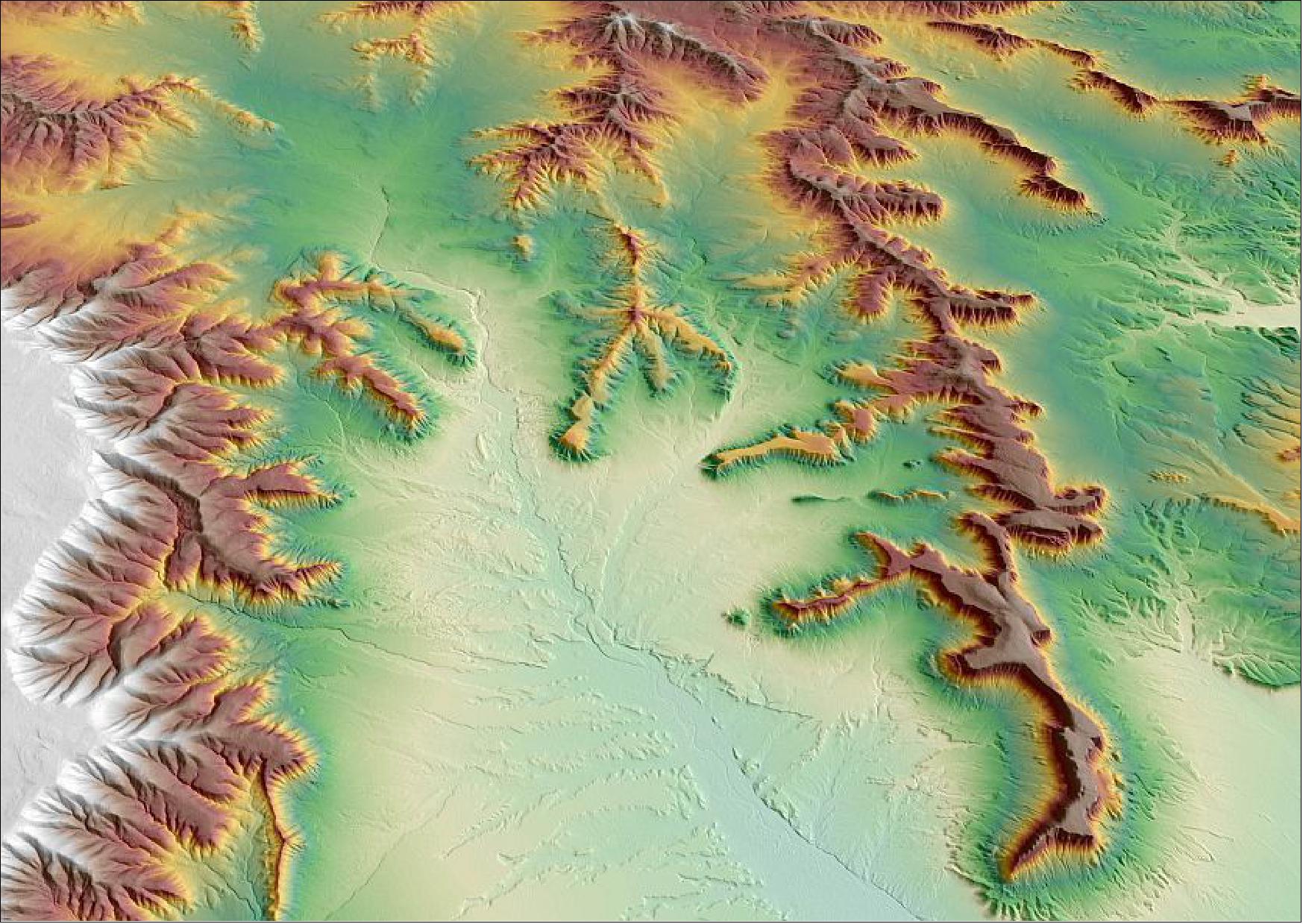
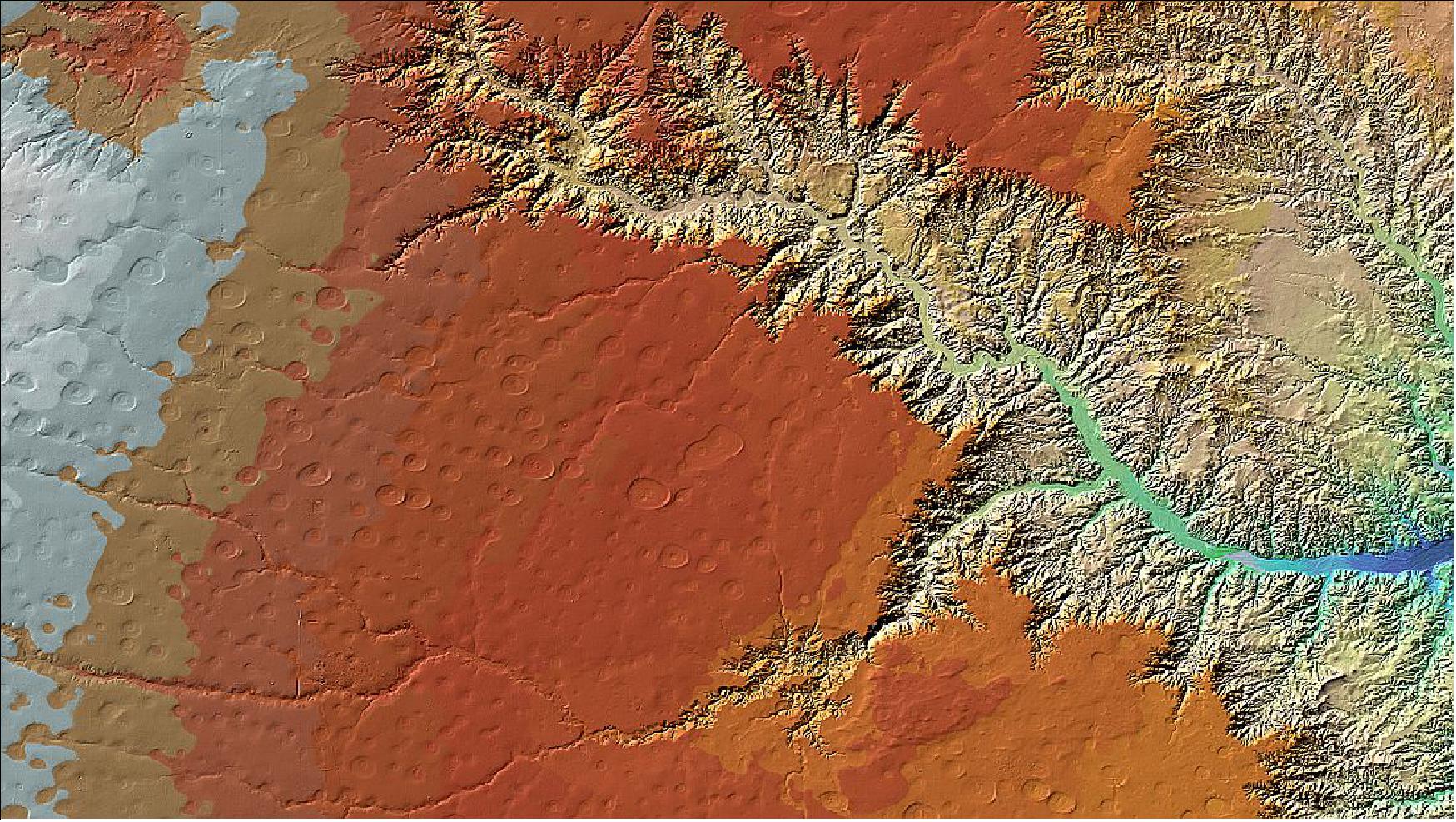
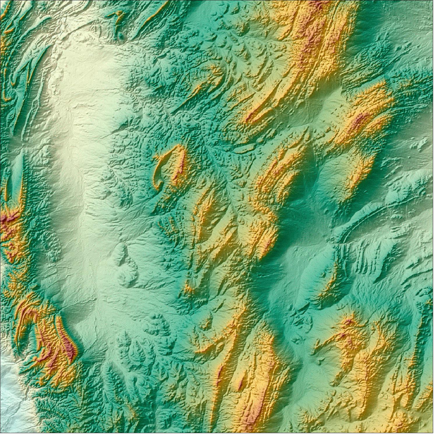
• May 19, 2014: DLR is making the first elevation models of a new global topography for scientific use. Canyons in Australia's Flinders Ranges National Park, Canadian islands and the rugged volcanic landscape of Russia's Kamchatka Peninsula are revealed at a level of detail 30 times greater than anything seen to date. Over 800 scientists from 31 countries have already registered to work with these highly accurate elevation models. The complete and uniform terrain model is scheduled for completion by the end of 2015. Two sample DEMs are shown in Figures 44 and 45. 96)
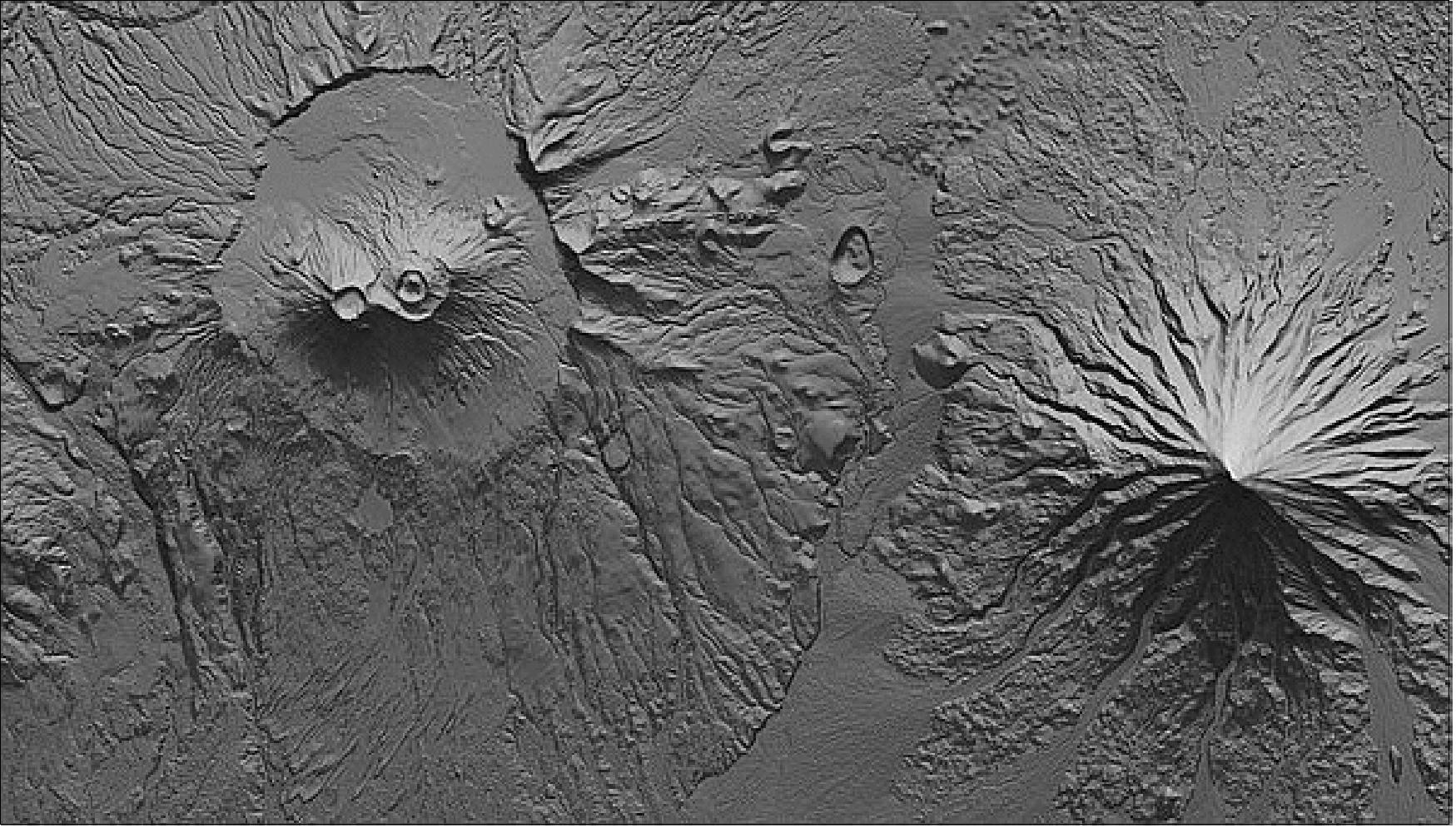
Legend to Figure 44: A detailed view around the Krasheninnikov Caldera and Kronotsky Volcano is presented as a shaded relief map. Maps of this kind using TanDEM-X data permit analyses of possible lava flow, used to determine endangered areas.
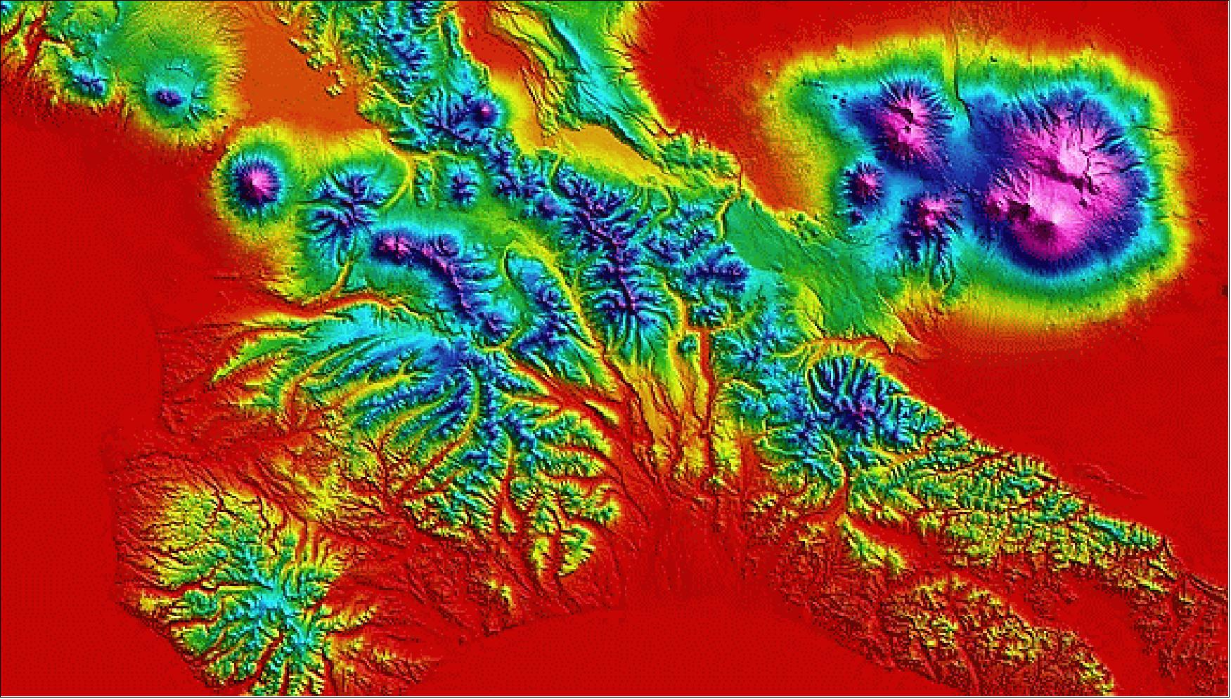
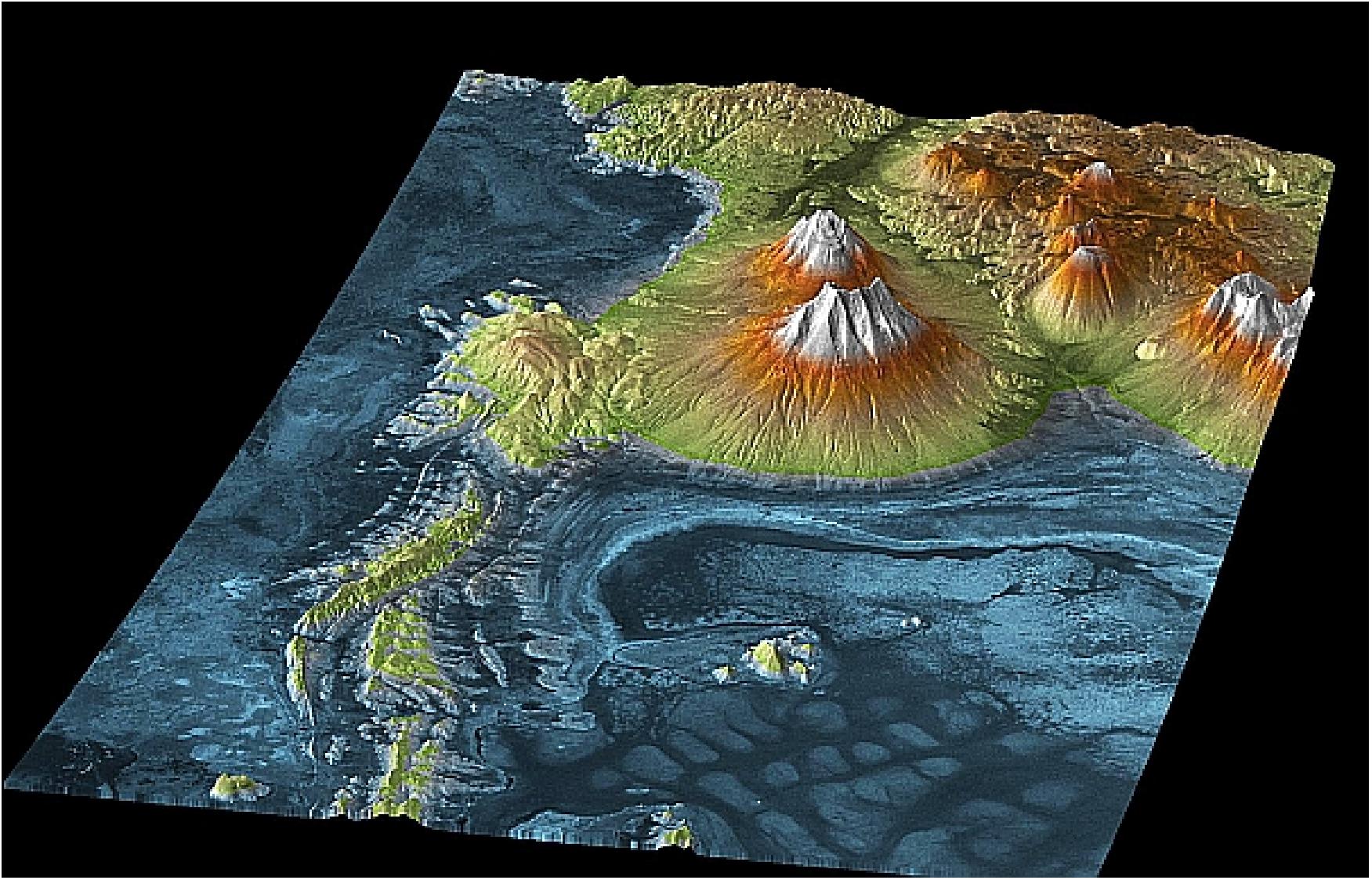
Legend to Figure 45: A digital elevation model from the TanDEM-X mission showing an area on the Kamchatka Peninsula in the northeast of Russia. Wide expanses of the Pacific plate press against the Eurasian plate, causing unique volcanic activity with a very high density of volcanoes. Of the over 160 volcanoes, 29 are currently active and six of them erupt on average each year. Kamchatka is known as the ‘Land of Ice and Fire’ due to its combination of snow and ice and its high level of volcanic activity. Its highest peak is the 4835 m Kliuchevskoi. The simultaneous eruption of four volcanoes (Shiveluch, Bezymianny, Tolbachik and Kizimen) in January 2013 catapulted the region into the headlines. UNESCO declared the volcanic region of Kamchatka a Natural World Heritage Site in 1996.
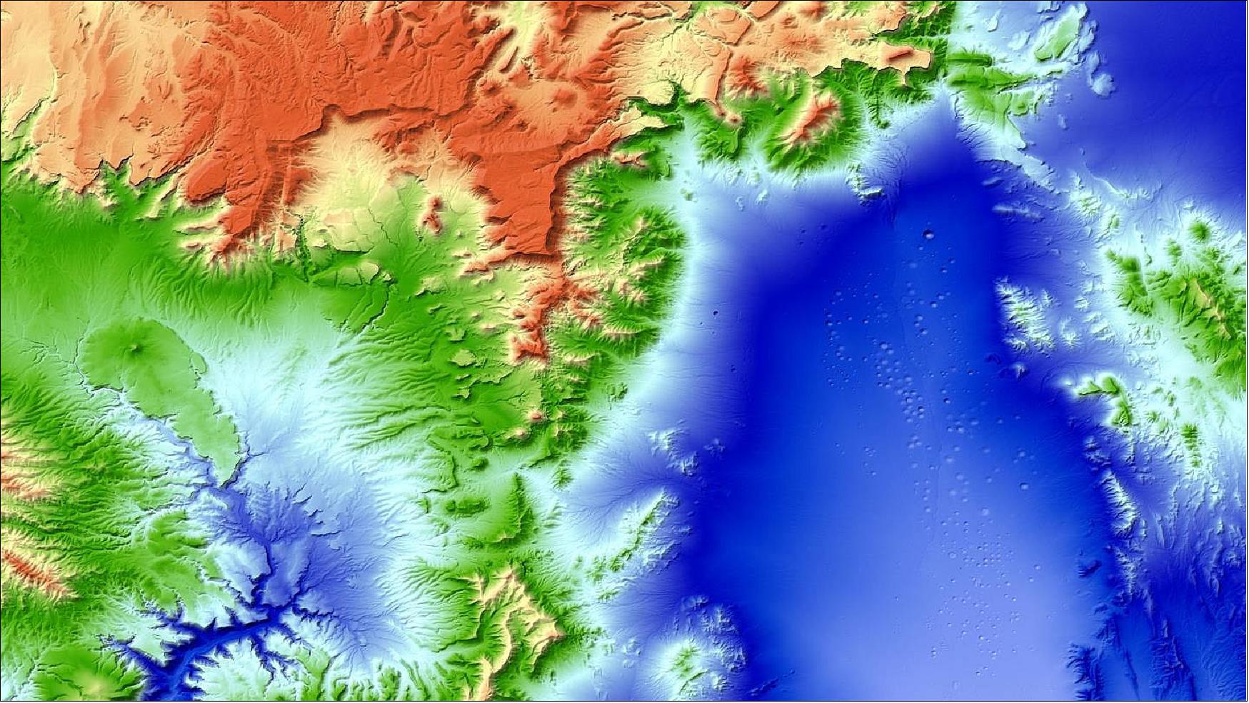
• April 16, 2014: Airbus Defense and Space (former EADS Astrium) has commercially launched WorldDEM™, a Digital Elevation Model (DEM) that provides pole-to-pole coverage of unprecedented accuracy. The new model is based on data acquired by the high-resolution radar satellites TerraSAR-X and TanDEM-X, whose mission is to produce a global DEM at HRTE-3 (High Resolution Terrain Elevation, level-3), representing a significant jump forward in accuracy. In terms of resolution, it is setting new standards by providing 12 m grid spacing globally, compared to 90 m grid spacing on the existing global dataset from SRTM (Shuttle Radar Topography Mission). DLR (German Aerospace Center) is operating the mission and generating the global TanDEM-X DEM as a basis for WorldDEM™. 97)
The 12 m posting product meets a vertical accuracy of 2 m relative and better than 10 m absolute and guarantee full homogeneity and seamlessness. These specifications exceed any other global satellite-based elevation model available today. WorlDEM will improve the performance of worldwide operating systems and cross-border mission planning.
Legend to Figure 46: The WorldDEM™ area south of the city of Quorn in South Australia, Australia shows a diversified terrain with elevations ranging from 9 m to 968 m. The topography is characterized by a large valley with agriculture infrastructure (wheat production) in the eastern part and hilly relief in the western part of the sample.
• February 2014: According to information provided by the TSX/TDX project of DLR, global data acquisition for DEM generation from TSX/TDX will be completed by mid-2014. The processing for the global TSX/TDX DEM is expected to last until early 2016. In early 2014, final DEMs for most of Australia, a large part of North America and Siberia are already available. The brandname or label selected by DLR for the final TSX/TDX DEM is actually called the global TanDEM-X DEM. 99)
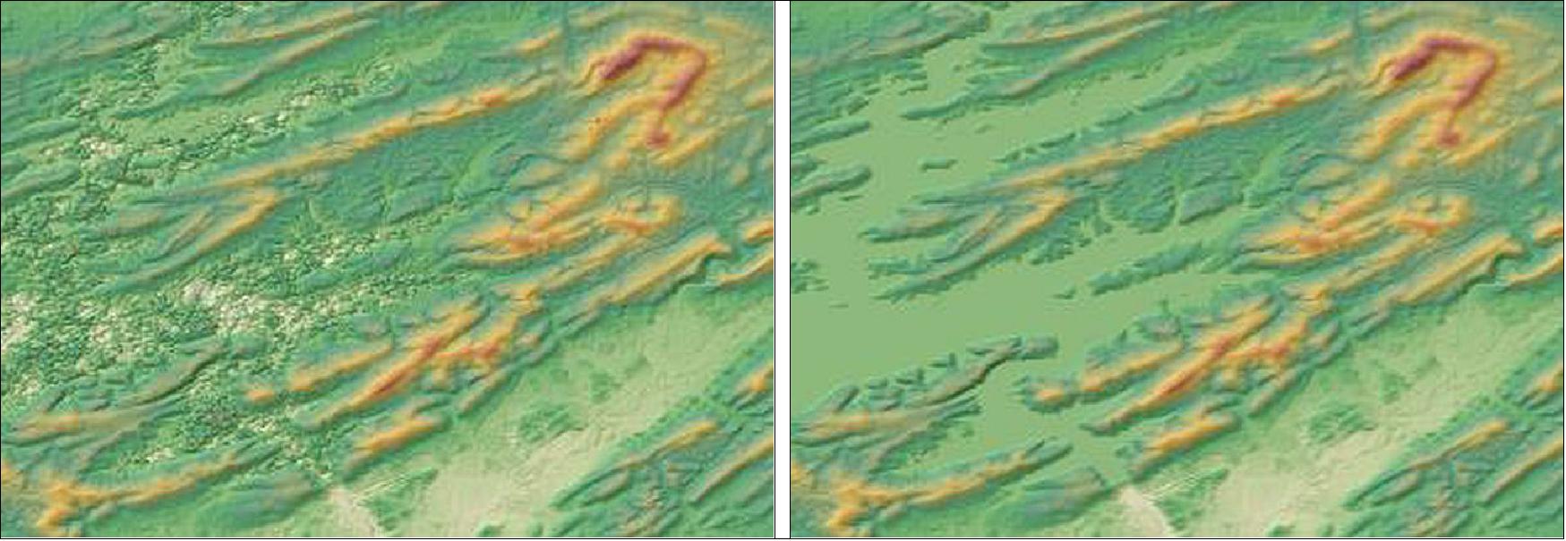
• August 8, 2013: The TanDEM-X mission satellites are reversing their formation to capture challenging terrains, such as mountain ranges, from new angles. The WorldDEMTM, introduced in 2014 by Airbus DS (formerly EADS Astrium Geo-Information Services), aims to replace the SRTM dataset with a global Digital Elevation Model (DEM) of superior quality, accuracy, and coverage. The WorldDEMTM offers a vertical accuracy of 2 meters (relative) and 10 meters (absolute), with a 12 x 12 meter raster and global homogeneity. The model benefits from a 2.5-year initial data collection period and will continue to improve with additional data. Infoterra GmbH manages its commercial marketing, offering various DEM product variants and quality layers, including basic DSMs and edited DSM hydro, with a planned expansion into Digital Terrain Models and other products. 100) 101) 102) 103) 104)
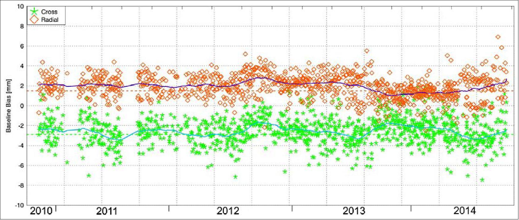
• May 2013: Since December 2010, the TanDEM-X and TerraSAR-X satellites have operated in a close Helix formation at around 514 km altitude, maintaining an 11-day repeat cycle within a 250-meter toroidal tube around a reference trajectory. Initially designed for a three-year mission, the satellites' fuel reserves permit an extended operational period. They have completed two global coverages of Earth's land masses (excluding Antarctica) and are now focusing on challenging terrains, including Antarctica and mountainous regions, with left- and right-looking imaging modes. Accurate baseline determination between the satellites, crucial for achieving the DEM's precision, is achieved using high-grade GPS receivers and sophisticated software, ensuring baseline accuracy within millimeters. The mission has proven capable of meeting its high accuracy goals, facilitating the creation of an unprecedentedly detailed global Digital Elevation Model. 105)
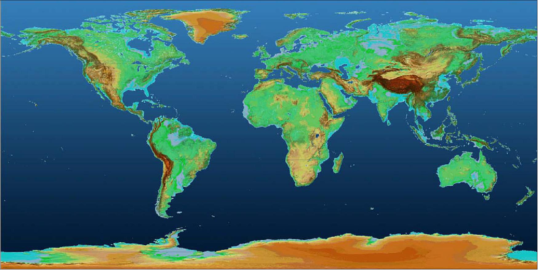
• July 2012: Over the past decade, three significant global topographic mappings have taken place, greatly advancing our understanding of Earth's surface. The Shuttle Radar Topography Mission (SRTM) in 2000 produced the first consistent 30-meter Digital Elevation Model (DEM) between ±60º latitude. Subsequently, NASA's Terra/ASTER system has been generating a near-global 30-meter DEM between ±83º latitude since 2000. Since 2010, the German TanDEM-X mission has been acquiring a global 12-meter DEM with vastly improved resolution and accuracy. Comparisons between TanDEM-X and SRTM DEMs not only highlight expected differences in resolution but also reveal significant changes in Earth's surface over the past decade. Initial accuracy assessments of TanDEM-X data confirm it meets the stringent vertical error specifications, often with just a single coverage. 107)
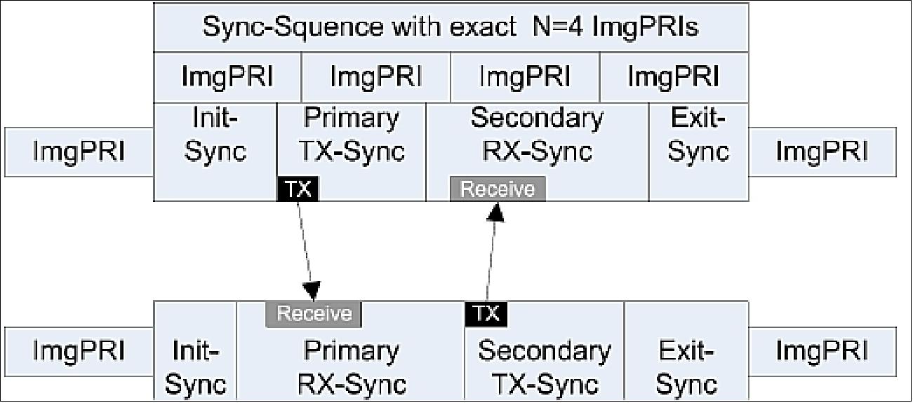
• July 27, 2012: The TanDEM-X mission, comprising the TerraSAR-X (TSX) and TanDEM-X (TDX) satellites, is fully operational, continuing its close formation flight to systematically acquire a global, homogeneous Digital Elevation Model (DEM). Operating primarily in bistatic SAR mode, where one satellite transmits and both receive, the mission supports a range of imaging configurations including along- and cross-track interferometry. The system also enables experimental applications like alternating bistatic acquisition, where the transmission is toggled between the satellites. Precise synchronization between the satellites is achieved through the exchange of specialized synchronization pulses, ensuring accurate timing for fast SAR processing. 108) 109)
• January 2012: After a year of formation flight of TanDEM-X with TerraSAR-X, the twin satellites have completely mapped the entire land surface of Earth for the first time. The data is being used to create the world's first single-source, high-precision, 3D digital elevation model of Earth. DLR controls both radar satellites, generates the elevation model, and is responsible for the scientific use of TanDEM-X data. 110) 111) 112)
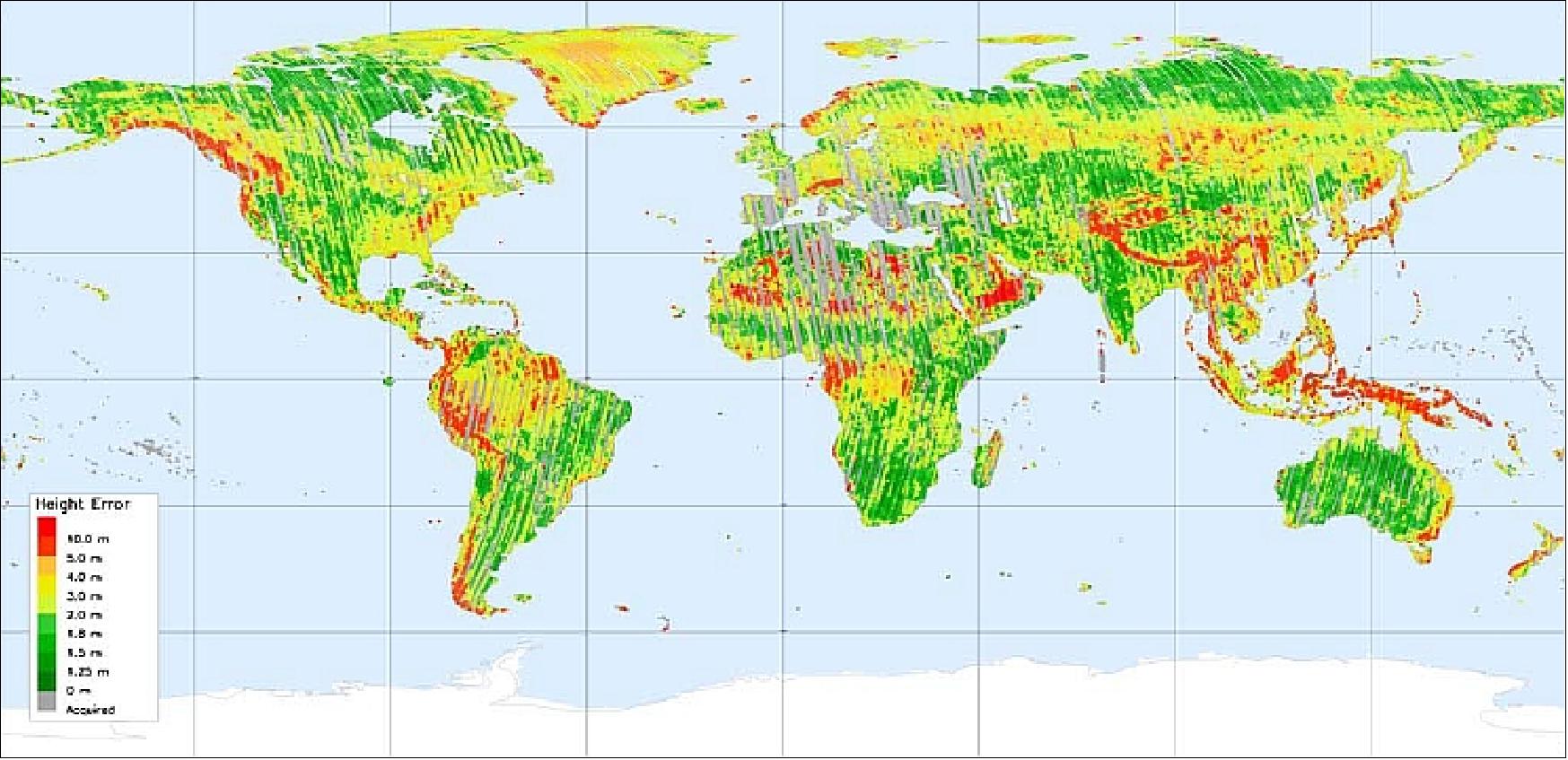
Legend to Figure 48: The color scale of the first global coverage stereo map shows the relative height error (10 m in red to 0 m in dark green) derived from the mean coherence of each individual Raw DEM. Gray-shaded strips have been recorded, but have yet to be processed. 113) 114)
• July 29, 2011: The TanDEM-X mission has made significant progress in its goal to produce a highly accurate global Digital Elevation Model (DEM), having already mapped more than half of the Earth's landmasses. The mission has focused on fine-tuning the processing and calibration of the collected data, ensuring that the TDX satellite performs on par with its counterpart. The performance of TDX has been validated against TSX, with minor differences in noise and power that do not affect the overall imaging quality. The mission's commissioning phase was expedited due to the experience gained from the earlier TerraSAR-X mission, allowing for a quick start to the global DEM acquisition.
The calibration of the SAR system has ensured a geometric offset between the satellites of less than half the wavelength, and a radiometric offset of less than 0.1 dB. Baseline determination, crucial for the height accuracy of the DEM, has reached a relative accuracy of about 1.5 mm, thanks to advanced GPS processing methods. The exact timing and synchronization between the satellites have been fine-tuned to support high-quality bistatic acquisitions, with the baseline calibration activities effectively characterizing and minimizing errors. These technical achievements ensure the mission can meet its stringent height accuracy requirements and deliver high-quality, consistent global elevation data. 115) 125) 126) 127) 128)
Calibration procedure | Goal | TDX | TSX |
Internal calibration |
|
|
|
Antenna pointing knowledge |
|
|
|
Pixel localization accuracy |
|
|
|
Antenna model verification |
|
|
|
Radiometric calibration |
|
|
|
Legend to Table 7: † two-way, †† one-way, * requirement defined over a period of 6 months, ** measured by TSX after 2 years (2009), ‡ StripMap mode.
• March 2011: The TanDEM-X and TerraSAR-X mission continue to acquire bistatic DEM data in their formation flight. So far, no problems in operational handling of bistatic flight configuration and related safety measures were encountered. 116) 117) 118) 119)
• January 2011: The TanDEM-X mission is operational, flying in close formation with TerraSAR-X (a single pass SAR interferometry configuration) and providing stereo SAR imagery. The collection of data for a global homogeneous DEM started as planned in early 2011.
Phase | Description | Date |
Launch |
| June 21, 2010 |
Drift phase to acquire target orbit | The initial separation between TDX and TSX was 15700 km and after one month of drifting a formation in pursuit monostatic configuration with an along-track distance of 20 km was reached. | June 21 - July 22, 2010 |
Wide formation: | TDX monostatic radar instrument commissioning. The wide formation of 20 km was maintained for 3 months to calibrate the TDX radar instruments and to perform first bistatic and interferometric experiments employing large baselines. | July 22 - Oct. 12, 2010 |
Reconfiguration | Both satellites were maneuvered into a close formation to start the bistatic commissioning phase. During this phase, the radial and cross-track baselines were kept constant at 360 and 400 m, respectively, and the mean along-track distance was set to 0 m. The results from both the mono- and bistatic commissioning phase already demonstrated the unique interferometric performance of TanDEM-X. | Oct. 12 - 15, 2010 |
Close formation: | TSX/TDX bistatic instrument commissioning; Begin of routine monostatic radar operation on both satellites | Oct. 15 - Dec. 12, 2010 |
Begin of routine DEM acquisition with flexible baselines: operational phase | Operational DEM acquisition started on December 12, 2010, less than 6 months after satellite launch. Since then, the total landmass of the Earth has been mapped once with a height of ambiguity ranging from 40 to 60 m. Global DEM data acquisition with varying baselines will continue until 2013, mapping difficult terrain like mountains, valleys, tall vegetation, etc., with at least two heights of ambiguity as well as from multiple incidence/aspect angles. The latter will be achieved by swapping the Helix formation. This allows for a shift of the DEM acquisition quadrants from ascending to descending orbits in the northern hemisphere and vice versa in the southern hemisphere. The fully mosaicked DEM shall become available in 2014 for 90 % of the global landmass. | Dec. 12, 2010 |
| In order to collect sufficient measurements for a global DEM (Digital Elevation Model), three years of formation flying are foreseen with flexible baselines ranging from 200 m to a few kilometers. |
|
| Current fuel consumption and battery degradation on the TerraSAR-X satellite is well below specification and will probably allow for life time extensions of two to three years, i.e. close formation flying until 2015 seems feasible. The prolonged mission time will allow for additional DEM acquisitions with improved accuracy and resolution as well as the conduction of advanced bistatic and multistatic SAR experiments in unique configurations, modes and geometries. 120) | Fall 2012 |
The TanDEM-X mission has achieved highly precise relative orbit determination, with position accuracies better than 50 cm in cross-track and about 1 m in along-track directions, enabling effective formation monitoring and control. Following a brief commissioning phase, formation control was fully automated, with daily in-plane maneuvers on TanDEM-X to manage separation and less frequent out-of-plane controls for horizontal adjustments. The achieved control accuracy surpasses mission requirements, with cross-track accuracy of 5 m and along-track accuracy better than 30 m, ensuring the successful acquisition and processing of a global digital elevation model during the mission. 122)
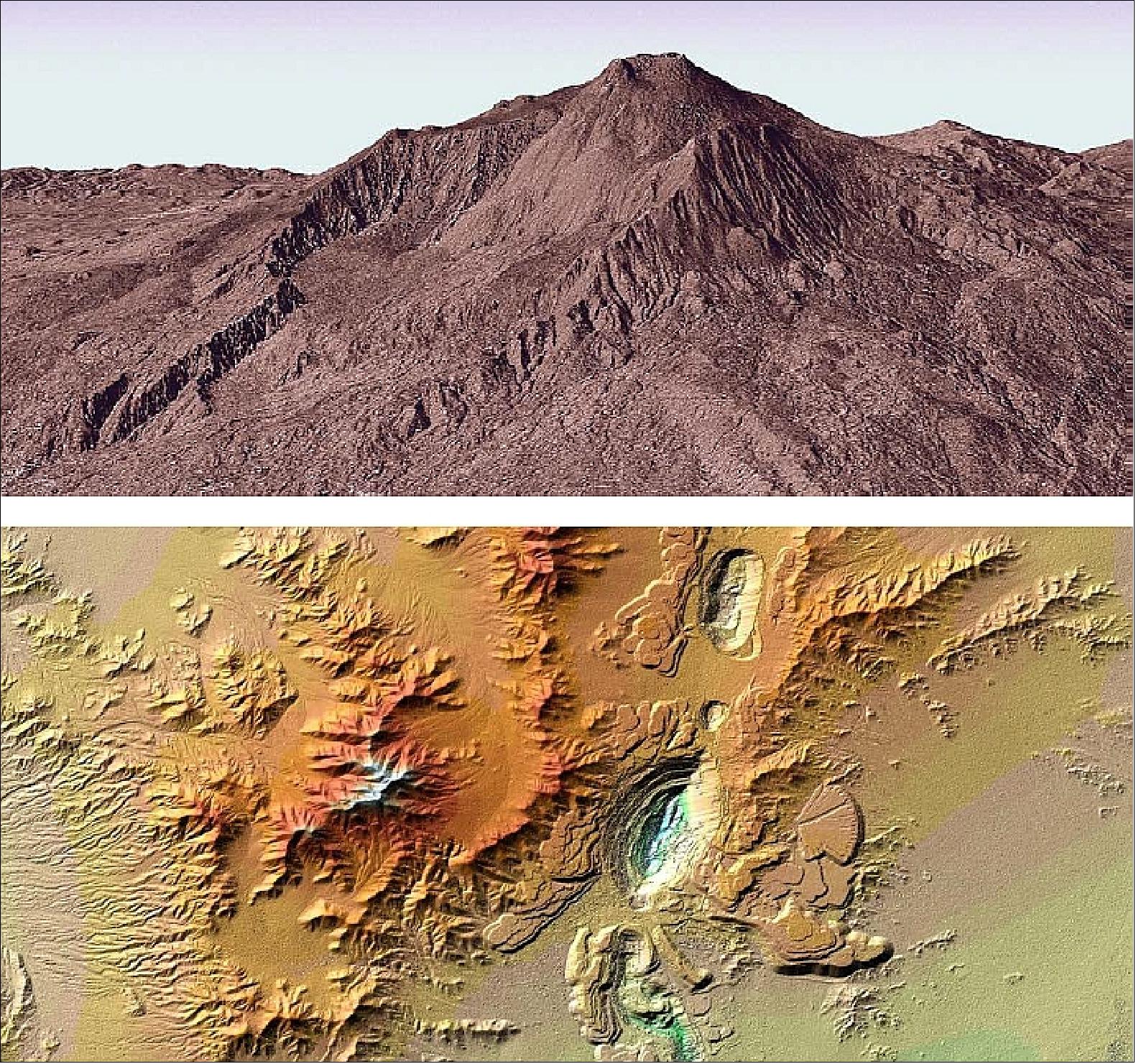
• December 14, 2010: the TanDEM-X mission reached another important milestone: the radar mission's test phase has been concluded in less than six months according to plan, paving the way for routine operations - the collection of elevation data. This meant in particular the start of systematic data acquisition for global DEM generation. 123) 124)
• October 14, 2010: The TanDEM-X (TDX) and TerraSAR-X (TSX) spacecraft are henceforth flying in a close flight formation starting the bistatic commissioning phase. During this phase, the radial and cross-track baselines were kept constant at 360 and 400 m, respectively, and the mean along-track distance was set to 0 m. Bistatic DEMs are being acquired since then. With TDX delivering identical single SAR product quality as TSX, the TerraSAR-X mission is running operationally on both satellites since October 25, 2010.
• October 11, 2010: To enable precise interferometric observations, TanDEM-X and TerraSAR-X were brought into a close formation, reducing their separation from 20 km to just 500 m. TerraSAR-X maintained its circular orbit, while TanDEM-X moved into a slightly eccentric orbit, creating a synchronized, yet intertwined pattern where each satellite alternately overtakes the other at the poles without ever touching. This configuration allows them to fly over the same target area with a minimal time difference, in the range of milliseconds, which is crucial for high-quality interferometric data. 129)
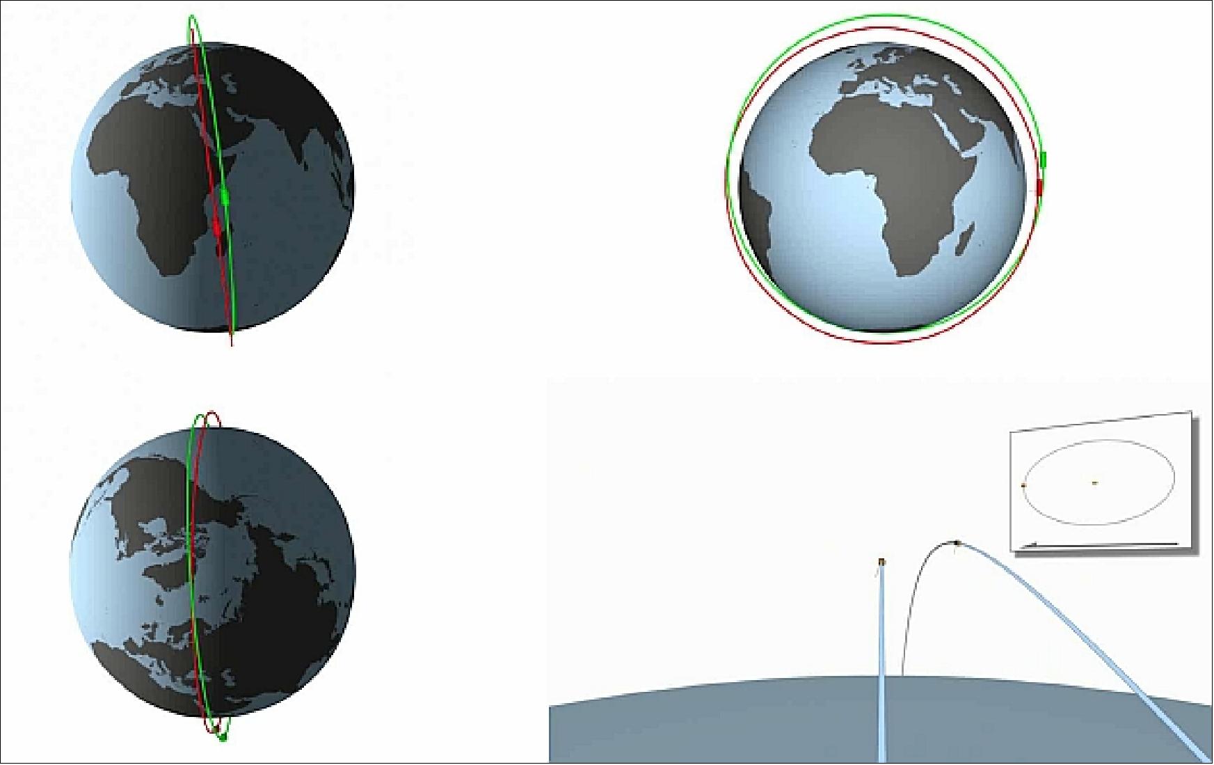
• August 2010: During the monostatic commissioning phase of TanDEM-X, which began in July 2010, the spacecraft achieved a "wide" formation flight with TerraSAR-X, separated by 20 km. This setup allowed for automatic interferometric imagery with a time difference of approximately 3 seconds. During this phase, pioneering bistatic SAR experiments were conducted to evaluate the performance of both space and ground segments under challenging conditions. The first bistatic experiment involved a bistatic acquisition with repeat-pass interferometric processing over Brasília, revealing significant differences in target reflectivity between monostatic and bistatic observations, particularly in urban areas. The repeat-pass bistatic interferogram, processed after 11 days, showed good coherence with minimal differences from the monostatic results.
Following the success of these experiments, a single-pass bistatic interferometric experiment was conducted in October 2010 over Costa Rica's Turrialba Volcano National Park. This experiment aimed to overcome the spectral decorrelation seen in previous configurations by creatively commanding the satellites to switch azimuth antenna patterns on a pulse-to-pulse basis, allowing for coherent images. Despite the need for a higher PRF, which reduced the swath, and the absence of calibration or synchronization pulses, the experiment successfully produced bistatic single-pass interferometric data, marking a significant milestone in the mission. The TAXI processor's automatic synchronization module was crucial in estimating synchronization errors, demonstrating the experiment's scientific value. 130) 131) 132) 133) 134) 135)
Parameter | Experiment 1 | Experiment 2 |
PRF (Pulse Repetition Frequency) | 3182.52 Hz | 2991.24 x 2 Hz |
Incident angle | 36.6º | 35.8º |
Squint angle TSX/TDX | ±0.8º | ±0.9º |
Cross-track baseline | 253 m | 43 m |
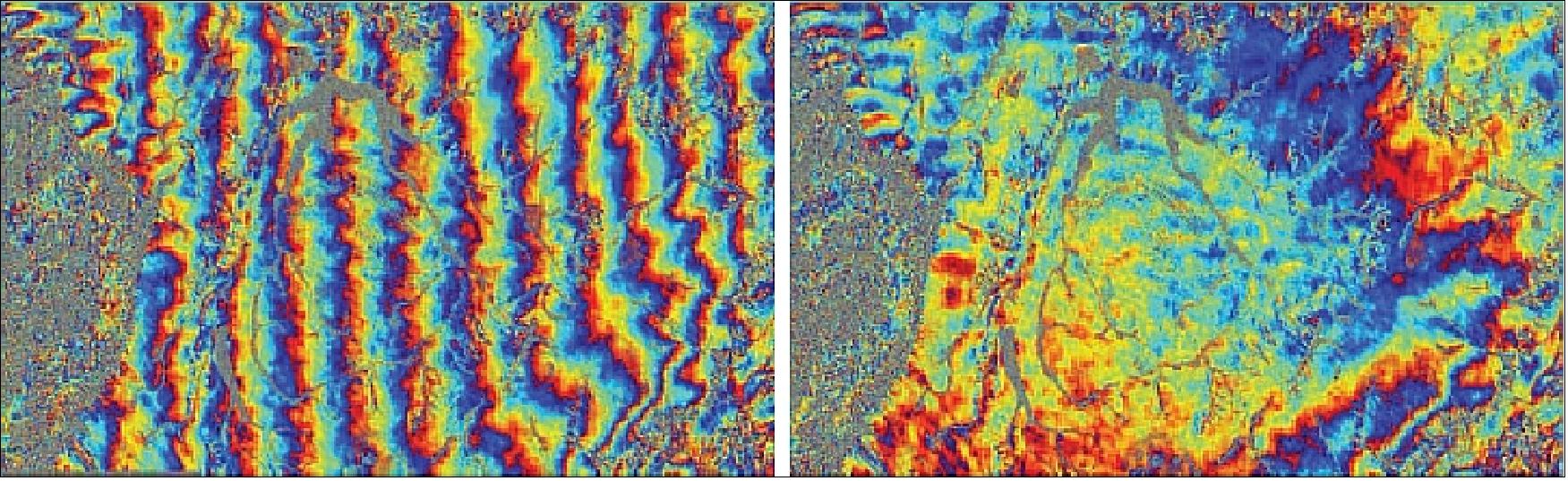
• July 22, 2010: DLR researchers generated the first 3D images from the TanDEM-X mission by capitalizing on a close approach of TanDEM-X and TerraSAR-X in their near-polar orbits on July 16, 2010. Although close formation flying had not yet been achieved, the satellites were brought within 370 km of each other, allowing for the acquisition of interferometric imagery. Despite the 48-second time gap between satellite passes, which led to a ground track separation of over 20 km at the equator, the orbits intersected at the poles, enabling the observation of the same area from similar positions. The resulting digital elevation model of an ice cap on October Revolution Island in the Arctic Ocean was mapped with centimeter-level accuracy, although adjustments were necessary due to Earth's rotation. 136)
The initial separation between TDX and TSX was 15700 km and after one month of drifting a formation with an along-track distance of 20 km was reached (20 km correspond to ~ 3 seconds). This formation was maintained for 3 months to calibrate the TanDEM-X radar instruments and to perform first bistatic and interferometric experiments employing large baselines.
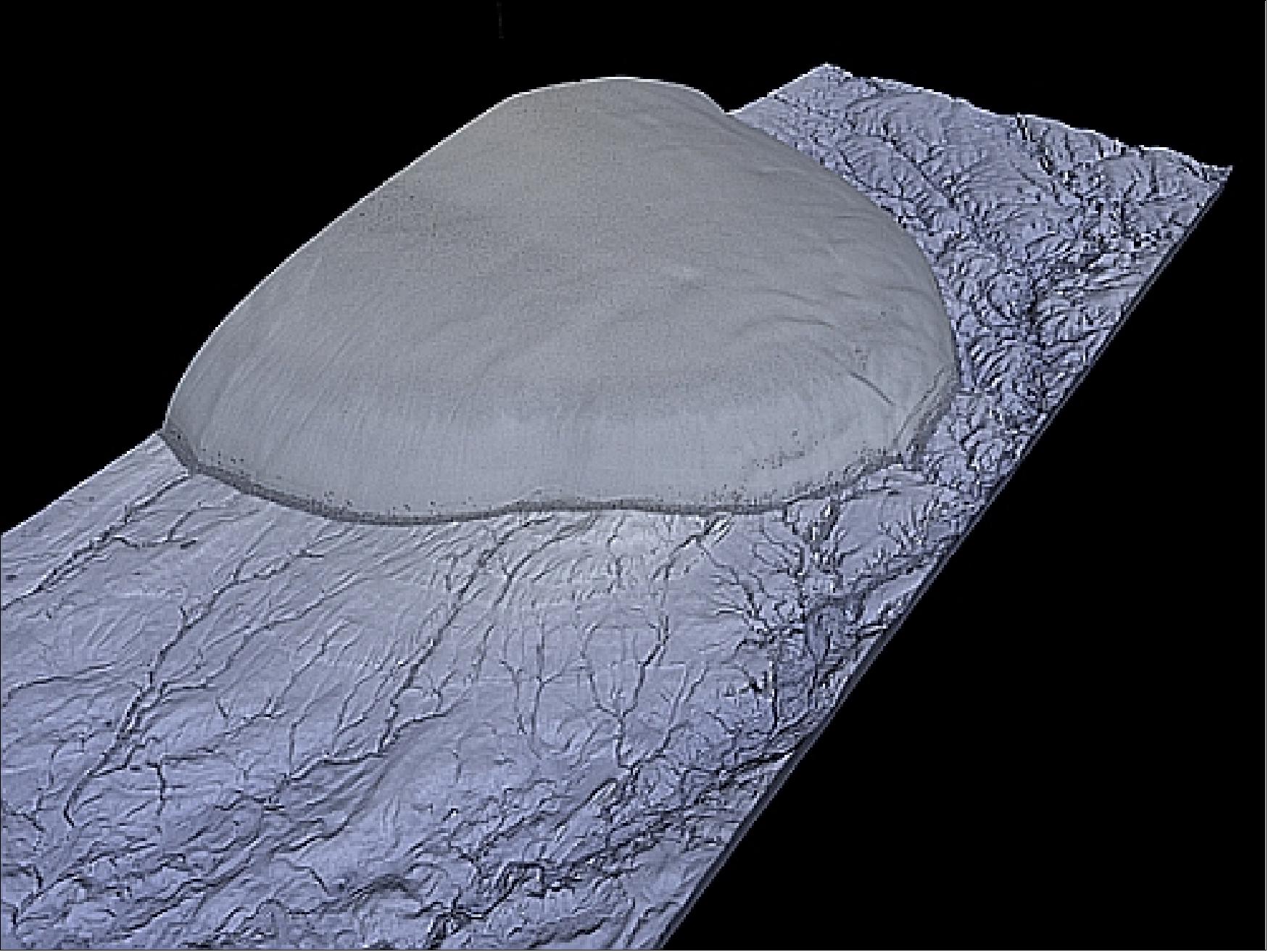
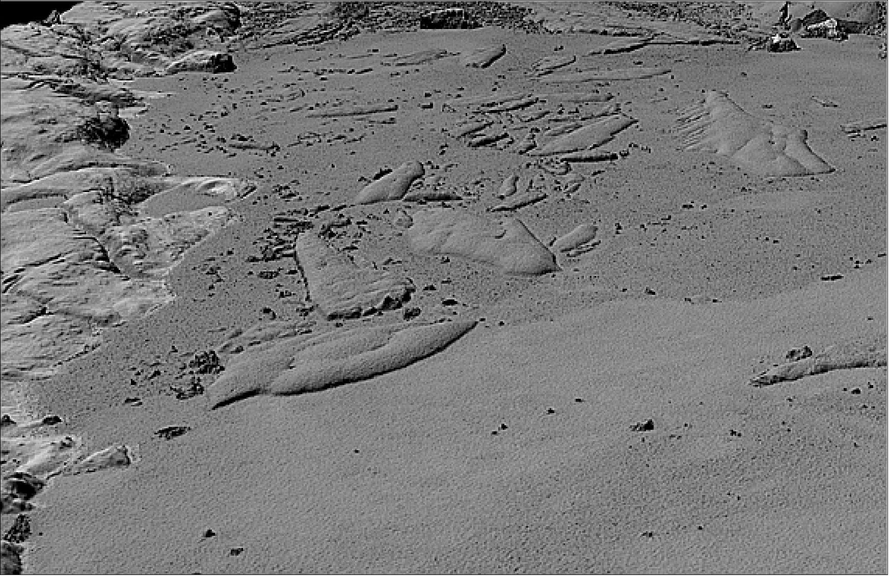
• June 24, 2010: only 3 days into the mission, TanDEM-X sent its first imagery back to Earth. The data transmission was received and automatically processed by the DLR ground station in Neustrelitz, Germany. This ended the LEOP (Launch and Early Orbit Phase) and started the commissioning phase which is expected to last for about 3 months. 137) 138)
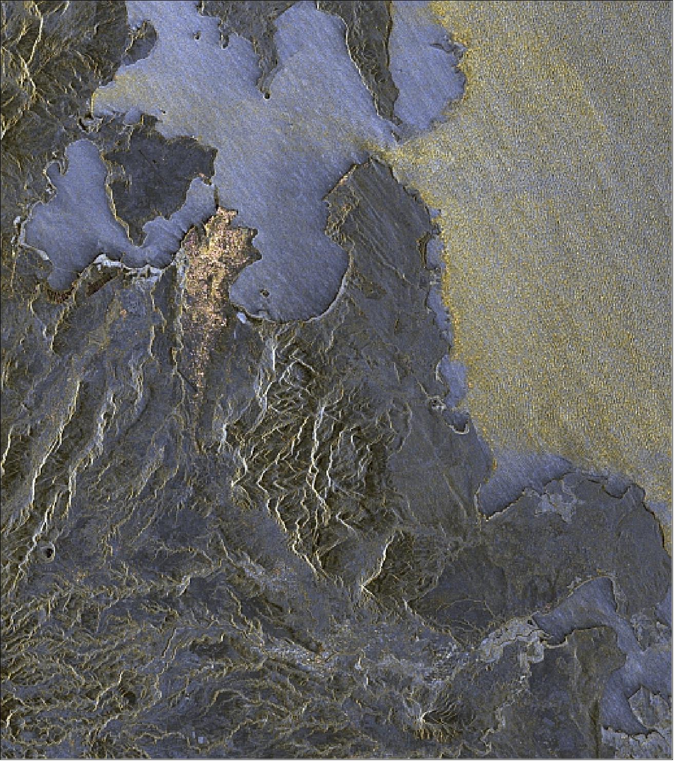
Legend of Figure 56: The pale yellow areas on the right side of the image depict the waves of the Indian Ocean, with a noticeable change in wave patterns at the entrance to Diego Suarez Bay. The flat, reflective water within the bay, where the provincial capital city Antsiranana is situated, contrasts sharply with the surrounding ocean's undulating surface. The image also highlights the drainage of the volcanic cone of Ambre-Bobaomby into the Indian Ocean through the southern valleys.
• A first signal of the TanDEM-X spacecraft was received via the Troll ground station in Antarctica. TrollSat is Norway's 7.5 m X-band ground station of KSAT (Kongsberg Satellite Services AS) in Antarctica (72º S, 2º E, since 2007) operated from Tromsø, Norway.
Sensor Complement
The TDX-SAR instrument is identical to the TSX-SAR (TerraSAR-X SAR instrument) in layout, operational performance and support modes. Hence, the reader is referred to the TSX-SAR instrument description of the TerraSAR-X mission.
Each spacecraft in the formation is equipped with 6 small horn antennas that are used to exchange X-band synchronization pulses with a frequency of about 10 Hz. This allows for a phase synchronization with an accuracy in the order of 1º.
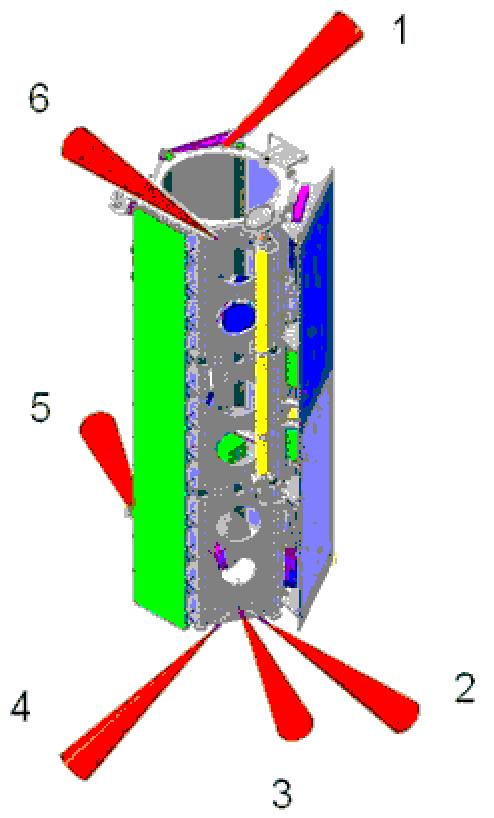
The intersatellite X-band synchronization is established by a mutual exchange of radar pulses between the two satellites. For this information exchange, the nominal bistatic SAR data acquisition is shortly interrupted, and a radar pulse is redirected from the main SAR antenna to one of six dedicated synchronization horn antennas mounted on each spacecraft. The pulse is then recorded by the other satellite which in turn transmits a short synchronization pulse. This trigger establishes the bidirectional link between the two radar instruments which allows for mutual phase referencing without the exact knowledge of the actual distance between the satellites.
The TanDEM-specific SAR instrument features provide a scheme for transmission and reception of USO (Ultra Stable Oscillator) phase information between the SAR instruments with adequate SNR (at X-band for low atmospheric sensitivity). The synchronization horn antennas are connected to the unused polarization inputs/outputs of the leaf amplifier assembly TRMs. The major driver was to find a suitable accommodation (see Figure 57) and RF-design of the horns to give full solid-angle coverage with low phase disturbance. The data take start time accuracy has to be improved (relative to onboard GPS time) to allow for synchronization of data takes of both SARs. These modifications have already been implemented on the TerraSAR-X spacecraft.
Note: The TSX-SAR is already built for repeat pass interferometry and thus provides several essential features for the TanDEM-X mission, like precise orbit control, a single-frequency GPS for orbit determination, and excellent RF phase stability.
Parameter | Value | Parameter | Value |
Satellite orbit altitude | 514 km | Antenna length | 4.8 m |
Nominal swath width | 30 km | Antenna width | 0.7 m |
Swath overlap | 6 km | Antenna elements | 32 x 12 |
Carrier frequency | 9.65 GHz | Antenna tapering | Linear phase |
Chirp bandwidth | 100 MHz | Antenna mounting | 33.8º |
Sampling frequency | 110 MHz | Data quantization | 3 bit/sample |
Peak Tx power | 2.26 kW | Image pair misregistration | < 0.1 pixel |
Duty cycle | 18% | Proc. azimuth bandwidth | 2266 Hz |
Noise figure TRM | 4.3 dB | Misregistration | 0.1 pixel |
Losses (proc., atm., taper, degradation) | 3.1 dB | Sigma nought (σο) model (Ulaby, 90%, X-band) | Soil and rock, VV |
Independent post spacing | 12 m x 12 m | Along-track baseline | < 1 km |
RF center frequency | 9.65 GHz (X-band, 3.1 cm wavelength) |
Bandwidth | up to 300 MHz |
Incidence angle range | 20º to 55º |
Polarization | single, dual, quad |
SAR modes | Stripmap, ScanSAR, Spotlight, |
Regarding the X-SAR instrument on TDX, several optimizations were performed to further improve the producibility of the TRM (T/R Module) and to guarantee the excellent quality reached with the TSX TRMs. 139)
Secondary Payloads
TOR (Tracking, Occultation and Ranging)
TOR, a dual-frequency GPS flight receiver with two zenith antennas for POD (Precise Orbit Determination) applications support, is of TerraSAR-X heritage provided by GFZ Potsdam and CSR (Center of Space Research) of the University of Texas at Austin.
- The excellent data provided by the TOR device flown on the TerraSAR-X mission led to the decision to duplicate this instrument for TanDEM-X. The additional TanDEM-X requirement of intersatellite baseline determination between both satellites with mm accuracy is essential for the success of the anticipated generation of global DEMs (Digital Elevation Models). 140)
The TOR payload consists of the dual-frequency GPS receiver IGOR (Integrated GPS Occultation Receiver), developed and built by Broad Reach Engineering Company of Tempe, AZ, and LRR (Laser Retro Reflector) for evaluation of GPS-based orbit data as an independent tracking technique. - The general description of TOR and LRR is provided under the TerraSAR-X mission.
LCT (Laser Communication Terminal)
LCT is again of Tesat-Spacecom GmbH manufacture and a contribution in kind of DLR. The objective of LCT on TanDEM-X is to demonstrate and verify the performance of a 2 Gbit/s optical LEO-to-GEO link as part of an experimental broadband data relay transmitting a 300 Mbit/s user data stream from TanDEM-X to ground. 141) 142)
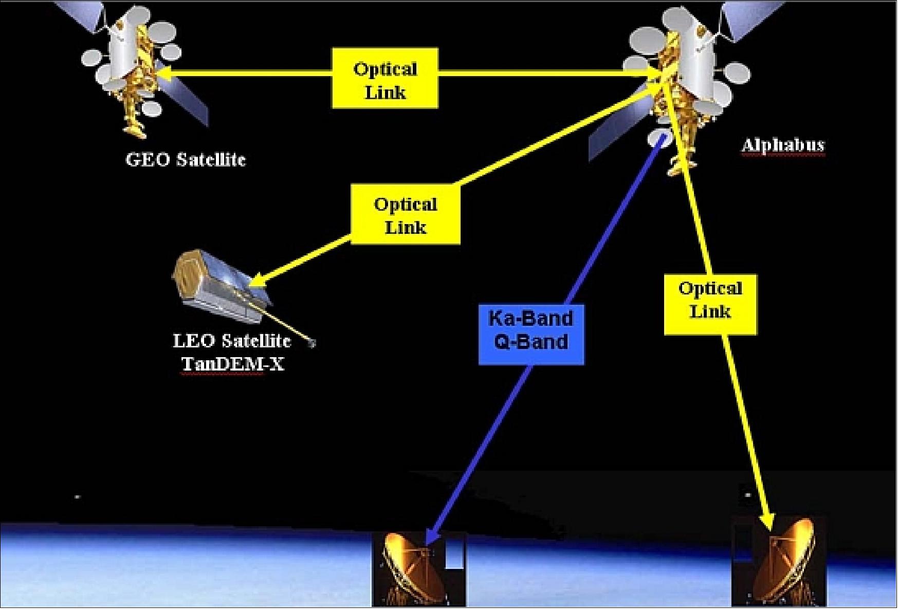
Compared to the TerraSAR-X mission, the enhanced TanDEM-X LCT terminal allows optical laser links to a relay satellite in the geostationary orbit. The technology demonstration of optical high data rate intersatellite links and the subsequent Ka-band downlink is important to cope with the increased demand of data downlink capacity in future EO missions (LCTs are being planned to support the European GMES program missions). 143)
Homodyne binary phase shift keying (BPSK) is based on coherent detection, i.e. the signal to be detected is superposed to a local oscillator laser running on the same frequency as the signal's carrier. - The general description of LCT is provided under the TerraSAR-X mission.
TDX/TSX Applications
Beyond the global HRTI-3 DEM as the primary mission objective, TanDEM-X will demonstrate several enabling technologies like: VLBI (Very Large Baseline Interferometry), along-track interferometry, polarimetric SAR interferometry, four phase center moving target indication, bistatic SAR imaging, and digital beamforming.
• The VLBI concept takes advantage of the large bandwidth of the TSX-SAR instrument to significantly improve the height accuracy for local areas by combining multiple interferograms with different baseline lengths. This can e.g. be used to acquire DEMs with HRTI-4 like quality on a local or even regional scale. A temporal comparison of multiple large baseline TanDEM-X interferograms (either phase or coherence) provides furthermore a very sensitive measure for vertical scene and structure changes. 144)
• Along-track SAR interferometry can either be performed by the so-called dual receive antenna mode with a baseline of 2.4 m from each of the satellites or by adjusting the along-track distance of the two satellites to the desired size (Figure 59). The HELIX orbit concept allows this distance (called along-track baseline) to be adjusted from zero to several kilometers. This technical feature is essential as this application requires velocity measurements of different fast and slow objects. Mainly four scientific application areas are identified to explore the innovative along-track mode: oceanography, traffic monitoring, glaciology and hydrology.
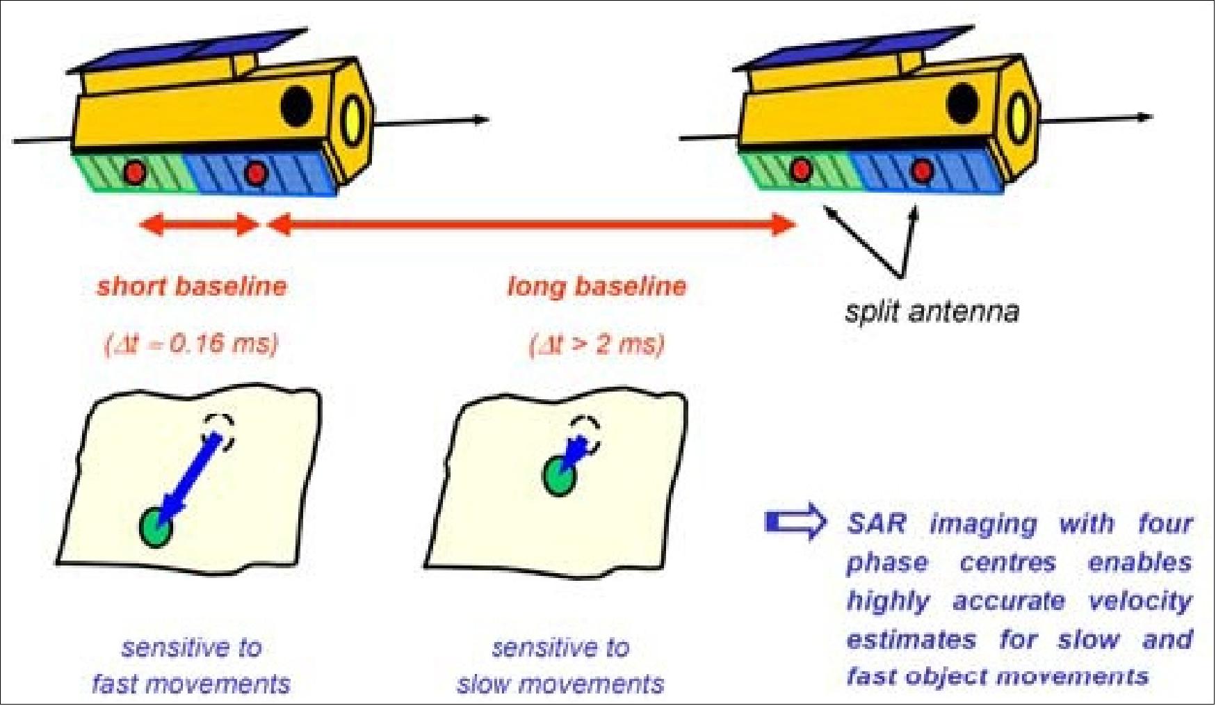
• Polarimetric SAR Interferometry combines interferometric with polarimetric measurements. This allows e.g. for the extraction of vegetation density and vegetation height. Fully polarimetric operation uses the split antenna and is susceptible to ambiguities which limit the swath width. This could be avoided by a restriction to dual polarized measurements and/or an acquisition of multiple polarizations in successive passes.
• Bistatic Imaging provides additional observables for the extraction of new scene and target parameters. A combination of bistatic and monostatic images can e.g. be used to improve segmentation, classification and detection. Data takes with large bistatic angles are planned at the beginning and end of the TanDEM-X mission.
• The TerraSAR-X/TanDEM-X mission will be the first operational mission requiring a post-facto baseline reconstruction with an accuracy of 1 mm. The feasibility of achieving this goal using GPS dual-frequency measurements of the IGOR GPS receiver has earlier been demonstrated in the GRACE mission.
• Digital beamforming (DBF) and super resolution techniques can be used to suppress ambiguities and to enhance the ground resolution. The combination of the four independent phase centers in TSX and TDX enables also a first demonstration of high resolution wide swath (HRWS) SAR imaging.
With TanDEM-X, innovative SAR techniques will be demonstrated and exploited, which open up new perspectives for future SAR systems. The focus will be on the following application areas and the associated application topics:
Application area | Application topics |
Cross-track SAR interferometry | |
Land environment | Navigation, Crisis and security management, Urban areas, |
Glaciology/hydrology | Ice and snow, Sea-ice, Morphology/hydrology |
Geology | Geological mapping/morphology, Earthquakes/volcanoes, Landslides, Subsidence (land and urban areas) |
Land cover and vegetation | Land cover/surface parameters, Forestry, |
Oceanography | Wind and waves/ocean dynamics, Ship detection, Coastal zones |
Along-track SAR interferometry | |
Oceanography | Ocean currents, Coastal zones, Ship detection, Wind and waves |
Traffic | Traffic flow monitoring, Development of new SAR techniques |
Glaciology | Ice flow monitoring |
Hydrology | River flow monitoring, Development of new SAR techniques |
New SAR techniques | |
Multistatic processing | Bistatic/multistatic processing, Land cover, Development of new SAR techniques |
Pol-InSAR (polarimetric SAR interferometry) | Forest, Agriculture, Snow and ice, Ship detection, Wind and waves, Geological mapping, Urban areas, Landslides/subsidence, Earthquakes/volcanoes, Development of new SAR techniques |
Digital beam forming (DBF) | Wide swath imaging and ambiguity suppression, Development of new SAR techniques |
Super resolution | Development of new SAR techniques |
InSAR processing | Development of new SAR techniques, Ultra high resolution DEM with multiple baselines |
Formation flying | Development of new SAR techniques, Precise baseline determination and orbit control |
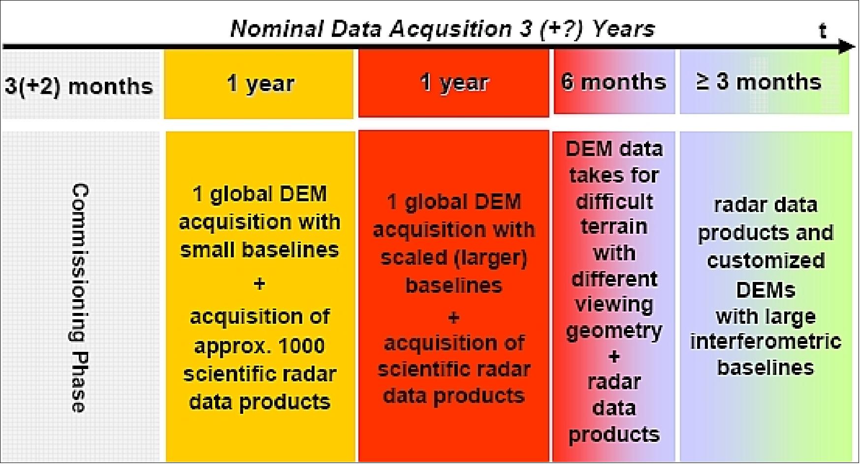
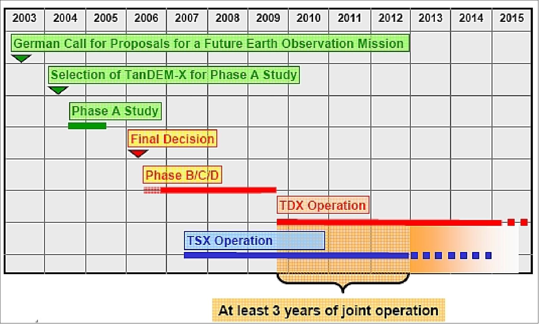
Ground Segment
The TanDEM-X and TerraSAR-X missions are closely linked and share resources of the space and ground segments. Consequently, for the overall TanDEM-X system, besides the additional TanDEM-X satellite, the TerraSAR-X ground segment has to be extended. The ground segment consists of three major parts all covered by DLR: 145) 146)
• MOS (Mission Operations Segment) to simultaneously operate two satellites in close formation and to optimally merge the acquisition plans for both missions. The MOS service is provided by the German Space Operation Center (GSOC).
• PGS (Payload Ground Segment) to handle the increased data volume, to include a network of receiving stations, to adapt the processing chain for new data products and to generate the global HRTI-3 DEM. The PGS service is provided by the German Remote Sensing Data Center (DFD) and the Remote Sensing Technology Institute (IMF).
• IOCS (Instrument Operations and Calibration Segment) to operate the two SAR sensors in bistatic mode including synchronization, to calibrate and validate interferometric products. The IOCS service is being provided by the Microwaves and Radar Institute (IHR).
The GFZ (Geoforschungszentrum) Potsdam is responsible for the IGOR data analysis for precise baseline determination.
The scientific exploitation of the TanDEM-X data is coordinated by the DLR Science Service Segment. Commercial customers are served by Infoterra GmbH.
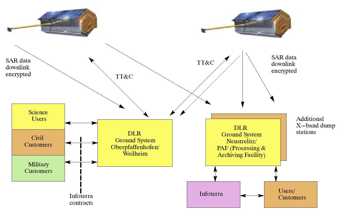
The ground stations for data reception are: 147)
- Neustrelitz, Germany (DLR station)
- Weilheim, Germany (DLR station)
- GARS (German Antarctic Receiving Station) at O’Higgins in Antarctica with 9 m L/S/X-band antenna
- Inuvik, NWT (Northwest Territories), Canada: DLR station with 13 m L/S/X-band antenna. Inuvik is a CCRS-controlled facility located just outside the town of Inuvik (68º 19’ N; 133º 32’ W). On August 10, 2010, DLR inaugurated the new Inuvik station for TanDEM-X use. 148) 149) 150) 151) 152)
The Inuvik station is fully automated, from antenna control, through the complete reception chain, to the recording of the encrypted raw data onto tape. These tapes are then sent to DLR for processing. Monitoring of the station operations is performed at the Earth Observation Center in Oberpfaffenhofen, where all the data from the various TanDEM-X ground stations comes together and is assessed for completeness and quality.
- ERIS Chetumal, Mexico (Yucatan Peninsula): DLR transportable ground station with L/S/X-band 9 m antenna (ERIS = Estacion para la Reception de Imagenes Satelitales).
- Kiruna, Sweden, a partner ground station of SSC (Swedish Space Corporation).
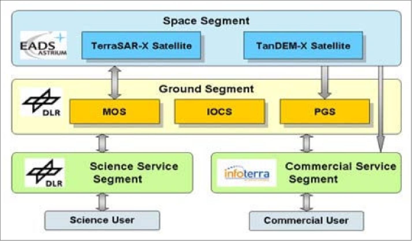
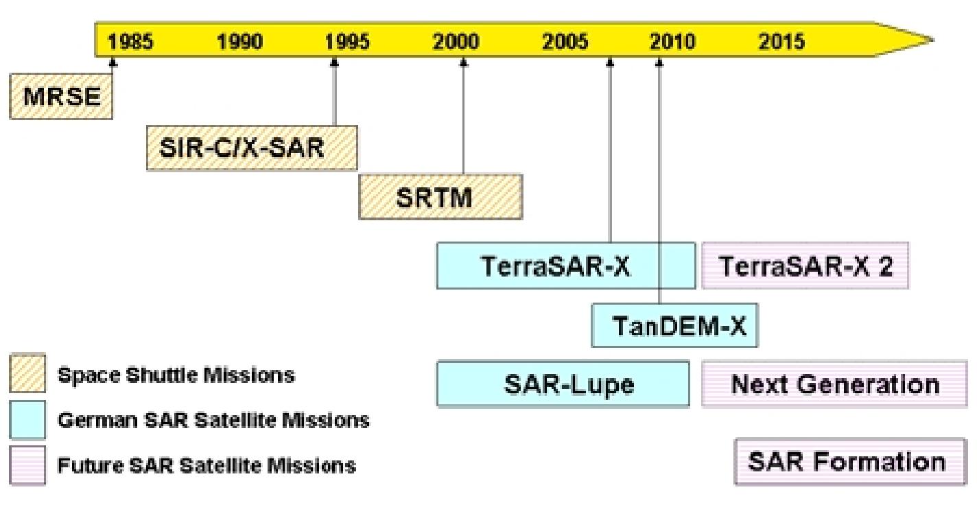
SAR products | DEM products |
Experimental products from operational modes (co-registered complex images –“CoSSCs”) | HRTI-3 specified DEM |
Experimental mode raw data (processing with help from DLR contact scientist) | Intermediate DEM: close to HRTI-3 specified DEM |
TS-X mission basic products* from selected TanDEM-X raw data sets | FDEMs: DEMs processed to finer pixel spacing and higher random height error |
“Byproduct“ of operational DEM processing chain: archive of CoSSCs from all acquisitions for DEM generation (multi-temporal global coverage) | HDEMs: HRTI-4 like DEMs (high resolution DEM, were additional acquisitions are needed) |
Dual Satellite and Dual Mission Operations Concept: 153)
The basic operations concept is to handle TSX and TDX operations independently as far as possible. TSX and TDX spacecraft are nearly identical from hard- and soft-ware point of view. There is no master/slave configuration between both spacecraft but an equal level operations approach. Figure 65 shows a simplified work flow for TSX and TDX operations in the control center. Each satellite, TSX and TDX, has a dedicated TT&C link from ground to space. There is no telecommand routing from one spacecraft to the other and also no complete telemetry routing.
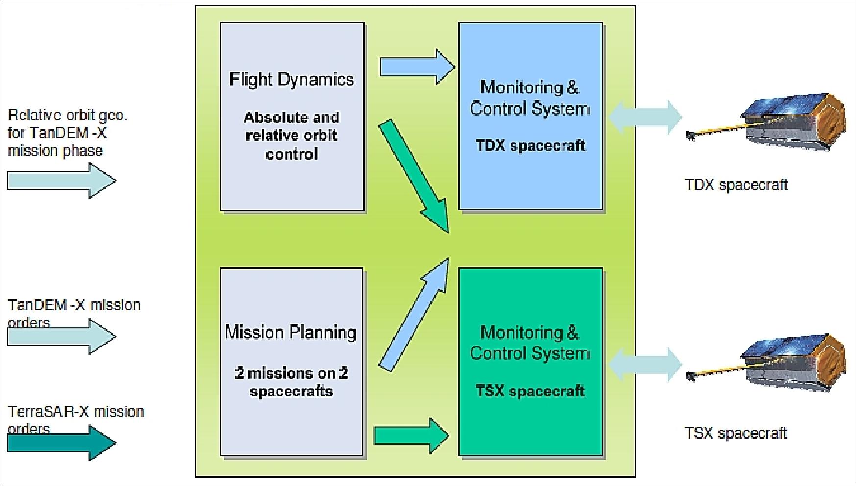
Legend to Figure 65: The green box summarizes elements being part of the Control Center. TDX and TSX space craft are each controlled by a satellite specific monitoring & control system. The elements Mission Planning and Flight Dynamics are combined systems for both satellites, generating output to both monitoring & control systems. The Mission Planning System receives external orders from the TerraSAR-X mission and the TanDEM-X mission. Relative orbit control performed by Flight Dynamics is based on the required geometry of the TanDEM-X mission phase.
GSCDA (GMES Space Component Data Access)
The GMES Space Component (GSC) includes the Sentinel satellites and the coordinated access to ESA and European EO missions.
In 2007, ESA and the EC (European Commission) signed an agreement to allow ESA to ensure the coordinated and timely supply of satellite-based Earth Observation data for the preoperational phase of GMES from 2008 to 2010.
ESA is managing the GSCDA project in the frame of the FP7 space program as part of the European Space Policy focusing on coordinating the access to space-based observation data to support GMES services.
ESA targets the introduction of the following capabilities to achieve a coordinated access to data from current and future missions:
• HMA (Heterogeneous Mission Access). GMES data access implies also a coherent data access to ~40 different EO missions (inside and outside of ESA). Aside from the current and future ESA missions (Envisat, GOCE, SMOS, CryoSat-2, MSG-3, Swarm, ADM/Aeolus, GMES Sentinels, etc.), the European space agencies are also cooperating with their EO missions to make HMA become possible for a global EO community. 154)
• QA4EO (Quality Assurance Framework for Earth Observation data). 155)
• LTDP (Long Term Data Preservation). 156)
DLR is a cooperative member of the GSCDA initiative. The ground segment of the missions TerraSAR-X (launch June 15, 2007), TanDEM-X (launch planned for Oct. 2009), and EnMAP (launch 2013) are part of GSCDA (implementation of HMA customization). The GSCDA/HMA feature will be made compatible through the DLR DIMS-based (Data and Information Management System) catalog/archive. 157)
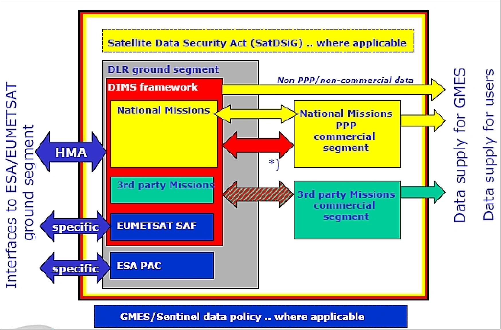
References
1) G. Krieger, A. Moreira, I. Hajnsek, M. Werner, H. Fiedler, E. Settelmeyer, “The TanDEM-X Mission Proposal,” Proceedings of the ISPRS Hannover Workshop 2005, Hannover, Germany, May 17-20, 2005
2) G. Krieger, H. Fiedler, I. Hajnsek, M. Eineder, M. Werner, A. Moreira, “TanDEM-X: Mission Concept and Performance Analysis,” Proceedings of IGARSS 2005, Seoul, Korea, July 25-29, 2005
3) G. Krieger, A. Moreira, H. Fiedler, I. Hajnsek, M. Eineder, M. Zink, M. Werner, “TanDEM-X: A Satellite Formation for High Resolution SAR Interferometry,” FRINGE 2005 Workshop, ESA/ESRIN, Frascati, Italy, Nov. 28-Dec. 2, 2005, URL: http://earth.esa.int/fringe2005/proceedings/papers/382_krieger.pdf
4) M. Zink, G. Krieger, H. Fiedler, I. Hajnsek, A. Moreira, M. Werner, “TanDEM-X: The First Bistatic SAR Formation in Space,” Proceedings of the Advanced RF Sensors for Earth Observation 2006 (ASRI), Workshop on RF and Microwave Systems, Instruments & Sub-Systems, ESA7ESTEC, Noordwijk, The Netherlands, Dec. 5-6, 2006
5) M. Weber, J. Herrmann, I. Hajnsek, A. Moreira, “TerraSAR-X and TanDEM-X: Global Mapping in 3D using Radar,” URL: http://www.isprs2007ist.itu.edu.tr/22.pdf
6) http://www.dlr.de/Portaldata/32/Resources/dokumente/tdmx/TDX_Science_Meeting_No_1.pdf
7) Johannes Böer, Hauke Fiedler, Gerhard Krieger, Manfred Zink,, Markus Bachmann,, Jaime Hueso Gonzalez, “TanDEM-X: A Global Mapping Mission,” FIG Working Week 2008, Stockholm, Sweden, June 14-19, 2008, URL: http://www.fig.net/pub/fig2008/papers/ts01h/ts01h_03_boer_etal_3033.pdf
8) M. Bartusch, H. J. Berg, O. Siebertz, “The TanDEM-X Mission,” Proceedings of EUSAR 2008, 7th European Conference on Synthetic Aperture Radar, June 2-5, 2008, Friedrichshafen, Germany
9) Gerhard Krieger, Alberto Moreira, Hauke Fiedler, Irena Hajnsek, Marian Werner, Marwan Younis, Manfred Zink, “TanDEM-X: A Satellite Formation for High-Resolution SAR Interferometry,” IEEE Transactions on Geoscience and Remote Sensing, Vol. 45, No 11, Nov. 2007, pp. 3317-3341
10) Nestor Yague-Martinez, Michael Eineder, Ramon Brcic, Helko Breit, Thomas Fritz, “TanDEM-X Mission: SAR Image Coregistration Aspects,” Proceedings of EUSAR 2010, 8th European Conference on Synthetic Aperture Radar, June 7-10, 2010, Aachen, Germany
11) “TanDEM-X: Mapping the world in 3D,” Dec. 16, 2010, URL: https://web.archive.org/web/20110923195253/http://www.astrium.eads.net/en/news2/tandem-x-mapping-the-world-in-3d.html
12) G. Krieger, A. Moreira, H. Fiedler, I. Hajnsek, M. Zink, M. Werner, M. Eineder, “TanDEM-X: Mission Concept, Product Definition and Performance Prediction,” Proceedings of EUSAR 2006, Dresden, Germany, May 16-18, 2006
13) H. Fiedler, G. Krieger,M. Zink, M. Geyer, J. Jäger, “The TanDEM-X Acquisition Timeline and Mission Plan,” Proceedings of EUSAR 2008, 7th European Conference on Synthetic Aperture Radar, June 2-5, 2008, Friedrichshafen, Germany
14) H. Fiedler, G. Krieger, M. Werner, K. Reiniger, M. Eineder, S. D' Amico, D. Erhardt, M. Wickler, “The TanDEM-X Mission Design and Data Acquisition Plan,” Proceedings of EUSAR 2006, Dresden, Germany, May 16-18, 2006
15) I. Hajnsek, A. Moreira, “A TanDEM-X : Mission and Science Exploration during the Phase A Study,” Proceedings of EUSAR 2006, Dresden, Germany, May 16-18, 2006
16) A. Moreira, G. Krieger, I. Hajnsek, D. Hounam, M. Werner, S. Riegger, E. Settelmeyer, “TanDEM-X: A TerraSAR-X Add-On Satellite for Single-Pass SAR Interferometry,” Proceedings of IGARSS 2004, Anchorage, AK, USA, Sept. 20-24, 2004, URL: http://www.dlr.de/hr/Portaldata/32/Resources/dokumente/tdmx/TanDEM-X-IGARSS-2004.pdf
17) M. Younis, G. Krieger, H. Fiedler, I. Hajnsek, M. Werner, M. Zink, A. Moreira, “TanDEM-X: A Satellite Formation for High-Resolution Radar Interferometry,” Proceedings of the International Radar Symposium 2007 (IRS 2007), Cologne, Germany, Sept. 5-7, 2007
18) H. Fiedler, M. Zink, G. Krieger, A. Moreira, “The TanDEM-X Mission: Overview and Status,” Fringe 2007 Workshop - space radar advances and applications with a focus on radar interferometry, ESA/ESRIN, Nov. 26-30, 2007, URL: http://earth.esa.int/workshops/fringe07/participants/127/pres_127_zink.pdf
19) G. Krieger, M. Zink, H. Fiedler, I. Hajnsek, M. Younis, S. Huber, M. Bachmann, J. Hueso Gonzalez, D. Schulze, J. Boer, M. Werner, A. Moreira, “The TanDEM-X Mission: Overview and Status,” Proceedings of the 2009 IEEE Radar Conference, Pasadena, CA, USA, May 4-8, 2009
20) D. Schulze, M. Zink, G. Krieger, J. Böer, A. Moreira, “TanDEM-X Mission Concept & Status,” Fringe 2009 Workshop - Advances in the Science and Applications of SAR Interferometry, Frascati, Italy, Nov. 30-Dec. 4, 2009, paper: ESA SP-677, March 2010
21) Michael Bartusch, David Miller, Manfred Zink, “TanDEM-X: Mission Overview and Status,” Proceedings of EUSAR 2010, 8th European Conference on Synthetic Aperture Radar, June 7-10, 2010, Aachen, Germany
22) Irena Hajnsek, Gerhard Krieger, Kostas Papathanassiou, Stefan Baumgartner, Marc Rodriguez-Cassola, Pau Prats, “TanDEM-X: First Scientific Experiments during the Commissioning Phase,” Proceedings of EUSAR 2010, 8th European Conference on Synthetic Aperture Radar, June 7-10, 2010, Aachen, Germany
23) Markus Bachmann, “Challenges of the TanDEM-X Commissioning Phase,” Proceedings of EUSAR 2010, 8th European Conference on Synthetic Aperture Radar, June 7-10, 2010, Aachen, Germany
24) M. Zink, G. Krieger, H. Fiedler, I. Hajnsek, A. Moreira, “The TanDEM-X Mission Concept,” Proceedings of EUSAR 2008, 7th European Conference on Synthetic Aperture Radar, June 2-5, 2008, Friedrichshafen, Germany
25) A. Moreira, G. Krieger, J. Mittermayer, “Satellite Configuration for Interferometric and/or Tomographic Remote Sensing by Means of Synthetic Aperture Radar (SAR),” US Patent 6,677,884, July 2002. (see also Proceedings of the Advanced SAR Workshop, Saint Hubert, Canada, Oct. 1-3, 2001)
26) H. Fiedler, G. Krieger, “Close Formation of Passive Receiving Microsatellites,” 18th International Symposium on Space Flight Dynamics, Munich, Germany, Oct. 11-15, 2004.
27) A. Moreira, G. Krieger, M. Werner, D. Hounam, S. Riegger, E. Settelmeyer, “TanDEM-X: A TerraSAR-X Add-On Satellite for Single Pass SAR Interferometry,” Proceedings of IGARSS 2004, Anchorage, AK, USA, Sept. 20-24, 2004
28) S. D'Amico, O. Montenbruck, C. Arbinger, H. Fiedler, “Formation Flying Concept for Close Remote Sensing Satellites,” 15th AAS/AIAA Space Flight Mechanics Conference, Copper Mountain, CO, USA, Jan. 23-27, 2005, paper: AAS 05-156
29) M. Eineder, G. Krieger, A. Roth, “First Data Acquisition and Processing Concepts for the TanDEM-X Mission,” Proceedings of ISPRS (International Society for Photogrammetry and Remote Sensing) Commission I Symposium, Paris, France, July 4-6, 2006
30) H. Hofmann, R. Kahle, “The TanDEM-X Mission Operations Segment: Close formation flight: Preparation and First Experiences,” Proceedings of the SpaceOps 2010 Conference, Huntsville, ALA, USA, April 25-30, 2010,
31) Simone D’Amico, Oliver Montenbruck, “Proximity Operations of Formation-Flying Spacecraft using eccentricity/inclination vector separation”, Journal of Guidance, Control, and Dynamics, Vol. 29, No. 3, May–June2006, URL: http://www.weblab.dlr.de/rbrt/pdf/AIAA_JGCD_06554.pdf
32) Ralph Kahle, Hartmut Runge, Jean-Sebastien Ardaens, Steffen Suchandt, Roland Romeiser, “ Formation Flying for Along-Track Interferometric Oceanography - First In-Flight Demonstration with TanDEM-X,” 23rd International Symposium on Spaceflight Dynamics, 29. Oct. 29-Nov. 02, 2012, Pasadena, CA, USA, URL: [web source no longer available]
33) D. Miller, “The TanDEM-X Satellite,” Proceedings of EUSAR 2008, 7th European Conference on Synthetic Aperture Radar, June 2-5, 2008, Friedrichshafen, Germany
34) “The Earth in 3D - German radar satellite TanDEM-X launched successfully,” DLR, June 21, 2010, URL: http://www.dlr.de/en/desktopdefault.aspx/tabid-6840/117_read-25113/
35) “TerraSAR-X's 'twin' satellite, TanDEM-X, certified ready for space,” DLR, April 29, 2010, URL: http://www.dlr.de/en/desktopdefault.aspx/tabid-6216/10226_read-24034/10226_page-3/
36) https://web.archive.org/web/20130402213842/http://www.astrium.eads.net/media/document/astrium_tandem-x_en.pdf
37) J.-S. Ardaens, S. D'Amico, D. Ulrich, D. Fischer, “TanDEM-X Autonomous Formation Flying System,” 3rd International Symposium on Formation Flying, Missions (FFMT) and Technologies, ESA/ESTEC, Noordwijk, The Netherlands, April 23-25, 2008, URL: http://www.weblab.dlr.de/rbrt/pdf/FFMT_08b.pdf
38) “TanDEM-X Autonomous Formation Flying Experiment (TAFF),”URL: http://www.weblab.dlr.de/rbrt/GpsNav/TAFF/TAFF.html
39) J. Herman, D. Fischer, D. Schulze, S. Löw, M. Licht, “AOCS for TanDEM-X, Formation flight at 200m separation in low-Earth orbit,” Proceedings of the SpaceOps 2010 Conference, Huntsville, ALA, USA, April 25-30, 2010, paper: AIAA 2010-2375
40) J.-S. Ardaens, R. Kahle, D. Schulze, “In-Flight Performance Validation of the TanDEM-X Autonomous Formation Flying System,” Proceedings of the 5th International Conference on Spacecraft Formation Flying Missions and Technologies (SFFMT), Munich, Germany, May 29-31, 2013, URL of paper: http://www.sffmt2013.org/PPAbstract/4115p.pdf , URL of presentation: http://www.sffmt2013.org/PPAbstract/4115pr.pdf
41) Daniel Schulze, Jaap Herman, Sebastian Löw, “Formation Flight in Low-Earth-Orbit at 150 m Distance - AOCS In-Orbit Experience,” Proceedings of SpaceOps 2012, The 12th International Conference on Space Operations, Stockholm, Sweden, June 11-15, 2012, URL: [web source no longer available]
42) A. Schwab, Ch. Giese, D. Ulrich, “TDX-TSX - On-board autonomy and FDIR of whispering brothers,” Proceedings of SpaceOps 2012, The 12th International Conference on Space Operations, Stockholm, Sweden, June 11-15, 2012, URL: http://www.spaceops2012.org
/proceedings/documents/id1290887-Paper-001.pdf
43) R. Kahle, “TSX/TDX Formation Collision & Illumination Aspects,” TD-MOS-TN-4060; GSOC, 2008
44) J. Herman, D. Fischer, D. Schulze, S. Loew, M. Licht, “AOCS for TanDEM-X – Formation Flight at 200 m Separation in low-Earth Orbit”; SpaceOps conference, Huntsville, Al, USA, April 25-30, 2010, URL: [web source no longer available]
45) Information provided by Stefan Buckreuss of DLR, Oberpfaffenhofen.
46) ”Inuvik Satellite Station Facility has received data from more than 30,000 satellite overpasses in 11 years,” DLR, 10 June 2021, URL: https://www.dlr.de/content/en/articles/news/2021/
02/20210610_station-received-data-from-more-than-30000-satellite-overpasses.html
47) Information provided by Stefan Buckreuss of DLR
48) ”Reaching New Heights 10 years of TanDEM-X,” DLRmagazine No 166, December 2020, pp: 26-27, URL: https://www.dlr.de/content/en/downloads/publications/
dlrmagazine/2020_dlrmagazin-166.pdf?__blob=publicationFile&v=3
49) ”Glacial retreat in the Alps – first comprehensive documentation,” DLR, 8 July 2020, URL: https://www.dlr.de/content/en/articles/news/2020/03/
20200708_glacial-retreat-in-the-alps-first-comprehensive-documentation.html
50) ”Congratulations, TanDEM-X – 10 years of 3D mapping from space,” DLR News, 25 June 2020, URL: https://www.dlr.de/content/en/articles/news/2020/02/
20200625_congratulations-tandem-x-ten-years-of-3d-mapping-from-space.html
51) ”TanDEM-X Earth observation mission. Tidal glaciers in Greenland – TanDEM-X elevation models show strongest decline in 80 years,” DLR, 13 September 2019, URL: [web source no longer available]
52) ”TanDEM-X reveals glaciers in detail,” DLR, Focus: Earth observation, space, global change, DLR, 12 June 2019, URL: [web source no longer available]
53) Matthias H. Braun, Philipp Malz, Christian Sommer, David Farías-Barahona, Tobias Sauter, Gino Casassa, Alvaro Soruco, Pedro Skvarca & Thorsten C. Seehaus, ”Constraining glacier elevation and mass changes in South America,” Nature Climate Change Letter, Vol. 9, pp: 130-136, Published: 14 January 2019, https://doi.org/10.1038/s41558-018-0375-7
54) Irena Hajnsek,Alberto Moreira, Manfred Zink, Stefan Buckreuss, Thomas Kraus, Markus Bachmann and Thomas Busche, ”TanDEM-X: Mission status and science activities,” Proceedings of the 39th annual IGARSS (International Geoscience and Remote Sensing Symposium) 2019, Yokohama, Japan, 28 July - 2August 2019
55) Global TanDEM-X forest map is available,” DLR News, 06 May 2019, URL: [web source no longer available]
56) ”Glacier retreat in Antarctica – innovative radar technologies enable improved predictions,” DLR, 1 February 2019, URL: [web source no longer available]
57) P. Milillo, E. Rignot, P. Rizzoli, B. Scheuchl, J. Mouginot, J. Bueso-Bello, P. Prats-Iraola, ”Heterogeneous retreat and ice melt of Thwaites Glacier, West Antarctica,” Science Advances, Volume 5, No 1, 30 January 2019, eaau3433, https://doi.org/10.1126/sciadv.aau3433, URL: http://advances.sciencemag.org/content/advances/5/1/eaau3433.full.pdf
58) ”Global 3D elevation model from the TanDEM-X mission now freely available,” DLR, 8 October 2018, URL: [web source no longer available]
59) Stefan Buckreuss, Thomas Fritz, Markus Bachmann, Manfred Zink, ”TerraSAR-X and TanDEM-X Mission Status,” EUSAR 2018 (12th European Conference on Synthetic Aperture Radar), Aachen, Germany, June 4-7, 2018
60) Information provided by Stefan Buckreuss of DLR/HR (Microwave and Radar Technology Institute).
61) Michele Martone, Paola Rizzoli, Christopher Wecklich, Carolina González, José-Luis Bueso-Bello, Paolo Valdo, Daniel Schulze, Manfred Zink, Gerhard Krieger, Alberto Moreira, ”The global forest/non-forest map from TanDEM-X interferometric SAR data,” Remote Sensing of Environment, Vol. 205, pp: 352–373, Feb. 2018, URL of abstract: https://www.sciencedirect.com/science/article/pii/S0034425717305795
62) ”Project Forest/Non-Forest Map,” DLR/MRI, URL: http://www.dlr.de
/hr/en/desktopdefault.aspx/tabid-12538/21873_read-50027
63) Manfred Zink, Alberto Moreira, Markus Bachmann, Paola Rizzoli, Thomas Fritz, Irena Hajnsek, Gerhard Krieger, Birgit Wessel, ”The Global TanDEM-X DEM – A Unique Data Set,” Proceedings of IGARSS 2017 (IEEE International Geoscience and Remote Sensing Symposium), Fort Worth, Texas, USA, July 23–28, 2017
64) Christopher Wecklich, Carolina Gonzalez, Paola Rizzoli, ”TanDEM-X Height Performance and Data Coverage” Proceedings of IGARSS 2017 (IEEE International Geoscience and Remote Sensing Symposium), Fort Worth, Texas, USA, July 23–28, 2017
65) Christopher Wecklich, Michele Martone, Paola Rizzoli, José-Luis Bueso-Bello, Carolina Gonzalez, Gerhard Krieger, “Production of a Global Forest/Non-Forest Map Utilizing TanDEM-X Interferometric SAR Data,”,Proceedings of IGARSS 2017 (IEEE International Geoscience and Remote Sensing Symposium), Fort Worth, Texas, USA, July 23–28, 2017
66) ”Airbus releases WorldDEM4Ortho, the most accurate elevation model for global orthorectification,” Airbus DS, 06 July 2017, URL: http://www.airbus.com/newsroom/press-releases/
en/2017/07/airbus-releases-worlddem4ortho--the-most-accurate-elevation-mode.html
67) ”Gabon’s Towering Mangroves,” NASA Earth Observatory, May 19, 2017, URL: https://earthobservatory.nasa.gov/IOTD/view.php?id=90251
68) Bernadette Jung, ”How researchers use the latest Earth observation data – Part two,” DLR blog, Oct. 19, 2016, URL: http://www.dlr.de/blogs/en/home/tandem-x/
How-researchers-use-the-latest-Earth-observation-data-part-two.aspx
69) David Lagomasino, Temilola Fatoyinbo, Seung-Kuk Lee, Emanuelle Feliciano, Carl Trettin, Marc Simard, ”A Comparison of Mangrove Canopy Height Using Multiple Independent Measurements from Land, Air, and Space,” Remote Sensing, Vol. 8, No, 4, April 2016, doi:10.3390/rs8040327, URL: http://www.mdpi.com/2072-4292/8/4/327/pdf
70) Seung-Kuk Lee, Temilola Fatoyinbo, David Lagomasino, Batuhan Osmanoglu, Marc Simard, Carl Trettin, Imran Ahmed, Mizanur Rahman, ”Large-‐scale Mangrove Canopy Height Map Generation from TanDEM-X by Means of Pol-InSAR Techniques,” IGARSS 2015, URL: https://mangrovesciencedotorg.files.wordpress.com/2015/10/igarss2015mangrovesklfinal4web.pdf
71) Information provided by Stefan Buckreuss of DLR/HR (Microwave and Radar Technology Institute).
72) ”The future of radar – scientific benefits and potential of TerraSAR-X and TanDEM-X,” DLR, Oct. 17, 2016, URL: http://www.dlr.de/dlr/en/desktopdefault.aspx/
tabid-10081/151_read-19779/year-all/151_page-3/#/gallery/24722
73) ”New 3D world map – TanDEM-X global elevation model completed,” DLR News, October 4, 2016, URL: http://www.dlr.de/dlr/en/desktopdefault.aspx/tabid-10081/151_read-19509/year-all/#/gallery/24516
74) Manfred Zink, Alberto Moreira, Markus Bachmann, Benjamin Bräutigam, Thomas Fritz, Irena Hajnsek, Gerhard Krieger, Birgit Wessel, ”TanDEM-X Mission Status: The complete new topography of the Earth,” Proceedings of the IEEE IGARSS (International Geoscience and Remote Sensing Symposium) Conference, Beijing, China, July 10-15, 2016
75) Daniela Borla Tridon, Markus Bachmann, Michele Martone, Daniel Schulze, Manfred Zink, ”The Future of TanDEM-X: Final DEM and Beyond,” Proceedings of EUSAR 2016, 11th European Conference on Synthetic Aperture Radar, Hamburg, Germany, June 6-9, 2016
76) Birgit Wessel, Markus Breunig, Markus Bachmann, Martin Huber, Michele Martone, Marie Lachaise, Thomas Fritz, Manfred Zink, ”Concept and First Example of TanDEM-X High-resolution DEM,” Proceedings of EUSAR 2016, 11th European Conference on Synthetic Aperture Radar, Hamburg, Germany, June 6-9, 2016
77) Christopher Wecklich, Carolina Gonzalez, Benjamin Bräutigam, Paola Rizzoli, ”Height Accuracy and Data Coverage Status of the Global TanDEM-X DEM,” Proceedings of EUSAR 2016, 11th European Conference on Synthetic Aperture Radar, Hamburg, Germany, June 6-9, 2016
78) Carolina González, Benjamin Bräutigam, Paola Rizzoli, ”Relative Height Accuracy Analysis of TanDEM-X DEM Products,” Proceedings of EUSAR 2016, 11th European Conference on Synthetic Aperture Radar, Hamburg, Germany, June 6-9, 2016
79) Edith Maurer, Ralph Kahle, Falk Mrowka, Andreas Ohndorf, Steffen Zimmermann, ”Operational aspects of the TanDEM-X Science Phase,” Proceedings of the 14th International Conference on Space Operations (SpaceOps 2016), Daejeon, Korea, May 16-20, 2016, paper: AIAA 2016-2459, URL: http://arc.aiaa.org/doi/pdf/10.2514/6.2016-2459
80) Fotios Stathopoulos, Guillaume Guillermin, Carlos Garcia Acero, Karin Reich, Falk Mrowka, ”Evolving the Operations of the TerraSAR-X / TanDEM-X Mission Planning System during the TanDEM-X Science Phase,” Proceedings of the 14th International Conference on Space Operations (SpaceOps 2016), Daejeon, Korea, May 16-20, 2016, paper: AIAA 2016-2571, URL: http://arc.aiaa.org/doi/pdf/10.2514/6.2016-2571
81) ”Bundeswehr Acquires TanDEM-X Global Elevation Model,” Airbus DS Press Release, Nov. 24, 205, URL: http://www.netherlandscorporatenews.com/archive/en/2015/11/24/T013.htm
82) C. Grigorov, D. Schulze, M. Bachmann, B. Bräutigam, M. Zink and TerraSAR-X / TanDEM-X Team, ”TerraSAR-X and TanDEM-X Mission Status,” CSA(Canadian Space Agency) 10th ASAR (Advanced SAR) Workshop, Oct. 20-22, 2015, Saint-Hubert, Quebec, Canada, URL: http://elib.dlr.de/99324/1/20151020_TSM_TDM_Mission_Status_ASAR_CSA.pdf
83) ”WorldDEM™ for Africa,” Airbus DS, Sept. 2015, URL: http://www.geo-airbusds.com
/en/6751-worlddem-for-africa
84) Manfred Gottwald, “Cosmic scarring in radar view,” DLR, June 12, 2015, URL: http://www.dlr.de/dlr/en/desktopdefault.aspx/tabid-10081/151_read-13876/year-all/#/gallery/19675
85) B. Bräutigam, M. Martone, P. Rizzoli, C. Gonzalez, C. Wecklich, D. Borla Tridon, M. Bachmann, D. Schulze, M. Zink, “Quality assessment for the first part of the TanDEM-X global Digital Elevation Model,” Proceedings of ISRSE (36th International Symposium on Remote Sensing of Environment), Berlin, Germany, May 11-15, URL: http://www.int-arch-photogramm-remote-sens-spatial-inf-sci.net
/XL-7-W3/1137/2015/isprsarchives-XL-7-W3-1137-2015.pdf
86) WorldDEM™DTM Now Available — Precise Terrain Information Globally for Effective Analysis,” Airbus DS ,GEO-Intelligence, April 28, 2015, URL: http://www.geo-airbusds.com
/en/6418-worlddem-dtm-now-available
87) “WorldDEMTM: The New Standard of Global Elevation Models,” Airbus DS, 2014, URL: http://www2.geo-airbusds.com/files/pmedia/public/r5434_9_geo_022_worlddem_en_low.pdf
88) “WorldDEM™ Supports Identification of Hazard Zones Affected by Potential Future Sea-Level Rise,” Airbus DS, 2015, URL: http://www.geo-airbusds.com/en/
6377-worlddem-supports-identification-of-hazard-zones-affected-by-potential-future-sea-level-rise
89) G. Riegler, S. D. Hennig, M. Weber, “WORLDDEM – A Novel Global Foundation Layer,” The International Archives of the Photogrammetry, Remote Sensing and Spatial Information Sciences, Volume XL-3/W2, 2015 PIA15+HRIGI15 –Joint ISPRS (International Society for Photogrammetry and Remote Sensing) Conference (Volume II-3/W4), Munich, Germany, 25–27 March 2015, URL: http://www.int-arch-photogramm-remote-sens-spatial-inf-sci.net/XL-3-W2/183/2015/isprsarchives-XL-3-W2-183-2015.pdf
90) Irena Hajnsek, Alberto Moreira, Manuela Braun, “TanDEM-X image of the month - Changes in permafrost landscapes,” DLR, April 1, 2015, URL: http://www.dlr.de/dlr
/en/desktopdefault.aspx/tabid-10081/151_read-13210/#/gallery/19021
91) Information provided by Stefan Buckreuss of DLR/MRI (Microwave Radar Institute), Oberpfaffenhofen.
92) “TanDEM-X – Start of the Science Phase of the mission,” DLR Press Release, Oct. 10, 2014, URL: http://www.dlr.de/dlr/presse/en/desktopdefault.aspx/tabid-10312/475_read-11787/#/gallery/16691
93) I. Hajnsek, T. E. Busche, G. Krieger, M. Zink, A. Moreira, “TanDEM-X Ground Segment — Announcement of Opportunity: TanDEM-X Science Phase,” DLR/MRI, May 19, 2014, URL: https://tandemx-science.dlr.de/pdfs/TD-PD-PL_0032TanDEM-X_Science_Phase.pdf
94) Manfred Zink, “TanDEM-X: Key Features and Mission Status,” Proceedings of EUSAR 2014 (10th European Conference on Synthetic Aperture Radar), Berlin, Germany, June 3-5, 2014
95) Daniel Schulze, Markus Bachmann, Benjamin Bräutigam, Daniela Borla-Tridon, Paola Rizzoli, Michele Martone, Manfred Zink, Gerhard Krieger and further members of the TanDEM-X Team, “Status of TanDEM-X DEM Acquisition, Calibration and Performance,” Proceedings of EUSAR 2014 (10th European Conference on Synthetic Aperture Radar), Berlin, Germany, June 3-5, 2014
96) “A new map of Earth – in 3D and extremely precise,” DLR, May 19, 2014, URL: http://www.dlr.de/dlr/en/desktopdefault.aspx/tabid-10081/151_read-10323/year-all/#gallery/14760
97) “Airbus Defense and Space Sets New Accuracy and Quality Standards for Global Elevation Models with WorldDEM™ Launch,” Airbus Defence and Space, April 16, 2014, URL: http://www.astrium-geo.com/en/5734-airbus-defense-and-space-sets-new-accuracy-and-quality-standards-for-global-elevation-models-with-worlddem-launch
98) http://www.astrium-geo.com/en/5402-experience-the-quality-and-accuracy-of-the-worlddem
99) Information provided by Manfred Zink of DLR
100) Thomas Schrage, Juergen Janoth, Alexander Kaptein, Noemie Bernede, Steffen Gantert, Ralf Duering, “TerraSAR-X Next Generation – Mission Overview,” Proceedings of the 64th International Astronautical Congress (IAC 2013), Beijing, China, Sept. 23-27, 2013, paper: IAC-13-B1.2.8
101) “WorldDEMTM Reaching New Heights,” Infoterra GmbH, 2012, URL: http://www.astrium-geo.com/worlddem/
102) Brian Cutler, Jon Collins, “WorldDEM™ Acquisition and Processing Status,” Proceedings of JACIE 2014 (Joint Agency Commercial Imagery Evaluation) Workshop, Louisville, Kentucky, USA, March 26-28, 2014, URL: https://calval.cr.usgs.gov/wordpress/
wp-content/uploads/14.024_Cutler_WorldDEMforJACIE2014.pdf
103) “Airbus Defense and Space sets new accuracy and quality standards for global elevation models with WorldDEM launch,” Airbus Group, April 16, 2014, URL: http://www.airbus-group.com/
airbusgroup/int/en/news/press.20140416_airbus_defence_and_space_worlddem_launch.html
104) “Experience the Quality and Accuracy of the WorldDEMTM,” Astrium, URL: http://www.astrium-geo.com/en/5402-experience-the-quality-and-accuracy-of-the-worlddem
105) Daniela Borla Tridon, M. Bachmann, D. Schulze, C. J. Ortega Miguez, M. D. Polimeni, M. Martone, “TanDEM-X: DEM acquisition in the third year era,” Proceedings of the 5th International Conference on Spacecraft Formation Flying Missions and Technologies (SFFMT), Munich, Germany, May 29-31, 2013, URL of paper : http://www.sffmt2013.org/PPAbstract/4038p.pdf , URL of presentation: http://www.sffmt2013.org/PPAbstract/4038pr.pdf
106) Martin Wermuth, Rolf König, Yongjin Moon, John Mohan Walter Antony, Oliver Montenbruck, “Two years of TanDEM-X baseline determination,” Proceedings of the 5th International Conference on Spacecraft Formation Flying Missions and Technologies (SFFMT), Munich, Germany, May 29-31, 2013, URL of paper: http://www.sffmt2013.org/PPAbstract/4098p.pdf , URL of presentation: http://www.sffmt2013.org/PPAbstract/4098pr.pdf
107) Michael Eineder, Thomas Fritz, Wael Abdel Jaber, Cristian Rossi, Helko Breit, “Decadal Earth Topography Dynamics Measured with TanDEM-X and SRTM,” Proceedings of IGARSS (International Geoscience and Remote Sensing Symposium), Munich, Germany, July 22-27, 2012
108) José Luis Bueso Bello, Christo Grigorov, Ulrich Steinbrecher, Thomas Kraus, Carolina González, Daniel Schulze, Benjamin Bräutigam, “System Commanding and Performance of TanDEM-X Scientific Modes,” Proceedings of EUSAR 2012 (9th European Conference on Synthetic Aperture Radar), Nuremberg, Germany, April 23-26, 2012
109) Manfred Zink, “TanDEM-X Mission Status,” Proceedings of IGARSS (International Geoscience and Remote Sensing Symposium), Munich, Germany, July 22-27, 2012
110) Elisabeth Mittelbach, Manfred Zink, “A step closer to mapping the Earth in 3D,” DLR, Jan. 13, 2012, URL: http://www.dlr.de/dlr/en/desktopdefault.aspx/tabid-10081/151_read-2451/year-2012/
111) “A Step Closer to Mapping the Earth in 3D - First TanDEM-X Coverage of the World Completed,” Astrium, Feb. 2012, URL: http://www.astrium-geo.com/na/2953-first-tandem-x-coverage-completed
112) M. Zink, Michael Bartusch, Dieter Ulrich, “TanDEM-X Mission Status,” Proceedings of EUSAR 2012 (9th European Conference on Synthetic Aperture Radar), Nuremberg, Germany, April 23-26, 2012
113) Benjamin Bräutigam, Michele Martone, Paola Rizzoli, Markus Bachmann, Gerhard Krieger, “Interferometric Performance of TanDEM-X Global DEM Acquisitions,” Proceedings of EUSAR 2012 (9th European Conference on Synthetic Aperture Radar), Nuremberg, Germany, April 23-26, 2012
114) Helko Breit, Marie Lachaise, Ulrich Balss, Cristian Rossi, Thomas Fritz, Andreas Niedermeier, “Bistatic and Interferometric Processing of TanDEM-X Data,” Proceedings of EUSAR 2012 (9th European Conference on Synthetic Aperture Radar), Nuremberg, Germany, April 23-26, 2012
115) M. Zink, Michael Bartusch, David Miller, “TanDEM-X Mission Status,” Proceedings of IGARSS (International Geoscience and Remote Sensing Symposium), Vancouver, Canada, July 24-29, 2011
116) Manfred Zink, “TanDEM-X Mission Status & Commissioning Phase Overview,” 3rd TanDEM-X Science Team Meeting, Feb. 17, 2011, URL: http://www.dlr.de/Portaldata/32/Resources
/dokumente/tdmx/sciencemeeting3/02-Mission_Status_CP_Overview.pdf
117) Agenda of the TanDEM-X Science Meeting along with all presentation, Feb. 17, 2011, Oberpfaffenhofen, Germany, URL: http://www.dlr.de/Portaldata/32/Resources/
dokumente/tdmx/sciencemeeting3/Agenda-3rd-TanDEM-X-ScienceTeamMeeting_2011-02-22.pdf
118) Christoph Giese, “The TanDEM-X Space Segment,” 3rd TanDEM-X Science Team Meeting, Feb. 17, 2011, URL: http://www.dlr.de/Portaldata/32/Resources/
dokumente/tdmx/sciencemeeting3/03-Space_Segment_Astrium.pdf
119) Rolf Scheiber, “Die Dynamik der Eisbewegung,” March 1, 2011, URL: http://www.dlr.de/blogs/de/desktopdefault.aspx/tabid-5919/9754_read-357/
120) Gerhard Krieger, Manfred Zink, Alberto Moreira, “TanDEM-X: A Radar Interferometer with two Formation Flying Satellites,” Invited paper, Proceedings of the 63rd IAC (International Astronautical Congress), Naples, Italy, Oct. 1-5, 2012, paper: IAC-12-B4.7B.3
121) Ralph Kahle, Benjamin Schlepp, Michael Kirschner, “TerraSAR-X / TanDEM-X Formation Control - First Results from Commissioning and Routine Operations,” Proceedings of the 22nd International Symposium on Space Flight Dynamics (ISSFD), Feb. 28 - March 4, 2011, Sao Jose dos Campos, SP, Brazil, URL: http://www.issfd22.inpe.br/S4-Flight.Dynamics.Operations.1-FDOP1/S4_P1_ISSFD22_PF_037.pdf
122) Martin Wermuth, Oliver Montenbruck, Anna Wendleder, “Relative navigation for the TanDEM-X mission and evaluation with DEM calibration results,” Proceedings of the 22nd International Symposium on Space Flight Dynamics (ISSFD), Feb. 28 - March 4, 2011, Sao Jose dos Campos, SP, Brazil, URL: http://www.issfd22.inpe.br/S5-Orbit.Dynamics.2-ODY2/S5_P1_ISSFD22_PF_030.pdf
123) “TanDEM-X: ready for routine operations in 2011,” DLR, Dec. 15, 2010, URL: http://www.dlr.de/en/desktopdefault.aspx/tabid-6840/86_read-28307/
124) “TanDEM-X: Mapping the world in 3D,” Astrium, Dec. 16, 2010, URL: http://www.astrium.eads.net/en/news2/tandem-x-mapping-the-world-in-3d.html
125) Daniel Schulze, Paola Rizzoli, Benjamin Bräutigam, Gerhard Krieger, “In-orbit Performance of TSX-1 and TDX-1,” Proceedings of IGARSS (International Geoscience and Remote Sensing Symposium), Vancouver, Canada, July 24-29, 2011
126) Marco Schwerdt, Jaime Hueso Gonzalez, Markus Bachmann, Dirk Schrank, Björn Döring, Nuria Tous Ramon, John Mohan Walter Antony, “In-orbit Calibration of the TanDEM-X System,” Proceedings of IGARSS (International Geoscience and Remote Sensing Symposium), Vancouver, Canada, July 24-29, 2011
127) Marco Schwerdt, Dirk Schrank, Markus Bachmann, Jaime Hueso Gonzalez, Björn J. Döring, Nuria Tous-Ramon, John Walter Antony, “Calibration of the TerraSAR-X and the TanDEM-X Satellite for the TerraSAR-X Mission,” Proceedings of EUSAR 2012 (9th European Conference on Synthetic Aperture Radar), Nuremberg, Germany, April 23-26, 2012
128) Jaime Hueso González, John Walter Antony, Gerhard Krieger, Marco Schwerdt, “Baseline Calibration in TanDEM-X,” Proceedings of IGARSS (International Geoscience and Remote Sensing Symposium), Vancouver, Canada, July 24-29, 2011
129) Stefan Buckreuss, “Everybody waltz,” October 12, 2010, URL: http://www.dlr.de/blogs/en/desktopdefault.aspx/tabid-5919/9754_read-264/
130) Birgit Schättler, “TanDEM-X ground segment kicks off,” DLR, Aug. 2, 2010, URL: http://www.dlr.de/blogs/en/desktopdefault.aspx/tabid-5919/9754_read-218/blogmonth-8/blogyear-2010/
131) http://www.dlr.de/blogs/desktopdefault.aspx/tabid-5919/
132) Ralph Kahle, “Die 20-Kilometer Formation ist eingestellt,” DLR, July 20, 2010, URL: http://www.dlr.de/blogs/de/desktopdefault.aspx/tabid-5919/9754_read-210/blogmonth-7/blogyear-2010/
133) Marc Rodriguez-Cassola, Pau Prats, Daniel Schulze, Nuria Tous-Ramon, Ulrich Steinbrecher, Luca Marotti, Matteo Nannini, Marwan Younis, Paco Lopez-Dekker, Manfred Zink, Andreas Reigber, Gerhard Krieger, Alberto Moreira, “First Bistatic Spaceborne SAR Experiments with TanDEM-X,” Proceedings of IGARSS (International Geoscience and Remote Sensing Symposium), Vancouver, Canada, July 24-29, 2011
134) Marc Rodriguez-Cassola, Pau Prats, Daniel Schulze, Ulrich Steinbrecher, Nuria Tous-Ramon, Marwan Younis, Paco López-Dekker,Manfred Zink, Andreas Reigber, Alberto Moreira, Gerhard Krieger, “Non-nominal Experimental Bistatic SAR Acquisitions with TanDEM-X,” Proceedings of EUSAR 2012 (9th European Conference on Synthetic Aperture Radar), Nuremberg, Germany, April 23-26, 2012
135) Pau Prats, Rolf Scheiber, Josef Mittermayer, Steffen Wollstadt, Stefan V. Baumgartner, Paco López-Dekker, Daniel Schulze, Ulrich Steinbrecher, Marc Rodríguez-Cassolà, Andreas Reigber, Gerhard Krieger, Manfred Zink, Alberto Moreira, “TanDEM-X Experiments in Pursuit Monostatic Configuration,” Proceedings of EUSAR 2012 (9th European Conference on Synthetic Aperture Radar), Nuremberg, Germany, April 23-26, 2012
136) Gerhard Krieger, “The first 3D experiment,” July 22, 2010, URL: http://www.dlr.de/blogs/en/desktopdefault.aspx/tabid-5919/9754_read-212/blogmonth-7/blogyear-2010/
137) “TanDEM-X sends its first images in record time,” DLR, June 25, 2010, URL: http://www.dlr.de/en/desktopdefault.aspx/tabid-6221/10233_read-25278/
138) Space Daily, June 28, 2010, URL: http://www.spacedaily.com/
reports/TanDEM_X_Sends_Its_First_Images_In_Record_Time_999.html
139) K. Biller, M. Adolph, H. Dreher, A. Fleckenstein, U. Hackenberg, G. Hoefer, R. Rieger, M. Wahl, R. Zahn, “Design and Performance of the TanDEM-X T/R Modules,” Proceedings of EUSAR 2008, 7th European Conference on Synthetic Aperture Radar, June 2-5, 2008, Friedrichshafen, Germany
140) L. Grunwaldt, “The TOR Payload on TanDEM-X,” Proceedings of EUSAR 2008, 7th European Conference on Synthetic Aperture Radar, June 2-5, 2008, Friedrichshafen, Germany
141) http://telecom.esa.int/telecom/www/object/index.cfm?fobjectid=26368
142) Robert Lange, Frank Heine, Hartmut Kämpfer, Rolf Meyer, "High Data Rate Optical Inter-Satellite Links," 35th ECOC (European Conference on Optical Communication) Sept. 20-24, 2009, Vienna, Austria
143) Berry Smutny, Hartmut Kaempfner, Gerd Muehlnikel, Uwe Sterr, Bernhard Wandernoth, Frank Heine, Ulrich Hildebrand, Daniel Dallmann, Martin Reinhardt, Axel Freier, Robert Lange, Knut Boehmer, Thomas Feldhaus, Juergen Mueller, Andreas Weichert, Peter Greulich, Stefan Seel, Rolf Meyer, Reinhard Czichy, “5.6 Gbps optical intersatellite communication link,” Free-Space Laser Communication Technologies XXI,. Edited by Hemmati, Hamid, Proceedings of the SPIE, Volume 7199., pp. 719906-719906-8, 2009
144) Irena Hajnsek, Thomas Busche, Alberto Moreira & TanDEM-X Team, “Mission Status and Data Availability: TanDEM-X,” Proceedings of the 4th International POLinSAR 2009 Workshop, Jan. 26-30, 2009, ESA/ESRIN, Frascati, Italy, URL: http://earth.esa.int/workshops/polinsar2009/participants/444/pres_5_hajnsek_444.pdf
145) Information provided by Irina Hajnsek of DLR, Oberpfaffenhofen, Germany
146) B. Schättler, R. Kahle, R. Metzig, U. Steinbrecher, M. Zink, “The Joint TerraSAR-X / TanDEM-X Ground Segment,” Proceedings of IGARSS (International Geoscience and Remote Sensing Symposium), Vancouver, Canada, July 24-29, 2011
147) Erhard Diedrich, Norbert Bauer, Robert Metzig, Max Schwinger, “Ground Station Network for Payload Data Reception of German TanDEM-X Mission,” Proceedings of the SpaceOps 2010 Conference, Huntsville, ALA, USA, April 25-30, 2010, paper: AIAA 2010-1976
148) Mikael Stern, Erhard Diedrich, Jean-Marc Soula, “The Inuvik Station in Canada: An Example on how Space Agencies and Industry Share Risks and Benefits,” Proceedings of the SpaceOps 2010 Conference, Huntsville, ALA, USA, April 25-30, 2010, paper: AIAA 2010-1901
149) “Inauguration Of First DLR Ground Station In Canada,” Space Daily, Aug. 12, 2010, URL: http://www.spacedaily.com/reports/Inauguration_Of_First_DLR_Ground_Station_In_Canada_999.html
150) “Set-up of DLR-receiving antennas for the TanDEM-X mission in INUVIK (North Canada) has been successfully completed,” Aug. 12, 2010, URL: http://www.dlr.de
/caf/en/desktopdefault.aspx/tabid-5568/9076_read-19419/
151) Jan Wörner, ”Inauguration of the DLR ground station in Inuvik“ Aug. 12, 2010, URL: http://www.dlr.de/blogs/de/desktopdefault.aspx/tabid-5896/9578_read-229/
152) R. Metzig, E. Diedrich, R. Reissig, M. Schwinger, F. Riffel, H. Henniger, B. Schättler, “The TanDEM-X Ground Station Network,” Proceedings of IGARSS (International Geoscience and Remote Sensing Symposium), Vancouver, Canada, July 24-29, 2011
153) E. Maurer, S. Zimmermann , F. Mrowka, H. Hofmann, “Dual Satellite Operations in Close Formation Flight,” Proceedings of SpaceOps 2012, The 12th International Conference on Space Operations, Stockholm, Sweden, June 11-15, 2012
154) M. Eugenia Forcada, H. Laur, B. Hoersch, J. Martin, P. Goryl, G. Ottavianelli G. Buscemi, S. Badessi, “ESA Missions and Sentinels ground segment interoperability,” GSCB (Ground Segment Coordination Body) Workshop, ESA/ESRIN, Frascati, Italy, June 18-19, 2009, URL: http://www.congrex.nl/08c33/papers/3.1_Forcada.pdf
155) Pascal Lecomte, Greg Stensaas, “Overview of progress towards a data quality assurance strategy to facilitate interoperability,” GSCB (Ground Segment Coordination Body) Workshop, ESA/ESRIN, Frascati, Italy, June 18-19, 2009, URL: http://www.congrex.nl/08c33/papers/2.2_Lecomte.pdf
156) V. Beruti, M. Albani, “European framework for the long term preservation of Earth Observation space data,” GSCB (Ground Segment Coordination Body) Workshop, ESA/ESRIN, Frascati, Italy, June 18-19, 2009, URL: http://www.congrex.nl/08c33/papers/2.1_Albani.pdf
157) Gunter Schreier, Jürgen Janoth, “TerraSAR-X, TanDEM-X, EnMAP,” GSCB (Ground Segment Coordination Body) Workshop, ESA/ESRIN, Frascati, Italy, June 18-19, 2009, URL: http://www.congrex.nl/08c33/papers/3.4_Schreier.pdf
Spacecraft Launch Mission Status Sensor Complement Ground Segment References Back to top