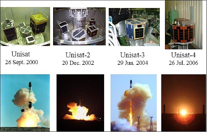
UniSat (University Satellite)
UniSat (University Satellite) Program
UniSat is an experimental microsatellite program of the University of Rome (Universita di Roma “La Sapienza”, Scuola di Ingegneria Aerospaziale). Education and hands-on experience of students and faculty in the field of aerospace engineering is the overall theme of the program (involving a number of Italian universities), funded by the Italian Government MURST (Ministry of University and Technological Research) and by ASI (Italian Space Agency). In the framework of the UniSat program, a laboratory for satellite design and construction and an amateur ground station called SPIV (San Pietro in Vincoli), were established at the University of Rome. 1) 2) 3)
Spacecraft
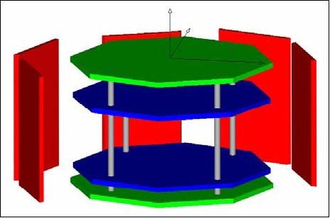
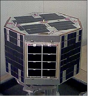
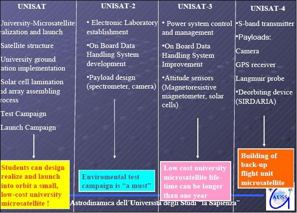
The UniSat-1 development phase started in 1997 at GAUSS (Gruppo di Astrodinamica dell' Universita degli Studi “la Sapienza”), sponsored by ASI in cooperation with other Government Research Centers and with industry. The S/C body structure consists of an octagonal prism, 40 cm in diameter and a height of 25 cm. The modular tray design employs five Al/Al honeycomb plates, kept together by four stainless steel bars. Eight lateral panels with surface-mounted solar panels make up the external surface of the spacecraft. The satellite is spin-stabilized at 5 rpm with the spin-axis normal to the orbital plane. Attitude is sensed with two three-axis magnetometers and the use solar panels as a sun-sensing system. Actuation is provided by an active magnetic control system for spin-axis orientation and for spin rate control. One equatorial coil is used for spin-axis orientation and two transverse magnetic coils are used for spin-up/spin-down maneuvers. An average power of 10 W is provided by the solar panels. In addition, NiMH batteries of 2.4 Ah capacity are used for eclipse operations. The OBC (On-Board Computer) consists of a distributed network of microcontrollers (master/slave architecture) providing flexibility and reliability. UniSat-1 has a mass of 12 kg, qualifying almost as a nanosatellite. The S/C design life is one year.
The RF communications are implemented according to AMSAT standards with VHF (145.848 MHz) in uplink and UHF (436.450 MHz) in the downlink using the AX.25 packet protocol at data rates of 9.6 kbit/s. The UHF transmitting antenna consists of four dipoles providing circular polarization. The VHF receiving antenna is a dipole.
Launch
A launch of UniSat-1 took place on Sept. 26, 2000 from the Baikonur Cosmodrome on a Dnepr launch vehicle of ISC Kosmotras. UniSat-1, along with MegSat of Italy and TiungSat 1 of Malaysia, and SaudiSat-1A and -1B of SISR (Saudi Institute for Space Research), was launched in a multiple launch configuration (no primary payload). UniSat-1 is being operated by students.
Orbit: Circular orbit, altitude = 650 km, inclination = 65º, period = 98 minutes.
Mission Status
UniSat-1 is no more operational.
Sensor Complements
The power subsystem represents two experiments; one involves a solar panel environment test, the second experiment involves a functional NiMH (Nickel Metal Hydride) battery test. The new batteries offer a much better capacity/mass ratio than conventional NiCd batteries. The OBC distributed network architecture is a proof-of-concept test.
UniSat-2 (University Satellite-2)
UniSat-2 is a follow-up microsatellite project of the University of Rome (Universita di Roma “La Sapienza”, Scuola di Ingegneria Aerospaziale). The overall objective of this mission is to develop, and demonstrate an onboard micro-propulsion system, followed by a performance assessment. Such a system might eventually be used for future precise attitude control of a nanosatellite. 5)
Spacecraft
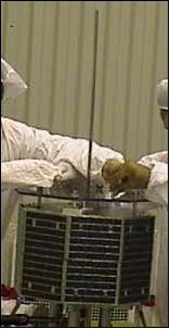
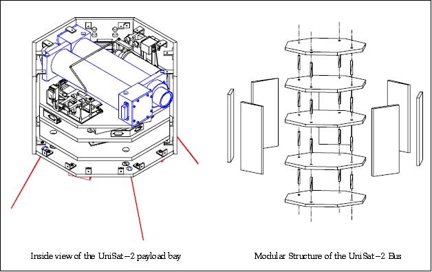
UniSat-2, built by the GAUSS Laboratory of the University of Rome, is a spin stabilized spacecraft with the same dimensions as those of UniSat-1 consisting of an octagonal prism of 150 mm side length and 250 mm in height. The S/C has a modular structure made of five Al/Al honeycomb plates, kept together by four aluminum bars. Eight Al/Al honeycomb lateral panels, with surface-mounted solar panels, complete the satellite cylinder structure.
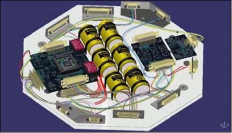
The S/C architecture consists of a multipurpose bus, able to accommodate several kinds of payloads (a tray system), and to accommodate change. The overall design permits easy assembling and disassembling, where each plate is devoted to a subsystem, thus allowing separate testing just before final integration. A Li-ion battery is used for ecliptic-phase operations, the S/C mass is 12 kg.
Launch
A launch of UniSat-2 from the Baikonur Cosmodrome on a Dnepr-1 vehicle took place on Dec. 20, 2002.
The co-passenger payloads on this multiple S/C flight were:
• LatinSat-1/2 (each of 12 kg) communications satellites for Aprize Satellite of Argentina. The objectives are monitor both fixed and mobile goods for the transportation industry.
• Rubin-2 (10 kg) a communications satellite of OHB-System, Germany. Rubin-2 uses the ORBComm network comprising 30 satellites to ensure interruption-free communications with the Earth.
• SaudiSat-2 (15 kg) scientific satellite for the Riyadh Space Research Institute, Saudi Arabia
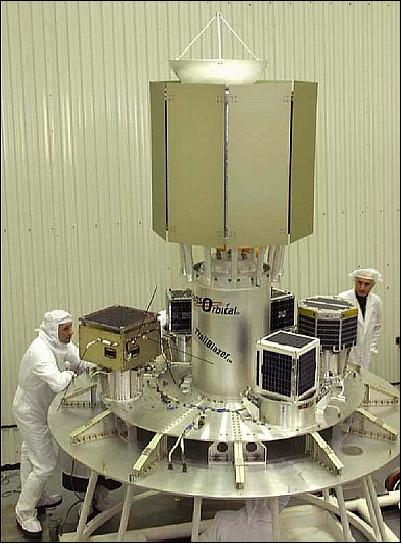
• Trailblazer (110 kg) a technology minisatellite and a mockup of a future commercial lunar orbiter of TransOrbital, La Jolla, CA, USA.
Orbit: Circular orbit, altitude = 650 km, inclination = 65º, period = 97.8 minutes.
RF communications are in the amateur (AMSAT) UHF/VHF bands at 9.6 kbit/s using the AX.25 packet protocol. The UHF transmitting antenna consists of four dipoles providing circular polarization. The VHF receiving antenna is a dipole. The satellite is being operated by the University of Rome.
Mission status: UniSat-2 is no more operational.
Sensor Complement
AMI (Aerosol Monitoring Instrument)
AMI consists of two wide-angle CCD cameras. One of the cameras is equipped with an INSpector for digital spectroscopy in the spectral range of 430-900 nm. This information is used for precise mapping of the aerosols on Earth surface.
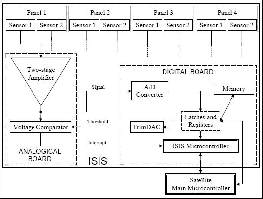
ISIS (In Situ Impact Sensor)
The debris impact sensors are made of piezoelectric devices (analog and digital boards hosting a dedicated microcontroller) used to register the impacts of sub-millimeter particles to obtain statistical information about the LEO environment. 6)
The piezoelectric elements can measure acoustic waves propagating through the satellite structure after an impact of sufficient momentum. Moreover, other effects might be measured in case of direct impacts on the sensors surface (for instance, some piezoelectric materials also show a pyroelectric behavior).
CGM (Cold-Gas Microthruster)
The experimental CGM was jointly developed by Mechatronic System Technik GmbH, Villach, Austria, and by INFM-TASC at Elettra Synchrotron Light Source, Trieste, Italy. The main CGM elements are: control valves and nozzles, pressurized N2 tank, control board, safety valve group, connections, and aluminum plates. The microthruster employs a chamber in which the pressurized nitrogen gas is introduced terminating in a supersonic nozzle in which the gas is accelerated. The throat dimension (0.02 mm diameter) defines the thrust range and is controlled by means of a proportional valve and a pressure sensor. A variable thrust of up to 560 µN is generated. CGM has a total mass of 0.835 kg.
The in-orbit experiment onboard UniSat-2 consists of successive spin-up/spin-down maneuvers using the microthrusters. The satellite nominal spin rate is 3 rpm, with the spin axis aligned to the orbit normal. The gas stored in the tank is enough to perform a sequence of six spin-up/ spin-down maneuvers. One spin-up and one spin-down maneuver per orbit are performed. The time duration of the whole experiment is limited by the microvalve leakage, imposing the experiment to be completed within one day from the safe valve actuation.
The final goal of the CGM project is further miniaturization of the system and the enhancement of its performance for eventual use in a nanosatellite ACS (Attitude Control Subsystem). Such an ACS requires a maximum thrust of about 100 µN that may be achieved using a Hydrazine propellant with an estimated mass flow rate of 0,1 mg/s and a reaction chamber pressure of about 0.3 MPa. A continuous modulation of the thrust is also required; this may be achieved in a control scheme where the pressure in the reaction chamber is used as a feedback signal for controlling the valve opening and thus the mass flow rate. 7) 8)
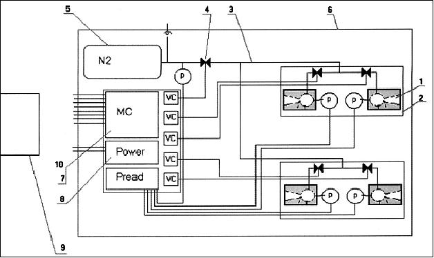
Legend to Figure 7: 1) microthruster; 2) thrusters group; 3) fluidics connections; 4) safety valve; 5) gas tank; 6) mechanical interface; 7) control unit; 8) power; 9) UniSat-2; and 10) Control Software.
UniSat-3
UniSat-3 is the third microsatellite of the University of Rome “La Sapienza”, built by a team of students, researchers and professors at the GAUSS Laboratory.
Spacecraft
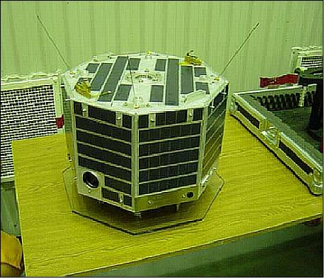
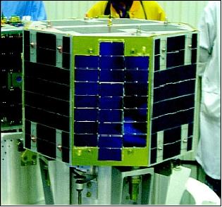
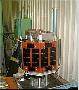
UniSat-3 is based on the design of the previous two satellites. The spacecraft body is an octagonal prism in shape, 40 cm in diameter and a height of 25 cm. Four aluminium sandwich trays are assembled and kept together by four aluminium columns. Each tray contains a subsystem, allowing for separate manufacturing and testing activities. The trays are octagonal plates of 150 mm side with an overall height of 250 mm for the satellite. The columns are aluminium threaded rods, 6 mm in diameter, encompassing the structure. Eight aluminum panels provide the outer enclosure of the satellite. The solar arrays are surface-mounted on the outside of these panels. 9) 10) 11)
The spacecraft is stabilized using passive magnetic attitude control (no orbit control capability). The system employs a permanent magnet and an energy dissipation system, consists of three magnetic hysteresis rods. The satellite is not equipped with dedicated attitude sensors, except for a COTS three-axes magnetoresistive magnetometer (TAM). Attitude determination (in the order of about 10º) is performed using magnetometer readings and the telemetry data of three solar panels.
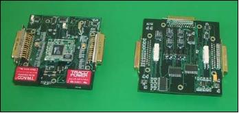
An average power of 12.3 W is provided by silicon solar arrays (16% efficiency), an NiCd battery (4 Ah capacity) is used for eclipse operations. The electronic components consist of several boards. The C&DH (Command and Data Handling) subsystem is a compact module, RCM3400, that incorporates a Rabbit 3000 8-bit microprocessor, operating at 29.4 MHz, an 11 bit 8 channel (or 12 bit 4 channel if used in differential mode) A/D converter, 512 kbyte of flash memory, 512 kbyte of static RAM and two clocks (main oscillator and time-keeping). The spacecraft mass is 12 kg.
RF communications: The S/C communications conform to amateur radio standards permitting a data rate of 9.6 kbit/s full duplex communications. The uplink is in VHF (145 MHz), the downlink in UHF (436 MHz). The communications protocol used is the HDLC (High-level Data Link Control). Each piece of raw data is encapsulated by the microprocessor in an HDLC frame by adding a trailer and a header.
Launch
A launch of UniSat-3 took place on June 29, 2004, on a Dnepr launch vehicle from the Baikonur Cosmodrome, Kazakhstan.
UniSat-3 was part of a multiple payload launch consisting of the following additional satellites: SaudiComsat-1, SaudiComsat-2 and SaudiSat-2 from Saudi Arabia (KACST); AprizeSat-1 (LatinSat-C), AprizeSat-2 (LatinSat-D), and AMSAT OE (Echo) from USA (SpaceQuest); DEMETER from France (CNES), AKS-1 from Russia (Aerospace Systems), and Celestis-04, a space burial from USA (CPAC).
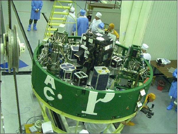
Orbit: Sun-synchronous orbit, mean altitude = 750 km, inclination = 98º. Local equator crossing time on ascending node at 22:30 hours.
Mission Status
UniSat-3 is operational in 2010 (more than 5 1/2 years after launch). The data of the spacecraft are being received at the University of Rome ground station on a regularly basis.
• The magnetometer experienced a z-axis failure during the first year in orbit. 12)
Sensor Complement
All the electronic boards and photovoltaic system can be considered as payloads, as they are realized with commercial electronic components, not qualified for space environment. 13) 14)
Solar Cell Experiment (Power Subsystem)
Four experimental solar panels are installed on the lateral surfaces in order to test different solutions. Several bonding techniques were employed.
• Terrestrial grade monocrystalline silicon solar cells (BP-Saturn7), encapsulated using an improved terrestrial technology procedure, are the basis of the photovoltaic system.
• One panel was made by Kiev Polytechnic Institute of the National Technical University of Ukraine. This panel was manufactured with monocrystalline silicon solar cells, covered with glass. The nominal efficiency is about 15%. The cells are bonded to an aluminum honeycomb panel using polyimide film as dielectric insulation.
• Three panels were manufactured using triple junction GaAs cells with different cover materials to test in-orbit degradation. The nominal efficiency of the triple junction solar cells is 21%. Each array is realized by two parallel arrays. Each string has a series of four solar cells (Figure 15).
The power subsystem features a newly developed MPPT (Maximum Peak Power Tracking) device; the objective is to track the solar panels in such a fashion to obtain the maximum power operative condition, adapting to changing illumination and S/C temperature. The MPPT is based on a step-up DC/DC converter, in which the battery voltage is higher than the solar array voltage. The solar array connected to the MPPT is made of 14 silicon solar cells, with 7.6 V nominal open circuit voltage.
Magnetometer (Honeywell HM2003) for the measurement of the Earth's magnetic field (strength and direction). The 3-axis device is mounted on a PCB (Printed Circuit Board) containing the management circuitry.
MPPT (Maximum Peak Power Tracking)
The prototype MPPT system has been designed, manufactured and tested to be demonstrated on the satellite. The objective of MPPT was to improve the performance of the onboard power generation system. The MPPT includes an adjustable DC/DC converter connecting the solar panel to the load. In this way the system is capable to track autonomously the solar array maximum power operative condition, adapting to changing illumination and temperature events during the orbital phases. The MPPT configuration implemented is considered an upgrade configuration to conventional systems, in which the voltage of the battery is higher than the voltage of the solar arrays.
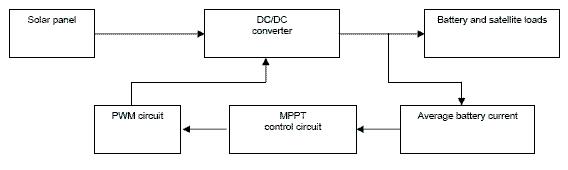
The MPPT has been manufactured on a PCB (Printed Circuit Board) consisting of six layers. SMD (Surface Mount Device) components have been exploited to reduce the volume (50 mm x 82,4 mm) and the mass of the circuitry to ~ 50 g. All other electronics of the system are COTS (Commercial-of-the-Shelf) components. 15)
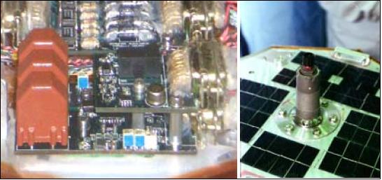
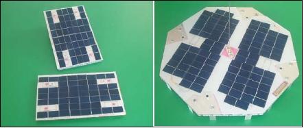
Figure 17: Solar panel of UniSat-3 constructed for MPPT test (left) and MPPT board (right), image credit: GAUSS)
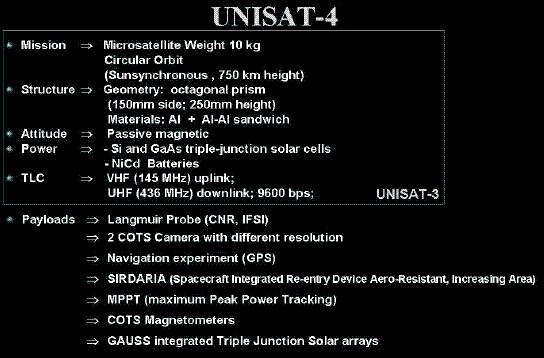
UniSat-4
UniSat-4 is the fourth microsatellite of the University of Rome ”La Sapienza”, built by a team of students, researchers and professors at the GAUSS laboratory.
Spacecraft
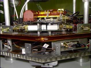
UniSat-4 is based on the design of the previous UniSat satellites. Four aluminum sandwich “trays” are assembled and kept together by four aluminum columns. Each tray is devoted to a particular subsystem, allowing for separate manufacturing and testing activities. The trays are octagonal plates of 150 mm side with an overall height of 250 mm for the satellite.
The C&DH subsystem is an embedded microprocessor system module, the RCM3400, including a Rabbit 3000 8-bit microprocessor, operating at 29.4 MHz, an 11-bit 8-channel (or 12-bit 4-channel if used in differential mode) A/D converter, 512 kB of flash memory, 512 kM of static RAM and two clocks (main oscillator and time-keeping).
The power subsystem is based on a photovoltaic system and Ni-Cd batteries. The solar arrays are directly connected to the battery, through a blocking diode. In this configuration, the solar array voltage must be higher than the battery voltage. The solar panels are manufactured using monocrystalline silicon panels, based on the same technology successfully used in previous UniSat missions, and triple junction solar cells. The silicon cells have an efficiency of about 15%, while triple junction cells have an efficiency of about 24%.
The batteries are 4Ah NiCd cells. This choice is mainly due to the reliability and long experience of in orbit performance of this batteries technology.
The differences between UniSat-3 and UniSat-4 are outlined in Figure 19. The UniSat-3 and UniSat-4 bus are the same: However, UniSat-4 offers a number of different payloads. 16)
Launch
The launch of UniSat-4 (10 kg mass) took place on July 26, 2006, on a Dnepr launch vehicle from the Baikonur Cosmodrome, Kazakhstan. UniSat-4 was part of a multiple payload launch.
• The following co-passenger CubeSats were flown: ION (Illinois Observing Nanosatellite ) of the University of Illinois at Urbana¿Champaign; Sacred (Study of the Action of Cumulative Radiation on Electronic Devices) of the (University of Arizona; KUTESat (Kansas Universities' Technology Evaluation Satellite) of the University of Kansas, Lawrence, KS; ICEcube-1, -2 (Ionospheric Scintillation Experiment) of Cornell University), Ithaca, NY; RinconSat of the University of Arizona, Tucson, AZ; SEEDS (Space Engineering Educational Satellite) of Nihon University, Tokyo, Japan; HAUSat-1 (Hankuk Aviation University Satellite-1) of Hankuk Aviation University, Seoul, South Korea; nCube-1 (Norsk Romsenter), Norway, MEROPE (Montana Earth-Orbiting Pico-Explorer) of Montana State University, Bozeman, MT; AeroCube-1 of The Aerospace Corporation, El Segundo, CA; PolySat-1, -2 of CalPoly, San Luis Obispo, CA; and Voyager of the University of of Hawaii. The 14 CubeSats from 10 different universities and 1 company participated in the CubeSat launch, coordinated by California Polytechnic State University (CalPoly).
• Additional smallsats on the flight were: Belka (RKK Energia) the first remote sensing satellite of Belarus with 250 kg, Baumanets (NPO Mash) with 80 kg, and PicPot (University of Torino) with 3 kg.
Mission Status
• UniSat-4 is not active due to a launch failure which occurred after 2 minutes of flight.
This launch failure represented a great setback and disappointment to all institutions involved. An investigation disclosed that the launch failure was due to a malfunctioning hydraulic drive unit in a combustion chamber on the booster's first stage.
Orbit: Sun-synchronous orbit, mean altitude = 750 km, inclination = 98º.
Technology Experiments
MPPT (Maximum Peak Power Tracking)
MPPT has been designed, manufactured and tested to be boarded on the satellite. This is a system capable to track the solar array maximum power operative condition, adapting to changing illumination and temperature (see description under UniSat-3).
COTS (Commercial-off-the Shelf) Cameras
The UniSat-4 microsatellite hosts two CCD-based programmable cameras. The CCD sensor contains 640 x 480 pixels. The JPEG compression algorithm is used with the compression factor selectable by ground command. The two cameras have different optics and resolution. In this way, UniSat-4 is able to take pictures of the Earth's surface in the northern hemisphere.
One camera is provided with optics of 2.5 mm focal length, providing a FOV (Field of View) of 84.6º and a resolution of about 0.8 km/pixel. The second camera is equipped with optics of 6 mm focal length (36.8º FOV) providing a 0.3 km/pixel resolution. The FOVs of the two cameras are overlapping to take imagery of the same target area with different resolutions.
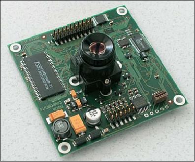
The camera software is written in such a way as to select snapshots by lighting condition criteria. The shutter is regulated automatically. Only pictures with the required luminosity are stored in the onboard memory. The camera responds to different commands involving the time schedule as well as the amount of images to be taken. The sun sensor uses optics with a focal length of 2.5 mm for maximum FOV applications.
GPS Receiver
This is a complete GPS OEM sensor implementation. The autonomous 12-channel receiver is capable of tracking automatically all GPS satellites in view providing a 3D position and velocity solution with an associated figure-of-merit. In addition, the GPS receiver features an SBAS (Satellite Based Augmentation System) option for WAAS and EGNOS service support. The formats supported are binary and NMEA-0183 (National Marine Electronics Association) standard.
The receiver power supply voltage is 3.3 VDC, and the current is about 0.15 A, leading to a power consumption of about 0.5 W. The device dimensions are 41 mm x 71 mm x 13 mm, the mass is about 22 g, representing only a minor impact on the satellite's mass budget.
With a sampling rate of 1/60 Hz (data rate is up to 1 Hz), it is possible to obtain about 100 GPS data measurements in one orbit, sufficient for an accurate position determination. Moreover, the GPS time signal will be used to set the onboard real-time clock, which is important to synchronize on-orbit position with the telemetry data.
Different data types may be requested from the GPS receiver, such as navigation data [time, position, velocity, HDOP (Horizontal Dilution of Position), GDOP (Geometric Dilution of Position). etc.]. The GPS data are being used in two different experiments. The first one involves the Langmuir probe and the GPS navigation data, which are used to define the exact position of probe samplings. In the second experiment, data are being collected of in-view GPS satellites along with magnetometer, sun sensor, and solar panels data to determine the attitude of the satellite.
Magnetometers
Three magnetometers, based on different technologies, are hosted onboard UniSat-4. Two magnetometers use the magneto resistive device of Honeywell HMC 2003. One of these provides digital outputs; the other one, re-designed and tested at the University of Rome laboratory, provides analog outputs. 17) 18)
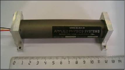
The third magnetometer, by Applied Physics Systems, is a fluxgate sensor providing digital outputs. The main goal of hosting three types of magnetometers is to compare their performances in orbit. The magnetic field measurements are also being used onboard for active magnetic attitude control, and on the ground for attitude determination.
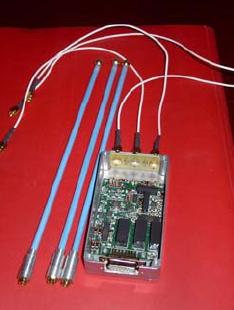
S-band Transmitter
The UniSat bus communication system uses a 9600 bit/s digital communication channel in the UHF/VHF bands. In addition, an S-band transmitter (2.4 GHz) is installed onboard UniSat-4 to improve the data rate, as required by the considerable amount of data generated by the sensor complement. The downlink data rates available (24, 48, or 96 kbit/s) are selectable by ground station command. A dedicated flash memory of 4 MByte is being used for onboard data storage.
SIRDARIA (Spacecraft Integrated Reentry Device Aero Resistant Increasing Area)
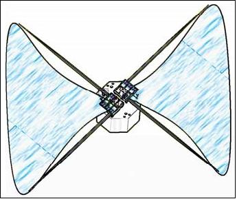
SIRDARIA is an innovative passive deorbiting mechanism designed and developed at GAUSS. The overall objective is to provide a means for spacecraft deorbiting at the end of its operational life within a suitable time period. The principle of SIRDARIA is based on a cross-sectional drag increase of the spacecraft by unfolding a triangular sail on two deployed booms. UniSat-4 will carry two butterfly sails for a symmetrical configuration. 19)
Numerical simulations using DAS (Debris Assesssment Software) have been carried out to evaluate the efficiency of the SIRDARIA system. A total sail surface area of 1.2 m2 is being used with respect to the UniSat-4 main surface of 0.09 m2 considering different orbital altitudes for analysis. All parts of SIRDARIA are realized in aluminum. The main body of the system supports booms, hosts the opening system, the connectors for power connection and the folded sail; moreover it contains the interface with the satellite.
TPS (Triple Probe System)
TPS is a prototype electrostatic probe to infer local plasma density and electron temperature determination through the acquisition of instantaneous voltage and current measurements. The objective of TPS is to study ionospheric plasma parameter variations which might be related to forthcoming earthquake analysis. 20)
During the pre-seismic process activity in the hypocentral zone of an earthquake, the micro-fracture of the rock arises, linked to variations of stress in the lithosphere (i.e., the outer layer of the Earth's crust with a thickness of about 100 km). The electromagnetic signals emitted from stressed rocks in the ELF-ULF bands (0-3000 Hz) seem to be the cause of irregularities in the ionospheric plasma parameters that can be measured by satellites several hours (0-24 h) prior to the main phase of an earthquake.
The TPS consists of three electrodes exposed to the plasma and driven by an electronic circuit. Each of the electrodes has a spherical shape to provide its results independently of the satellite's attitude. The instrument mass and volume are extremely reduced to make it compatible with microsatellite constraints.
To avoid electrical interference among the electrodes, the relative distances should be much larger than the shielding distance λD (Debye length), which, in typical ionospheric conditions, ranges from 0.2 to 1 cm. In this experiment the distance among the probes has been fixed at 10 cm.
The electrodes are fixed to rods, realized with dielectric material (resin-glass), which separate them from the spacecraft assuring also the stiffness required to withstand the launch and space environment loads. The rods are 25 cm long to avoid interferences caused by electrical charging of the spacecraft.
References
1) F. Graziani, M. Ferrante, G. B. Palmerini, F. Santoni, P. Tortora, “UniSat program: a University Tool for Space Education,” Proceedings of the 51st IAF Congress, Rio de Janeiro, Brazil, Oct. 2-6, 2000, IAF-00-P.2.07
2) F. Graziani, G. B. Palmerini, F. Santoni, P. Tortora, C. Marchiori, “Mechanical Design and Manufacturing of the Microsatellite UniSat,” ESA Special Publication, SP-468, 2001, Conference proceedings of “Spacecraft Structures, Materials & Mechanical Testing,” Nov. 1-12, 2000, Noordwijk
3) Filippo Graziani, Fabrizio Piergentili, Fabio Santoni, “A space standards proposal for university-class Microsatellites,” Proceedings of the 59th IAC (International Astronautical Congress), Glasgow, Scotland, UK, Sept. 29 to Oct. 3, 2008, IAC-08.D1.5.7
4) C. Cappelletti, F. Paolillo, F. Guarducci, L. Ridolfi, F. Graziani, P. Teofilatto, F. Santoni, F. Piergentili, M. L. Batagliere, “From UNISAT to UNICubeSAT,” 5th Annual CubeSat Developers' Workshop, San Luis Obispo, CA, USA, April 9-11, 2008, URL: https://web.archive.org/web/20150612073601/http://mstl.atl.calpoly.edu/~bklofas/Presentations/DevelopersWorkshop2008/session6/6-UNICubeSAT-Chantal_Capelletti.pdf
5) F. Santoni, P. Tortora, F. Graziani, G. Manzoni, E. Di Fabrizio, L .Vaccari, “Micropropulsion Experiment on UniSat-2,” Proceedings of IEEE Aerospace Conference, Big Sky, MT, March 9-16, 2002
6) F. Graziani, M. Porfilio, F. Santoni, “An In Situ Impact Sensor on board a UniSat microsatellite for monitoring the microparticles environment,” Proceedings of the 6th Cranfield DCSSS Conference, July 18-22, 2004, Riomaggiore, Italy. URL: http://naca.central.cranfield.ac.uk/dcsss/2004/C22_articolo_ISIS_5_Terre_2004EDITfinal.pdf
7) L. Vaccari, M. Altissimo, E. Di Fabrizio, F. De Grandis, G. Manzoni, A. Gerardino, F. Perennes, P. Miotti, “Design and prototyping of a micropropulsion system for microsatellites attitude control and orbit correction,” Journal of Vacuum Science and Technology, B, Vol. 20, No 6, Nov./Dec. 2002, pp. 2793-2797
8) F. Santoni, P. Tortora, F. Graziani, G. Manzoni, E. De Fabrizio, L. Vaccari, “Micropropulsion experiment on UniSat-2,” Proceedings of the IEEE Aerospace Conference 2002, Big Sky, MT, USA, March 9-16, 2002
9) F. Graziani, F. Santoni, F. Piergentili, F. Bulgarelli, M. Sgubini, S. Bernardini, “Manufacturing and launching student-made microsatellites: “hands-on” education at the University of Roma,” Proceedings of IAC, 2004, Vancouver, Canada, Oct. 4-8, 2004, IAC-04-P.5.A.02
10) F. Graziani, F. Santoni, F. Piergentili, F. Bulgarelli, M. Sgubini, “UniSat-3 Mission: Preliminary Results,” Aerotecnica Missili e Spazio Vol. 83, No 4, 2004, pp. 175-184
11) F. Santoni, F. Piergentili, “UniSat-3 Attitude Determination using Solar Panel and Magnetometer Data,” Proceedings of the 56th IAC 2005, Fukuoda, Japan, Oct. 17-21, 2005, IAC-05-C1.2.06
12) F. Graziani, F. Santoni, F. Piergentili, F. Bulgarelli, M. Ronzitti, M. Sgubini, “UniSat-3 results after one year operations in orbit,” Workshop on University Microsatellites in Italy, University of Rome, July 27, 2005
13) F. Santoni, F. Piergentili, F. Graziani, “In orbit performances of the UniSat-3 solar arrays,” Proceedings of the 57th IAC/IAF/IAA (International Astronautical Congress), Valencia, Spain, Oct. 2-6, 2006, IAC-06-C3.4.-D3.4.04
14) F. Graziani, 2nd International Workshop ”Spaceflight Dynamics and Control” University of Beira Interior, Covilha, Portugal, Oct. 9-11, 2006, URL: http://www.aerospace.ubi.pt/.../portogallo_Filippo_Graziani.pdf
15) F. Santoni, F. Piergentili, “Design and test of a Maximum Power Point Tracking System for UniSat-3 Microsatellite,” Proceedings of the 55th International Astronautical Congress, Vancouver, Canada, Oct.. , 2004, IAC-04-R.2. 01
16) F. Santoni, F. Piergentili, F. Bulgarelli, F. Graziani, “The UniSat Program: Lessons Learned and Achieved Results,” Proceedings of the 57th IAC/IAF/IAA (International Astronautical Congress), Valencia, Spain, Oct. 2-6, 2006, IAC-06-E1.1.10,
the same topic is also in: Acta Astronautica, Volume 65, Issues 1-2, July-August 2009, pp. 54-60
17) F. Santoni, M. Zelli, “Passive Magnetic Attitude Stabilization of the UniSat-4 Microsatellite,”Proceedings of the 57th IAC/IAF/IAA (International Astronautical Congress), Valencia, Spain, Oct. 2-6, 2006, IAC-06-C1.1.05
18) ,F. Graziani, F. Santoni, F. Piergentili, M. Agostinelli, M. L. Battagliere, F. Bulgarelli, M. Ronzitti, M. Sgubini, “Fundamental Physics in Space with Small Payloads (FPS-06),” Frascati, Italy, March 21-23, 2006
19) F. Piergentili, F. Graziani, “SIRDARIA: A low-cost autonomous deorbiting system for microsatellites,” Proceedings of the 57th IAC/IAF/IAA (International Astronautical Congress), Valencia, Spain, Oct. 2-6, 2006, IAC-06-B6.4.07
20) M. L. Battagliere, F. Piergentili, G. Vannaroni, F. Graziani, “Triple Probe System For In Situ Ionospheric Plasma Monitoring,” XVIII Congresso Nazionale A.I.D.A.A., Volterra (PI), Italy, Sept. 19-22, 2005
The information compiled and edited in this article was provided by Herbert J. Kramer from his documentation of: ”Observation of the Earth and Its Environment: Survey of Missions and Sensors” (Springer Verlag) as well as many other sources after the publication of the 4th edition in 2002. - Comments and corrections to this article are always welcome for further updates.(eoportal@symbios.space)