BIROS (Bi-spectral InfraRed Optical System)
EO
Mission complete
DLR
The Bi-spectral Infrared Optical System (BIROS) was one of two spacecraft in the German Aerospace Center (DLR)’s FireBird constellation, with the other being the Technology Experiment Carrier-1 (TET-1). The primary goal of the BIROS mission was to facilitate the detection and subsequent monitoring of High Temperature Events (HTEs), e.g. forest fires, using an optical IR payload. Launched in June 2016, BIROS served emergency response agencies internationally until its end of life in December 2020.
Quick facts
Overview
| Mission type | EO |
| Agency | DLR |
| Mission status | Mission complete |
| Launch date | 22 Jun 2016 |
| End of life date | 31 Dec 2020 |
| CEOS EO Handbook | See BIROS (Bi-spectral InfraRed Optical System) summary |
Summary
Mission Capabilities
The main instrumentation was the BIROS optical payload, comprising three pushbroom cameras. BIROS utilised infrared spectroscopy to detect HTEs such as wildfires and volcanic eruptions, initially quantifying the scale and danger of such events.
BIROS also employed sophisticated onboard processing, including georeferencing using on-board navigation and hotspot deception using the BIRD (Bi-spectral InfraRed) algorithm. This allowed for a far faster identification of HTEs and direct-to-user ground transmission, greatly improving response times to such events.
Performance Specifications
One pushbroom camera operated in the near-infrared (VNIR) spectral range, while the other two were infrared pureplays. A field of view (FOV) of 19.6º contributed to a sample width of 42.4 m and a swath width of 211 km. The secondary instrument, OSIRIS, was designed particularly with Size, Weight and Power (SWaP) considerations in mind, weighing approximately 5 kg and drawing a maximum power of 50 W.
BIROS orbited in a sun-synchronous orbit, maintaining an altitude of 515 km and inclination of 97.56º.
Space and Hardware Components
The spacecraft architecture was from the TET-X platform, with slight improvements over the already operating TET-1 satellite bus. Innovations included a new power subsystem, new transmitters and a largely improved OnBoard Computer (OBC) in order to support the greater demands of onboard processing. BIROS utilised RF communications, transmitting in the S-band with 4 kbit/s uplink data rate and two cold redundant transmitters with a downlink high bit rate of 6 Mbit/s. An experimental very high frequency (VHF) modem was also installed to facilitate communication with an ORBCOMM relay satellite, allowing for direct space-to-ground hotspots alerts.
One secondary objective was the testing of OSIRIS, a new onboard optical communication terminal, demonstrating laser communication in space up to 1 Gbit/s of data transfer speeds and a four-quadrant laser detector, improving pointing accuracy. Another secondary goal was the trialling of AVANTI, an Autonomous Vision Approach Navigation and Target Identification system. The architecture demonstrated the ability to rendezvous with non-cooperative satellites using vision-based navigation.
BIROS (Bi-spectral InfraRed Optical System)
Spacecraft Launch Mission Status Sensor Complement Ground Segment References
Overview
BIROS is a follow-on fire detection mission of DLR based on TET-1 (Technology Experiment Carrier-1). The BIROS satellite is part of DLR's FireBird constellation, which consists of two spacecraft, TET-1 and BIROS. The primary goal of this mission is the detection and monitoring of so called HTEs (High Temperature Events), e.g. forest fires or other hot spots.
The secondary BIROS mission goals are:
• The processing capabilities of the BIROS payload will be considerably upgraded.
• BIROS will be equipped with OSIRIS (Optical Space Infrared Downlink System), a new onboard optical communication terminal, developed at DLR, to demonstrate the following capabilities:
- three different laser systems for downlink communications at data rates up to 1 Gbit/s
- four quadrant laser detector onboard for improved pointing accuracy
- a beacon laser in uplink to support the BIROS attitude control; it may also be used for an optical uplink.
• VAMOS (Verification of Autonomous Mission Planning On-board a Spacecraft). VAMOS is a DLR/GSOC software experiment with the objective to schedule and (re-)command tasks. 1) 2)
• AVANTI (Autonomous Vision Approach Navigation and Target Identification), an optical navigation experiment. The goal is to demonstrate autonomous rendezvous to (and departure from) a non-cooperative client using vision-based navigation. 3)
• BIROS will carry onboard the picosatellite BEESAT-4 (Berlin Experimental and Educational Satellite-4) of TU Berlin(1U CubeSat, 1 kg) and release it through a spring mechanism [ejection by SPL (Single Picosatellite Launcher ) after the successful check-out and commissioning of all relevant BIROS subsystems]. After separation, it will perform experimental proximity maneuvers in formation with the picosatellite solely based on optical navigation. 4)
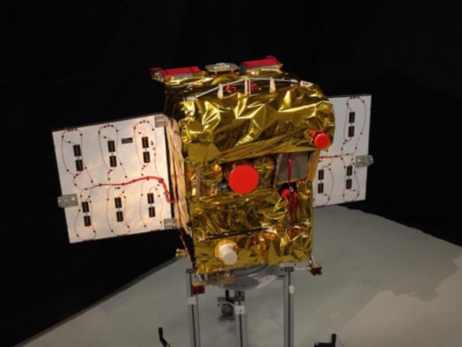
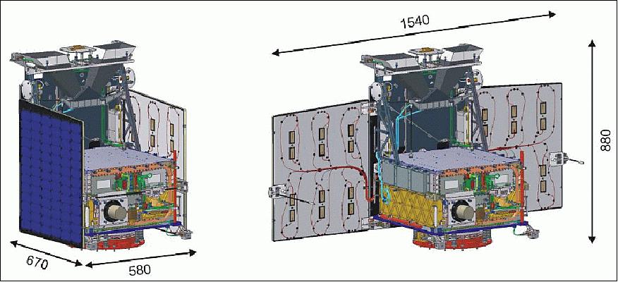
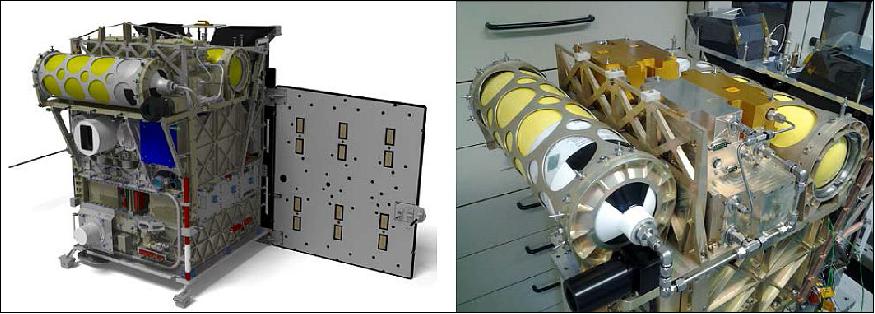
Spacecraft
For BIROS, the TET-X platform is being used, a slightly improved version of the existing TET-1 satellite bus. The TET-X bus shares the TET-1 bus envelope of 670 x 580 x 880 mm3 and 70 kg satellite bus mass with 460 x 460 x 428 mm3 payload volume and 50 kg payload mass. The three-axis attitude control system provides a pointing knowledge of 10 arcsec and a position accuracy of 10 m. But the TET-X bus contains a new power subsystem, new transmitters and OBC (OnBoard Computer), with same envelopes and masses as for TET-1.
The BIROS spacecraft will be built again in a cooperation of DLR and AFW (Astro Feinwerktechnik GmbH), Berlin Adlershof. Both satellites (TET-1 and BIROS) are equipped with an identical main payload. These are the infrared cameras for Earth observation, especially hot spot detection. As part of the DLR FireBIRD mission, both satellites shall be used in a constellation for fire detection and monitoring. 5) 6) 7) 8) 9) 10) 11)
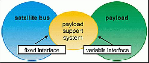
A special point in the design of the satellite bus was the interface between satellite bus and payload. To support different kinds of missions, the system contains the nominal satellite bus and a PSS (Payload Supply System). This payload supply system is on its payload interface side adaptable to the data (SpaceWire, RS422/485, CAN-Bus, etc.) and power interface requirements, data storage requirements and payload control requirements.
The nominal satellite bus will remain unchanged for different missions, but of course can be adapted in parts, like an upgrade to X-band system if higher data rates are required. The PCBs (Printed Circuit Boards) of the PSS will be adapted for every new payload accommodation.
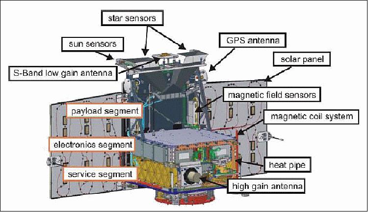
TET-X bus (as well as the TET-1 bus): The TET bus is comprised of three segments: the Service Segment, the Electronic Segment and the Payload Segment (Figure 3).
Bus electronics: All electronic parts of the Electronic Segment are designed as PCBs in Europe Card size (160 x 100 mm2). A total of 15 PCBs for the PSS (max) electronics and 15 PCBs for the satellite bus (max) electronics can be integrated in the Electronics Segment of TET. All PCBs of the segment are connected via two backplanes.
Payload platform: The payload segment contains the payload(s) itself, parts of the AOCS (Attitude and Orientation Control System) and one of the low gain antennas. The TET payload platform is the sole mechanical and thermal interface between the payload(s) and satellite bus. The TET payload platform allows an easy and fast integration of the pre-assembled payload(s). Although in the TET-1 mission it was not required, the TET payload platform can be also designed as an optical bench.
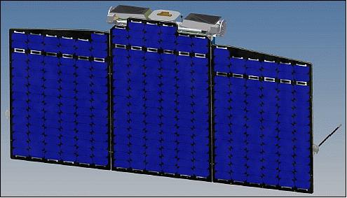
EPS (Electrical Power Subsystem): The EPS consists of a PCDU (Power Control & Distribution Unit), two battery stacks and a solar generator comprising 3 panels (1 fixed and 2 deployable) with 280 W EOL electrical power capacity. A Li-ion, 520 Wh, battery is providing the energy in the eclipse phase or during peak power demands.
OBC (OnBoard Computer): The OBC features a multiple redundant design and controls all activities of the satellite bus. The system layout contains 4 redundant computers and watchdog circuits for failure detection and recovery. One node (the "worker") is controlling the satellite while the second (the "master" node) is supervising the correct operation of the worker node.
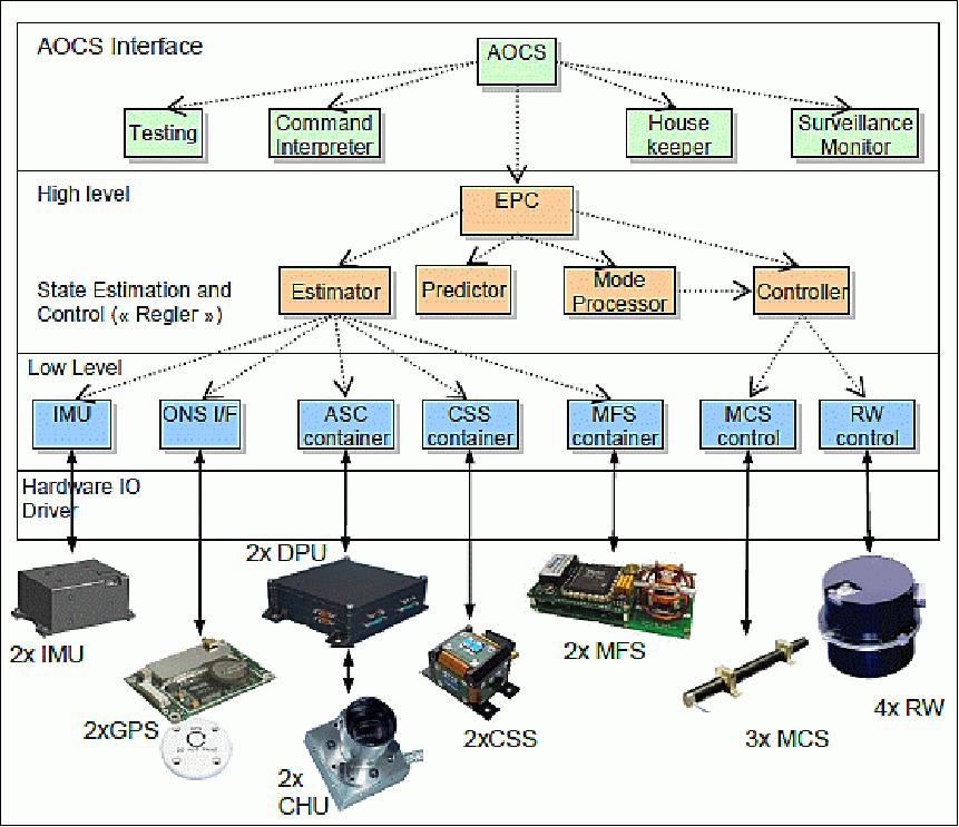
AOCS (Attitude and Orbit Control Subsystem): The AOCS features multiple functional and hardware redundancies; it consists of two star sensors, two IMUs, two magnetometers, 2 sets of course sun sensors, 4 reaction wheels, a redundant magnetic coil systems, 2 GPS receiver systems and an ONS (Onboard Navigation Subsystem), based on an orbit propagator and TLE (Two Line Element) information, which runs as software application on the OBC. The AOCS algorithm uses a "state estimation" system; it is controlled in the OBC by autonomous monitoring of the "timings" of all AOCS threads and processes. This is essential for a seamless filtering and processing of AOCS data.
The robustness of the TET AOCS is secured by redundancy of its hardware components and a "configuration management system" to handle the redundancy by software, this provides onboard failure detection and diagnosis. Its robust control loop permits to react against perturbation and component anomaly with sufficient stability margin.
TCS (Thermal Control Subsystem): The TET bus is equipped with a semi-active TCS. The MLI (Multi-Layer Isolation) isolates the satellite from the space environment, and the TET radiator is the only thermal interface to space. The size of the radiator was defined by a thermal analysis and related tests. The radiator allows the complete radiation of all thermal energy into free space during the "hot" phases (when maximum of energy is generated in the satellite, flying in the sun-illuminated part of the orbit), and, on the other hand, it is small enough to prevent an out cooling of the system during "cold" phases (when only minimum of energy is dissipated in the satellite, flying in the Earth shadow). In addition, the system is equipped with thermal sensors and heaters on the batteries to prevent a temperature below -10°C. For the payload platform, an operational temperature range between -10°C and +30°C is maintained at all times.
RF communications: The S-band transmission system uses a CCSDS (Consultative Committee for Space Data Systems) compatible implementation with two hot redundant receivers (with 4 kbit/s uplink data rate) and two cold redundant transmitters with a downlink high bit rate of 6 Mbit/s. The two receiver/transmitter pairs can be switched to the omnidirectional low gain antenna system or the high gain antenna.
Additionally, BIROS will contain a technical experiment using a hardware VHF modem, whereby communicating with an ORBCOMM satellite (altitude 800 km), it will be possible to inform directly the ground users via email and SMS about an on-board detected hot-spot with the concerning geo-location.
Spacecraft envelope (length x width x height) | 670 x 580 x 880 mm3 |
Payload envelope (length x width x height) | 460 x 460 x 428) mm3 |
Mass of TET-X spacecraft bus | 70 kg |
Mass of BIROS spacecraft | ~130 kg |
Payload mass | ~ 50 kg |
Type of attitude stabilization | 3-axis stabilized |
Accuracy of attitude alignment (pointing accuracy) | 2 arcmin |
Satellite pointing knowledge | ~ 10 arcsec |
Jitter of the attitude control system | ~ 12 arcsec/s |
Satellite on orbit position knowledge | < 10 m (optional <1 m filtered) |
Satellite velocity accuracy | < 0.1 m/s |
Pointing directions of payloads (sensors) or solar arrays | Sun, Earth, nadir, zenith, in flight direction and deep space |
Power consumption - average (payload and payload support system) | up to 80 W |
Power consumption - peak (payload and payload support system) | Up to160 W per 20 minutes |
TC uplink data rate | 4 kbit/s |
TM data rate downlink | 2 Mbit/s (S-band) |
Payload data downlink rate via separate payload transmitter | Baseline 25 Mbit/s (X-band), |
Design life | 3 to 5 years |
Reliability | 0.7 for 5 years |
Microjet Propulsion System
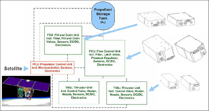
Microjet, developed by AIG (Aerospace Innovation GmbH) of Berlin, is a modularly designed propulsion system for Nanosatellites and Microsatellites based on the gas-resistojet-concept. It consists of a PST (Pressure Tank Unit) with nitrogen which is filled or drained, respectively, through a FDU (Fill and Drain), a FCU (Flow Control Unit) responsible for the control of correct propellant mass flow, as well as one or more THUs (Thruster Units). Each of these THUs contains a pulse valve and a nozzle for the actual thrust generation. Additionally, according to the definition of the Resistojet-concept, an electrical resistance-heating element might be applied for higher performance demands. The entire propulsion system is controlled by the PCU (Propulsion Control Unit), which can also be resigned of, if the satellite itself is capable to control the Microjet propulsion subsystems. 12)
Working fluid | Nitrogen (N2) at max. expected operating pressure of 310 bar (MEOP) |
Pressure vessels | 310 bar composite over-wrapped pressure vessels from 1 to 9 liter available |
Electric Power and Isp | 35.9 W (Resistojet mode incl. 20 W for heating, ca. ce=952 m/s) |
Thrust | Option A (Resistojet mode): ca.. 67 mN per thruster |
Vcc (nominal) | 18 V – 24 V |
Status | EQM qualified in 2014, FM in progress, application in space in 2016 |
Remarks | Incl. DC/DC converters, pressure transducers and temperature sensors, ECSS based development and testing, no pyrotechnic valves, no ITAR parts, COTS design. |
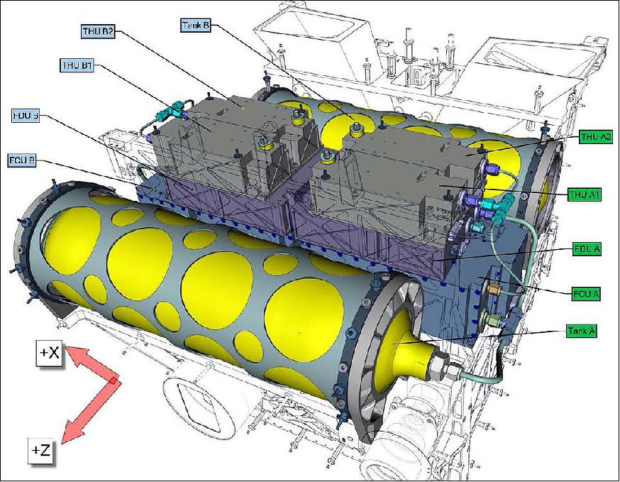
The Microjet 2000 shall enhance the BIRD system's maneuvering capabilities within the FireBird Mission. Due to redundancy requirements, the contemporary satellite configuration contains two entirely independent propulsion subsystems. However, Microjet's modular design specifications allow almost random positioning. In order to ensure the reliability of the BIROS propulsion system, each Microjet subsystem is equipped with two THUs. Here, the BIROS satellite bus controls the Microjet operation. The entire Microjet 2000 system measures ca. 55 cm x 49 cm x 18 cm and has a total mass of ca. 21 kg.
In the spring of 2015, the Microjet 2000 propulsion system for the BIROS satellite is being qualified in close corporation with DLR (German Aerospace Center). After the development of the STM (Structure and Thermal Model) and successful ground qualification of the Microjet 2000 EQM (Engineering Qualification Model), the FM (Flight Model) undergoes acceptance testing.
OSIRIS Development Status
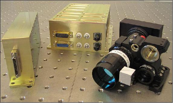
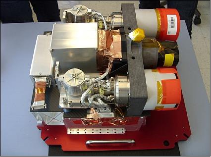
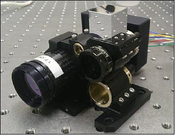
• April 2015: After successful space qualification with the qualification model including thermal vacuum test, radiation test and vibration test, the FMs (Flight Models) have been integrated. Figure 9 shows the FMs after integration, calibration and flight model acceptance vibration test. Especially this measurement is essential for OSIRIS as it gives information about the final angular correlations between the OSIRIS coordinate system and the satellite's attitude control coordinate system. Both coordinate systems can be referenced by alignment cube measurements.
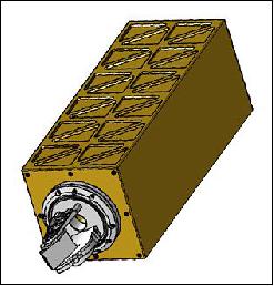
While the OSIRIS system for the BiROS satellite uses the attitude control system for pointing towards the ground station, further OSIRIS development steps will be equipped with a pointing assembly to ensure independent operation between payloads and the optical data link. In the next OSIRIS version OSIRISv3, data rates up to 10 Gbit/s are foreseen at a maximum power consumption of 50 W and a maximum system mass of 5 kg. Figure 10 shows a first CAD model of a potential OSIRISv3 for a small satellite platform.
• The Flight Model is now (spring 2014) to be integrated and ready for launch of the BIROS satellite, scheduled for 2015. The first measurement campaigns to the optical ground stations of DLR will take place thereafter.
• The OSIRIS hardware developed at DLR enables high data rate downlinks from small LEO satellites. The laser terminal is equipped with two downlink laser systems with up to 1 Gbit/s and an optical uplink channel with up to 1 Mbit/s, which is orders of magnitudes higher than currently used RF links. The OSIRIS Qualification Model passed the space qualification tests successfully.
Launch
The BIROS minisatellitewas launched as a secondary payload on June 22, 2016 (03:56 UTC) aboard a PSLV vehicle of ISRO (PSLV-C34 flight) from SDSC (Satish Dhawan Space Center) SHAR (main launch center of ISRO on the south-east coast of India, Sriharikota). The CartoSat-2C mission was the primary payload on this flight with a launch mass of 727.5 kg. The total mass of all satellites onboard was 1288 kg. 13) 14) 15)
BIROS was originally planned to launch in the fall of 2015. This date was shifted recently by the launch provider.
Orbit: Sun-synchronous orbit, altitude = 515 km, inclination = 97.56º.
The secondary payloads (19 satellites) on this flight were:
• SkySat-3, an imaging minisatellite of Terra Bella of Mountain View, CA, USA.
• GHGSat, a microsatellite (15 kg) of GHGSat Inc., Montreal, Canada
• BIROS (Bi-spectral InfraRed Optical System), a minisatellite 130 kg) of DLR, Germany.
- BIROS carries onboard the picosatellite BEESAT-4 (Berlin Experimental and Educational Satellite-4) of TU Berlin(1U CubeSat, 1 kg) and release it through a spring mechanism [ejection by SPL (Single Picosatellite Launcher) after the successful check-out and commissioning of all relevant BIROS subsystems]. After separation, it will perform experimental proximity maneuvers in formation with the picosatellite solely based on optical navigation.
• M3MSat (Maritime Monitoring and Messaging Microsatellite) of DRDC (Defence Research and Development Canada) and CSA (Canadian Space Agency).
• LAPAN-A3, a microsatellite (115 kg) of LAPAN (National Institute of Aeronautics and Space of Indonesia) Jakarta, Indonesia.
• SathyabamaSat, a 2U CubeSat of Sathyabama University (1.5 kg), India.
• Swayam, a 1U CubeSat of the College of Engineering (1 kg), Pune, India.
• 12 Flock-2p Earth observation satellites (3U CubeSats) of Planet Labs (each with a mass of 4.7 kg), San Francisco, CA.
Mission Status
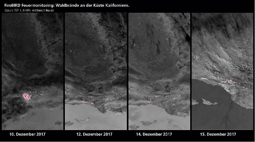
• December 20, 2017: Emergency services in the US state of California are still fighting fierce forest fires. Severe drought and strong winds have allowed the fires to spread. The FireBIRD (Fire Bispectral InfraRed Detector) mission run by the German Aerospace Center (Deutsches Zentrum für Luft- und Raumfahrt; DLR) consists of a pair of satellites – TET-1 (Technology Experiment Carrier) and BIROS (Bispectral Infrared Optical System). These detect high-temperature events from space. On Sunday, 10 December, TET-1 registered a major seat of fire near the town of Ventura, north of Los Angeles, on the US Pacific coast. Further data was recorded over the days that followed. After analyzing initial imagery, DLR researchers realized that in central areas the fire burned more intensely and thus radiated more energy than was the case with the major forest fires that occurred in Chile, Portugal and British Columbia in 2016 and 2017. Scientists calculated a radiation energy of up to 18 megawatts for individual zones within the overall area affected by fires in California. The radiation energy of the aforementioned fires elsewhere in the world was only around half as high. 16)
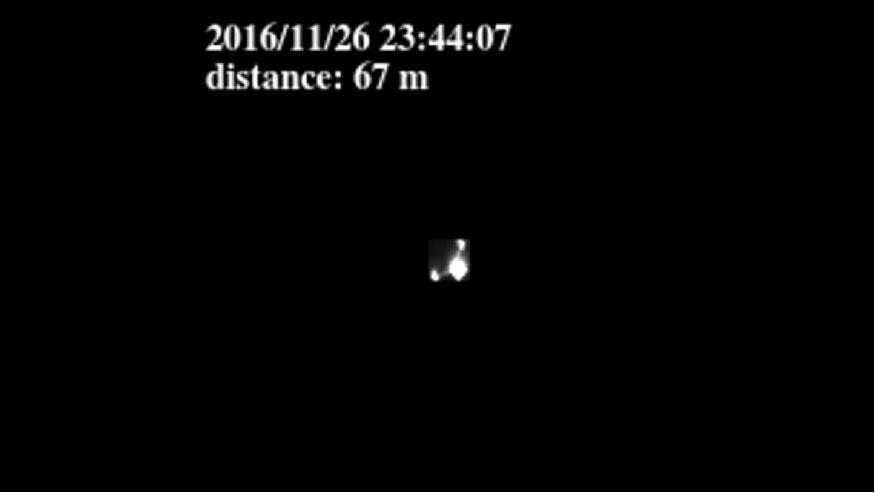
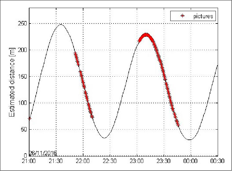
•December 7, 2016: Conclusion of the AVANTI experiment: Final autonomous approach to 30 m. Based on the confidence gained during the first autonomous approach, a second rendezvous has been exercised during the few remaining days of the experiment. The objective was to explore the behavior of the autonomous vision-based GNC system at mid to close range. The main difficulty here consists in tuning properly the GNC parameters to cope with the peculiarities of the close approach. At this distance, the target is so bright that no star is visible anymore in the picture. As a result, it becomes impossible to determine precisely the orientation of the camera using the celestial objects present in the image background. The onboard navigation has thus to rely on the onboard estimate of the spacecraft attitude, which can be affected by a large error (up to several degrees) depending on the availability of the other star tracker. This additional source of error has to be reflected in the filter measurement noise: even if the target centroiding performance is still at the subpixel level (1 pixel corresponds here to 80 arcsec), the onboard attitude error leads to a global measurement noise of about 1 degree (3600 arcsec), which is more than one order of magnitude larger than what we were used to see at far range. 17)
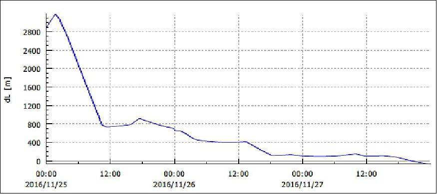
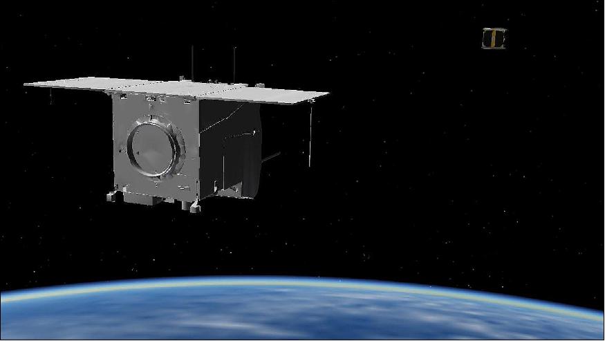
• December 7, 2016: A cosmic cat and mouse game. For the first time in the history of space exploration, scientists at DLR (German Aerospace Center) have demonstrated in a real space experiment how a satellite can approach a counterpart fully autonomously, making use of only optical (vision-based ) navigation. This highly sophisticated technology was demonstrated on the Earth observation satellite BIROS (Bi-spectral InfraRed Optical System) as part of the AVANTI (Autonomous Visual Approach Navigation and Target Identification) experiment, during which the satellite was able to draw to within 50 m of its target's object. BEESAT-4, a CubeSat dispatched by BIROS last September, was used as a target satellite in the experiment. BIROS was fitted with a spring-loaded deployer mechanism that ejected the CubeSat at a velocity of 1.5 m/s. In addition, DLR scientists and engineers equipped the minisatellite BIROS with a propulsion system that enables the washing machine-sized, roughly 130 kg satellite to rapidly execute any slew maneuvers. During the AVANTI experiment, BIROS learned how to specifically modify its trajectory and use a camera head of the star tracker to search for and 'keep an eye' on the CubeSat. Unlike in conventional orbital maneuvers, the satellite did not receive any commands from the control center in Oberpfaffenhofen, relying instead on the on board AVANTI experiment programs. Equipping satellites with this capability could become extremely important in the future, as it would allow them to detect and later capture old and inactive satellites and space debris. 18) 19)
• November 3, 2016: A unique experiment has been devised by DLR/GSOC. The AVANTI experiment (Autonomous Visual Approach Navigation and Target Identification) is intended to demonstrate how a satellite can detect a spacecraft in space and approach it autonomously. This capability will be necessary in the future for capturing old and inactive satellites, as well as space debris, and bringing them into a safe orbit. To this end, scientists are using the recently launched BIROS satellite and the BEESAT-4 CubeSat that it deployed. The technology for the experiment is based on BIROS, which is meant to represent the 'catcher' satellite. The small BEESAT-4 acts as an 'inactive' satellite in the experiment. AVANTI will fully autonomously calculate an optimized flight path for BIROS so that it can approach the target object. DLR researchers are using improved algorithms for the steering, navigation and control of the 'catcher'. One after the other, AVANTI performs a series of measurements. Then, the star camera acquires images of the target area. An image processing program analyses the recordings, identifies the flying object and measures the bearing to the object. Subsequently, the relative real-time navigation algorithm is fed with information from the bearing measurements and the calibrated flight maneuver data with which the relative movement of BEESAT-4 can be calculated. The resulting relative position and speed of the target object can ultimately be used for maneuver planning to program a safe and efficient flight path to reach BEESAT-4.
• September 9, 2016: The BIROS (Bi-Spectral Infrared Optical System) fire detection satellite released BEESAT-4 (Berlin Educational and Experimental Picosatellite) into space 515 km above the Norwegian Svalbard archipelago. The CubeSat was developed and built by staff and students at the Technical University of Berlin (TU Berlin) and was supported by the DLR Space Administration. BEESAT-4 should now be able to use the on-board Phoenix GPS receiver to gather precise position and orbit determination information, as well as take series of photographs and individual images of Earth's surface with a special camera to confirm the position of the satellite. The telemetry and image data will then be sent to the BIROS 'mother ship' that then forwards it to the TU Berlin ground station for analysis. 21)
Sensor Complement
Optical IR Payload
The optical payload, designed and developed at DLR, consists of an assembly of three pushbroom cameras, one in the VNIR (Visible Near Infrared) range and two imagers in the infrared region. The overall objective is the detection and quantitative analysis of HTE (High Temperature Events) like wildfires and volcanoes. 22) 23) 24)
Time is essential to support most effectively the decisions of fire managers in fire suppression planning, crew mobilization & movement. Therefore, on-board processing of fire front attributes, including geo-referencing and their direct transmission to the user on ground is a challenging task for small satellites, but it shall be technically feasible.
Key procedures for on-board fire detection and analysis are pre-processing and extraction of fire attributes. The pre-processing includes:
- Radiometric correction (using system correction files)
- Inter-channel co-registration (using system correction files), and
- Geo-referencing (using on-board navigational information).
The fire detection and analysis extraction of fire attributes includes:
- Background classification for threshold adaptation: land, water, clouds, sun glints
- Hotspot detection (based principally on the BIRD algorithm)
- Consolidation of hot pixels in hot clusters
- Extraction of attributes of hot clusters, such as coordinates, FRP (Fire Radiative Power) and, optionally, fire line strength, effective fire temperature and area.
Parameter | VNIR camera with 3 CCD-line FPA | 2 Bi-spectral infrared cameras with cooled linear detector arrays |
Spectral wavelengths | Line 1: 460-560 nm (green) | MWIR: 3.4 - 4.2 µm |
Focal length | 90.9 mm | 46.39 mm |
FOV (Field of View) | 19.6º | 19º |
F number | 3.8 | 2.0 |
Detector type | CCD-line array | CdHgTe line arrays |
Detector cooling | Passive, 20ºC | Stirling, 80-100 K |
Detector element size | 7 µm x 7 µm | 30 µm x 30 µm |
No of pixels | 3 x 5164 | 2 x 512 staggered |
Data quantization | 14 bit | 14 bit |
Ground pixel width | 42.4 m | 356 m |
Sample width | 42.4 m | 178 m |
Swath width | 211 km | 178 km |
In-flight calibration | None | Use of a removable calibration flap |
Data interface | LVDS SpaceWire | LVDS SpaceWire |
Data rate | 44 Mbit/s (max), 11 Mbit/s (nominal) | 350 kbit/s |
Data volume | 330 MByte/min, 83.4 MByte (nominal) | 5 MByte/min |
Instrument mass | < 12 kg | |
OSIRIS (Optical Space Infrared Downlink System)
The OSIRIS project of DLR's Institute of Communications and Navigation has the goal to develop an optical communications technology optimized for small satellites. COTS (Commercial-of-the-Shelf) hardware is used to obtain a cost-effective approach; this is suitable to fulfill the scientific goals like atmospheric measurements, experiments with adaptive optics systems and to prove concepts like optical ground station diversity. 25) 26) 27) 28)
The goal of the experimental optical communications system OSIRIS is to demonstrate technologies enabling high-rate data links with up to 10 Gbit/s applicable to small satellites, which are typically restricted to RF links in S-band with only a few Mbit/s of available data rate.
OSIRIS for BiROS carries two separate laser sources with an IM/DD (Intensity Modulation/Direct Detection) modulation scheme at 1550 nm; it has been designed for a data rate of 1 Gbit/s, which is an increase of a factor 500 compared to the 2 Mbit/s S-band link available for BiROS. Pointing and tracking is accomplished by steering the full satellite, resulting in a simple and robust system design without mechanics. Hence, a tracking sensor is installed as well, featuring a beacon laser to aid the tracking of the satellite.
The optical signal is transmitted by two collimators with different divergence angles. This redundant approach enables an open loop pointing, based on the satellite's attitude sensors, and a closed loop pointing using the attitude sensors together with the OSIRIS tracking sensor. Wherever possible, all electronics have been designed one-error-tolerant. Figure 18 shows the link budget versus elevation for the EDFA (Erbium Doped Fiber Amplifier), which is one of the two laser sources of the system.
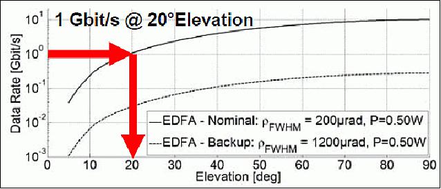
With the current setup and a 60 cm ∅ OGS (Optical Ground Station), a data rate of 1 Gbit/s can be reached at an elevation angle of 20º. The two divergence angles (200 µrad and 1200 µrad, both FWHM values) are still relatively large for this experiment and can be further reduced in future developments. This gain will allow for higher data rates or simply an improved link margin.
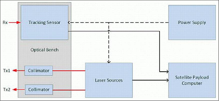
OSIRIS Instrumentation and Setup
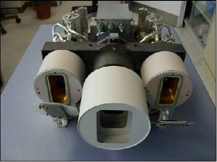
The OSIRIS payload for DLR's BIROS satellite consists of three main parts as shown in Figure 19: The tracking sensor with its electronics, that receives and processes the beacon signal from the ground station and provides the tracking signal for the satellite payload computer and the attitude control. The tracking sensor is mounted on the same optical bench together with the transmitter collimators. The collimators are connected with the laser sources, providing two different laser signals.
Tracking sensor: The OSIRIS tracking sensor mainly consists of a quadrant type InGaAs PIN diode with an active area diameter of d=1mm. This detector is an integral part of the sensor and is mounted within a telescope parallel to the sending laser collimators on the optical bench. During operation, the ground station beacon laser illuminates the satellite and with the detector. This beacon signal is modulated with tracking and data signals. The resulting spot on the sensor is defocused to a diameter of ~d/2 in order to achieve a large FOR (Field of Regard). Consequently, every quadrant causes a current proportional to the incoming optical power. Since the optical power in the range of a few 100 pW is expected along with a small current, the analog signal processing is regarded as challenging.
The critical parts of the analog circuit are placed close to the PIN (Positive Insulator Negative) diode to reduce EMI (Electromagnetic Interference) and parasitic effects. The large area of the PIN diode allows on the one hand a high resolution with acceptable mechanical tolerances. On the other hand it causes the main problem of this sensor topology: a high junction capacitance. Indeed, a reversal voltage on the diode reduces this effect, but an expected capacitance of ~20 pF per quadrant has to be dealt with. This capacitance, combined with the needed high amplification, reduces very strongly the bandwidth of the sensor. High data rates and rectangular signal wave forms suffer from this restriction. The capacitance also causes circuit instability, which is not discussed in detail. Furthermore, circuit noise is problematic due to the small input signal power. The passband, component values, but also the dimensions of the circuit have to be chosen wisely to achieve optimal results.
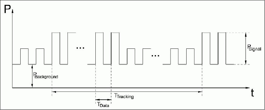
The beacon laser signal is modulated with a high frequency data signal up to 1 Mbit/s. The data signal is mixed with a 10 kHz rectangular signal as shown in Figure 20. This allows a combination of high data rates and sensitive tracking. The basic circuit topology is presented in Figure 21. The four anode connections are used to sense the tracking signal. The small diode current is amplified with four TIA (Transimpedance Amplifier) circuits. In order to remove background light, the signal is then high-pass filtered and a mean value is composed with the use of a rectifier circuit. This value, which is proportional to the incoming light intensity on every single quadrant, is now sampled with a 12 bit resolution. Consequently the alignment of the OSIRIS sensor can be calculated by the satellite bus. These four signal paths are optimized to be noiseless and sensitive, which means that the bandwidth is highly limited and only the 10 kHz tracking signal can be seen. These paths are not suitable for high data rates.
In order to receive data, another TIA structure is placed on the common cathode connection. This circuit has a higher bandwidth and it is optimized for data reception. Here, the total current of all quadrants is sensed, so that one can expect a higher signal current, though the seen junction capacity is also bigger. After an active filter/buffer, a comparator provides a bit decision. For this, the 10 kHz tracking signal needs to be suppressed with a sharp edge high-pass filter. To reduce random switching events, the comparator is implemented with a hysteresis. For this a positive resistive feedback is established. With appropriate resistances, the hysteresis can be set slightly above the noise level. With this measure, the circuit noise doesn't increase for the case of low input power or for tracking without data transmission.
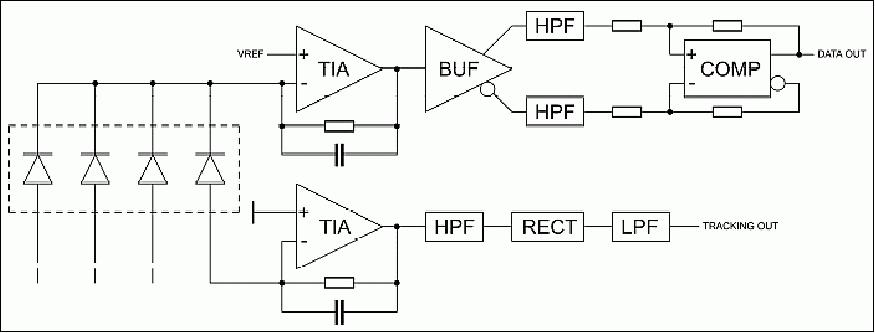
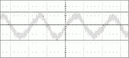
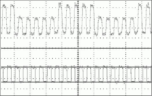
Figure 22 shows the measured output signal of one tracking path. The limited bandwidth leads to the typical RC (Resistance Capacitor) charging waveform. It has to be mentioned, that this RC is correlated with the junction capacitance. Higher reversal voltages allow better values, but also limit the operational range of the system due to the limited output voltage swing of the TIA. Nevertheless, tracking is possible with 70 pW optical input power per quadrant. As it can be seen, the signal to noise ratio is the greater 3dB. Furthermore it can be seen, that high frequencies, which are caused by the transmitted data are suppressed efficiently.
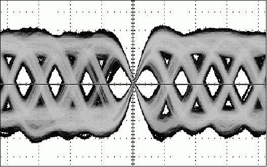
In Figure 23, the received analog data signal is presented in an eye diagram. It can be seen, that the system is able to handle frequencies up to 1 Mbit/s. Figure 24 shows the analog data signal and the digital signal after the bit decision. Here, an uplink frequency of 250 kbit/s is used. The 3dB attenuation can be observed. Furthermore it can be seen, that the data transmission is not disturbed by the tracking signal.
Optical bench: The optical bench is the mount for all optical components of the OSIRIS system. The optical bench consists of the tracking sensor as a receiver for the beacon signal from the ground station and the uplink data channel as well as of two adjustable transmission collimators. To reduce the mass of the optical bench, an aluminum- carbon-fiber-construction has been selected.
The challenge in designing the optical bench is the precise alignment of the three optical axes of the tracking sensor and the two collimators. For the data downlink, two overlapping collimators are used: one collimator with a divergence of 1200 µrad for pointing to the ground station, using the attitude sensors of the satellite and a second collimator with 200 µrad for pointing with the OSIRIS tracking sensor. The requirement for the precision of the alignment of the optical axes of the optical bench depends on the smallest divergence used. The boundary value for the alignment error should be ±3σ, which leads to a maximum misalignment of 30 µrad for the optical axes of the tracking sensor and the collimators.
Standard collimators suffer from a misalignment between the mechanical axis of the housing and the optical axis of the lens system. To reach the goal of a maximum misalignment of 30 µrad, the optical bench is equipped with adjustable collimators that provide the possibility to align the mechanical and the optical axes.
Furthermore the optical bench provides an alignment cube. During calibration measurements, the axes of the tracking sensor and the collimators are measured with respect to the alignment cube. The satellite's attitude control system and star camera is also referenced with an alignment cube, that gives an absolute correlation between the satellites coordinate system and the OSIRIS coordinate system for pointing OSIRIS, dependent on the satellite's attitude control.
The OSIRIS instrument has a total mass of ~5 kg, a power of 50 W (max), and an approximate size of 25 cm x 20 cm x 10 cm.
Space qualification and calibration:
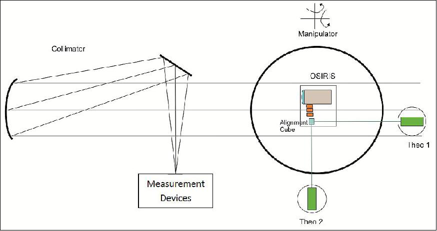
For the integration of OSIRIS as secondary payload on the BIROS satellite, the system had to be space qualified with a vibration, thermal vacuum and radiation test. For a precise pointing to the ground station, the optical axes of the optical bench need to be calibrated to each other and to an alignment cube, giving the reference to the satellite's coordinate system.
Due to the small divergences of the transmission optics, the optical axes need to be calibrated to a maximum misalignment of 0.001º. Therefore, a calibration process has been developed using the calibration laboratory of DLR' Institute for Optical Sensor Systems. Figure 6 shows the calibration setup: a collimator is used to provide OSIRIS with collimated light, acting as the ground station in a later scenario. OSIRIS is positioned with the tracking sensor aligned to the collimator. With a reference spot in the measurement devices, the OSIRIS transmit optics can be co-aligned this reference given by the tracking sensor.
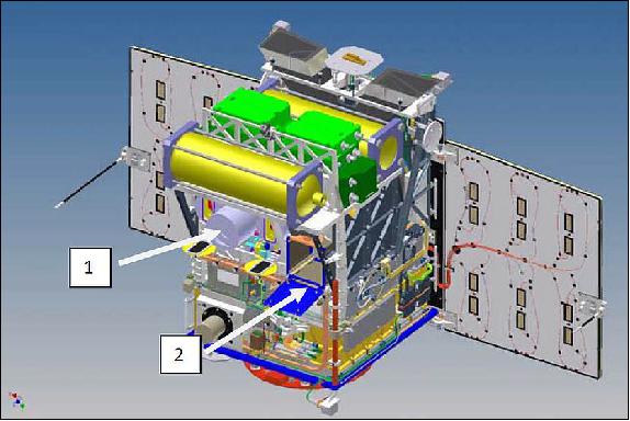
Legend to Figure 27: The primary optical payload is accommodated at location 1, while the OSIRIS laser terminal as secondary payload is accommodated at location 2.
AVANTI (Autonomous Vision Approach Navigation and Target Identification)
Among the various technology demonstrations, BIROS carries onboard the BEESAT-4 picosatellite (1U CubeSat), developed by the Technical University of Berlin. BEESAT-4 will be deployed by means of a spring-based SPL (Single Picosatellite Launcher). 29)
The AVANTI experiment represents the inflight technological demonstration of one of the OOS (On-Orbit Servicing) essential enabling technologies: the capability to approach, identify, rendezvous with a non-cooperative, passive client from large distances (e.g., > 10 km) in an autonomous, fuel efficient, and safe manner. To this end, a fully vision-based approach becomes appealing, since it simplifies an aspect of the servicer spacecraft design by exploiting simple passive low-cost sensors (e.g., optical or infrared cameras) or, as performed in AVANTI, by using a camera head of the star-tracker, already available onboard to fulfill the attitude determination task. 30)
The AVANTI experiment is intended to demonstrate vision-based non-cooperative autonomous rendezvous operations of an active small satellite (BIROS) within separations between 10 km and few hundreds of meters from a picosatellite (BEESAT-4) making use of solely angles-only measurements. The experiment is intended to start after that the BIROS/Picosatellite formation has been brought to an initial safe configuration at a separation within 5 to 10 km and minimal residual drift, in the along-track direction, towards increasing relative distance. This operational task is solely ground-based and performed by the FDS (Flight Dynamics Services) division of GSOC (German Space Operations Center), which is in charge of the orbit determination and control of the FireBird mission (Ref. 4).
AVANTI experiment requirements. The design requirements posed by the AVANTI experiment are hereafter briefly introduced:
1) Relative trajectory at conclusion of the separation and passive safety. The safety concept retained for AVANTI is mainly based on the passive safety of specific relative trajectories. For almost bounded relative orbits, it is achieved by a determined phasing (i.e., (anti-)parallel configuration) and magnitude (i.e., at least 150 m) of the relative eccentricity and inclination vectors. Accordingly, the AVANTI experiment has to start from an almost bounded passively safe relative orbit, whose remaining characteristics are dictated by the following further aspects.
- The mean along-track separation should be within 5 km (to allow eventual radar tracking support and to allow imaging the picosatellite with the camera aligned to the local orbital frame centered on BIROS) and 10 km (to allow detecting Picosatellite luminous spot on the images).
- Finally the maximum acceptable magnitudes of the relative eccentricity and inclination vectors are determined so that the motion of BEESAT-4 fits the FOV (Field of View) of the camera (i.e., opening angle of 6.8° horizontally and 9.15° vertically) at the start of the experiment. A relative orbit presenting these just mentioned characteristics is referred as to experiment ICs (Initial Conditions).
2) Effect of the differential drag perturbation. The choice if the picosatellite should be leading or following BIROS can be decided by looking at the differential drag. The surface to mass ratio of the picosatellite is larger than that of BIROS by factor 2 to 3 (the effective surface of BIROS varies according to the actual attitude mode). This means that the picosatellite will be affected stronger by air drag, decay faster and thus move faster in the along-track direction. If it is ejected such, that it will lead the formation, this effect can be used to increase the safety of the constellation, as the differential drag will always create a natural drift, that increases the along-track separation.
3) Stability of the relative orbit. The stability of the relative orbit is disturbed by the perturbation which is caused by the Earth's oblateness. The J2 effect on the relative eccentricity vector, for SSO orbit 500 km high, amounts to a clock-wise rotation of circa 3.6 º/day. For a bounded and slowly drifting orbit, the J2 effect on the relative inclination vector affects only its y-component according to: Δδiy = 3 γ sin2iδix. Therefore, the separation phase has to establish a relative orbit with the x-component of the relative inclination vector the closest possible to zero. This is achieved by an ejection at the "poles" of the orbit, where the mean argument of latitude u = 90° or u = 270°.
4) Minimization of the separation Δv. Furthermore it is desired to save as much fuel as possible. Hence a strategy which manages to reduce the delta-v consumption would be preferred, but not strictly required. The AVANTI experiment has been assigned a fixed Δv budget. The smaller the amount of propellant is used during the separation and acquisition of ICs, the more is available for the experiment itself.
The preliminary design already addresses the first two requirements. Nevertheless, the assumption to perform just a single thrust with the BIROS propulsion system, in the presence of errors in the execution of both ejection and maneuver, brought to a high expenditure of Δv and a partial satisfaction of the AVANTI ICs. The current analysis, instead, benefits from the possibility to perform more maneuvers and therefore can aim to pursuing the requirement 4. In addition, the introduction of the 3rd prerequisite determines a preference on the candidate locations (i.e., mean argument of latitude) of the picosatellite ejection.
In order to enable the ground-based Picosatellite orbit determination, some tracking data of BEESAT-4 have to be collected. Both satellites, BIROS and BEESAT-4 are equipped with a Phoenix GPS receiver. Nevertheless, this option is not considered a reliable data source, since for BEESAT-4 the GPS receiver is only an experimental payload and it is not clear if and how long after separation it will deliver GPS observations. Equivalently, TLEs (Two-Line-Elements) of the BEESAT-4 orbit might not be available in the time frame of few orbits. The images delivered by the RGB camera onboard BIROS can be processed on-ground to deliver accurate 3D pose estimate at the (sub-)centimeter level.
The subsequent filtering of the relative trajectory allows estimating the velocity increment encountered during the deployment accurate to 0.2% and subsequent relative orbit prediction accurate at the meter level during the following hours. Nevertheless, a precise knowledge of the orbit at later times and the estimate of the effect of the differential drag perturbation are also required, in order to accomplish the maneuver planning to establish the AVANTI ICs. As a consequence, the orbit determination of the Picosatellite has to be performed based on the solely remaining option of on ground observations: radar-tracking campaigns.
To this end, it is scheduled to track the formation with the radar tracking station TIRA (Tracking and Imaging Radar) located at the FGAN site in Wachtberg near Bonn, Germany. Due to the large difference in size of the two spacecraft, TIRA will only be able to distinguish them, when they have reached a separation of at least 5 km. Furthermore, a reliable orbit determination is only possible, when several passages have been tracked over an interval of 12 hours.
Ground Segment
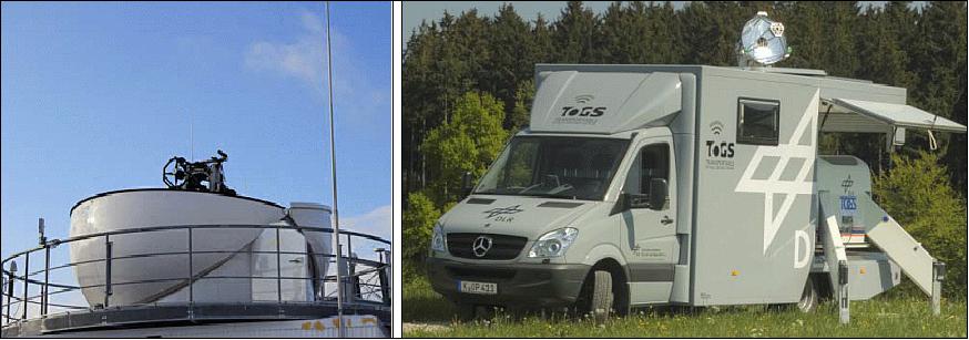
Two optical ground stations will be available for the demonstration experiments with OSIRIS: OGS-OP (Optical Ground Station Oberpfaffenhofen), as well as the TOGS (Transportable Optical Ground Station). Both are shown in Figure 28. The optical-bench setup of OGS-OP will focus on an installation of measurement devices for characterizing the atmospheric downlink channel, while TOGS will focus on data reception and BER measurements.
OGS Diversity and Achievable Data Throughput:
Optical satellite downlinks suffer from limited availability due to cloud coverage. To mitigate these effects, a network of optical ground stations must be used to make operational use of optical data links for direct downlinks. The optimization of suitable OGS networks is a current research topic, and standardization efforts are pursued by the CCSDS (Consultative Committee for Space Data Systems) to ensure interoperability of free-space optical communication systems around the globe.
For the present experiments with BIROS, a simple estimation based on the BIROS orbit and single-site cloud-availability statistics has been done to obtain a rough throughput figure. The result is of course depending on the minimum link elevation and is compared to the data throughput achieved with the 2 Mbit/s S-band link. Oberpfaffenhofen, Neustrelitz, Adelaide/Australia and Izaña/Tenerife have been considered as ground station sites. Each ground station contact above the corresponding minimum elevation is considered for data transmission. Effects due to scattered clouds (resulting in links that are only partly available) or restrictions due to limited satellite memory have not been considered. The results are shown in Figure 29.
With a minimum link elevation of 5º and an availability of 100%, and making use of each contact with DLR's RF ground station in Weilheim near Oberpfaffenhofen, the S-band RF link enables the transmission of roughly 4 Gbit per day. Even despite the poor cloud availability of Oberpfaffenhofen and the comparably high minimum link elevation of 20º, the optical link enables the transmission of roughly 200 Gbit per day with only Oberpfaffenhofen as ground station. By using both OGS-OP and TOGS for diversity, the theoretical mean daily throughput is further increased and reaches values of roughly 1 Tbit per day.
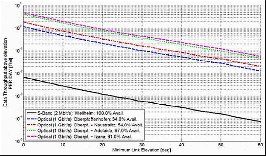
Figure 29: Mean daily data throughput for BIROS with different data links (RF, optical) and OGS setups versus minimum link elevation (image credit: DLR)
References
1) Benjamin Wille, Maria Theresia Wörle, Christoph Lenzen, "VAMOS – Verification of Autonomous Mission Planning On-board a Spacecraft," 19th IFAC Symposium on Automatic Control in Aerospace, Würzburg, Germany, Sept. 2-6, 2013, URL: [web source no longer available]
2) Maria Theresia Wörle, Christoph Lenzen, "Ground Assisted Onboard Planning Autonomy with VAMOS," IWPSS (International Workshop on Planning and Scheduling for Space), Moffett Field, CA, USA, March 25-27, 2013, URL: http://robotics.estec.esa.int/IWPSS/IWPSS_2013
/IPWSS_2013_Proceedings/27_Worle.pdf
3) Gabriella Gaias, "Onboard Maneuver Planning for the Autonomous Vision Approach Navigation and Target Identification (AVANTI) experiment within the DLR FireBird mission," Toulouse, France, Oct. 31, 2013, URL: http://homepages.laas.fr/clouembe/WSrdv/gaias.pdf
4) Martin Wermuth, Gabriella Gaias, "Operational Concept of a Picosatellite Release from a LEO Satellite," Proceedings of the 25th International Symposium on Space Flight Dynamics, Munich, Germany, Oct. 19-23, 2015, URL: http://issfd.org/2015/files/downloads/papers/150_Wermuth.pdf
5) S. Roemer, S. Eckert, "The TET-X and TET-XL — Evolution of the TET-1 Satellite Platform," DLRK (Deutscher Luft- und Raumfahrtkongress), Stuttgart, Germany, Sept. 10-12, 2013
6) Stephan Roemer, Silke Eckert, "Evolution and Usage of the TET satellite platform," 2013, AFW (information provided by Stephan Roemer).
7) Hubert Reile, Eckehard Lorenz, Thomas Terzibaschian, "The FireBird mission - a scientific mission for Earth observation and hot spot detection," Proceedings of the 9th IAA Symposium on Small Satellites for Earth Observation, Berlin, Germany, April 8-12, 2013, URL: [web source no longer available]
8) W. Halle, W. Bärwald, C. Raschke, T. Terzibaschian, "The DLR -Satellite BIROS in the FireBIRD Mission," Proceedings of the 4S (Small Satellites Systems and Services) Symposium, Port Petro, Majorca Island, Spain, May 26-30, 2014
9) Winfried Halle, M. Hetscher, Thomas Terzibaschian, "The DLR-Satellite BIROS for Fire-Detection and Technological Experiments," 10th IAA Symposium on Small Satellites for Earth Observation, Berlin, Germany, April 20-24, 2015, paper:IAA-B10-0201, URL: [web source no longer available]
10) Winfried Halle, Thomas Terzibaschian, Klaus-Dieter Rockwitz, "The DLR-Satellite BIROS for Fire-Detection and Technological Experiments," 20.04, 2015, URL: https://www.dlr.de/iaa.symp/Portaldata
/49/Resources/dokumente/archiv10/pdf/0201.pdf
11) Winfried Halle, Eckehard Lorenz, "The DLR FireBird Constellation," Proceedings of the 4S (Small Satellites, System & Services) Symposium, Valletta, Malta, May 30-June 3, 2016
12) Harry Adirim, Matthias Kreil, Michael Kron, Andrei Mitrofanow, Winfried Halle, Matthias Lieder, Wolfgang Bärwald, Steffen Babben, Thomas Terzibaschian, "Innovative Modular Propulsion Systems for Small Satellites," 10th IAA Symposium on Small Satellites for Earth Observation, Berlin, Germany, April 20-24, 2015, paper: IAA-B10-1106P
13) "PSLV-C34 Successfully Launches 20 Satellites in a Single Flight," ISRO, June 22, 2016, URL: http://www.isro.gov.in/update/22-jun-2016
/pslv-c34-successfully-launches-20-satellites-single-flight
14) "BIROS fire detection satellite successfully launched into space," DLR, June 22, 2016, URL: http://www.dlr.de/dlr/en/desktopdefault.aspx
/tabid-10081/151_read-18339/year-all/#/gallery/23462
15) E. Lorenz, S. Mitchell, T. Säuberlich, C. Paproth, W. Halle, O. Frauenberger, "Remote Sensing of High Temperature Events by the FireBird Mission," Proceedings of ISRSE (36th International Symposium on Remote Sensing of Environment), Berlin, Germany, May 11-15, 2015, Editor(s): G. Schreier, P. E. Skrovseth, and H. Staudenrausch, URL: http://www.int-arch-photogramm-remote-sens-spatial-inf-sci.net
/XL-7-W3/461/2015/isprsarchives-XL-7-W3-461-2015.pdf
16) "FireBIRD monitors forest fires in California," DLR, 20 Dec. 2017, URL: http://www.dlr.de/dlr/en/desktopdefault.aspx
/tabid-10081/151_read-25507/#/gallery/29433
17) "The AVANTI-Experiment, " DLR, Dec. 7, 2016, URL: http://www.dlr.de/rb/en/desktopdefault.aspx/tabid-11685/20432_read-48081/
18) "BIROS demonstrates autonomous rendezvous in space using only image data," DLR, Dec. 7, 2016, URL: http://www.dlr.de/dlr/en/desktopdefault.aspx
/tabid-10081/151_read-20360/year-all/#/gallery/25205
19) "Conclusion of the experiment: Final autonomous approach to 30m," DLR, 7 Dec. 2016, URL: http://www.dlr.de/rb/en/desktopdefault.aspx/tabid-11685/20432_read-48081/
20) "Rendezvous with a satellite," DLR, Nov. 3, 2016, URL: http://www.dlr.de/dlr/en/desktopdefault.aspx
/tabid-10894/1599_read-19916/year-2016/#/gallery/24880
21) "DLR fire detection satellite BIROS successfully releases BEESAT-4 picosatellite into space," DLR, Sept. 9, 2016, URL: http://www.dlr.de/dlr/en/desktopdefault.aspx
/tabid-10212/332_read-19203/year-all/#/gallery/24214
22) Stephan Roemer, Winfried Halle, "TET-1 and BIROS A semi-operational Fire Recognition Constellation," UN/Austria/ESA Symposium on Small Satellite Programs for Sustainable Development: Payloads for Small Satellite Programs, Sept. 21-24, 2010, Graz, Austria
23) "Exposé, BIROS (Berlin InfraRed Optical System)," information provided by Winfried Halle of DLR
24) "TET-Payload,", DLR, URL: http://www.dlr.de/os/desktopdefault.aspx/tabid-7046/11773_read-27676/
25) Christopher Schmidt, Martin Brechtelsbauer, Fabian Rein, Christian Fuchs, "OSIRIS Payload for DLR's BiROS Satellite," Proceedings of ICSOS 2014 (International Conference on Space Optical Systems and Applications), Kobe, Japan, May 7-9, 2014
26) Martin Brechtelsbauer, Christopher Schmidt, Peter Becker, Christian Fuchs, "Application of an optical data link on DLR's BIROS satellite," SpaceOps 2013 Workshop, Laurel MD, USA, June 11-13, 2013
27) "Close collaboration in optical communication between space and Earth," DLR, April 16, 2014, URL: http://www.dlr.de/dlr/presse/en/desktopdefault.aspx
/tabid-10172/213_read-10018/year-all/#gallery/14363
28) Christopher Schmidt,Martin Brechtelsbauer, Fabian Rein, Christian Fuchs, Axel Lauterbach, David Krutz, Ilse Sebastian, Matthias Lieder, Friedrich Schrandt, "OSIRIS Payload on DLR's BiROS Satellite," 10th IAA Symposium on Small Satellites for Earth Observation, Berlin, Germany, April 20-24, 2015, paper: IAA-B10-1312P
29) Martin Wermuth, Gabriella Gaias, Simone D'Amico, "Safe Picosatellite Release from a Small Satellite Carrier", Journal of Spacecraft and Rockets, Vol. 52, No. 5 (2015), pp. 1338-1347, doi: 10.2514/1.A33036
30) G. Gaias, J.-S. Ardaens, T. Terzibaschian, "Paving the Way for Future On-Orbit Servicing Missions: the AVANTI Experiment," Proceedings of the 25th International Symposium on Space Flight Dynamics, Munich, Germany, Oct. 19-23, 2015, URL: http://issfd.org/2015/files/downloads/papers/122_Gaias.pdf
Spacecraft Launch Mission Status Sensor Complement Ground Segment References Back to top