Copernicus: Sentinel-1
EO
ESA
Ocean
Multi-purpose imagery (ocean)
Sentinel-1 is a constellation of two imaging radar satellites operated by ESA. Sentinel-1B experienced an anomaly which rendered it unable to deliver radar data in December 2021, and the launch of Sentinel-1C is planned for 2023.
Quick facts
Overview
| Mission type | EO |
| Agency | ESA, COM |
| Mission status | Operational (nominal) |
| Launch date | 03 Apr 2014 |
| Measurement domain | Ocean, Land, Snow & Ice |
| Measurement category | Multi-purpose imagery (ocean), Multi-purpose imagery (land), Vegetation, Landscape topography, Ocean topography/currents, Sea ice cover, edge and thickness, Soil moisture, Snow cover, edge and depth, Ocean surface winds, Ocean wave height and spectrum |
| Measurement detailed | Ocean imagery and water leaving spectral radiance, Land surface imagery, Vegetation type, Ocean surface currents (vector), Land surface topography, Wind vector over sea surface (horizontal), Sea-ice cover, Snow cover, Soil moisture at the surface, Wind speed over sea surface (horizontal), Iceberg fractional cover, Significant wave height, Bathymetry, Dominant wave direction, Sea-ice type, Dominant wave period, Above Ground Biomass (AGB) |
| Instruments | C-Band SAR |
| Instrument type | Imaging microwave radars |
| CEOS EO Handbook | See Copernicus: Sentinel-1 summary |
Related Resources

Summary
Mission Capabilities
Both Sentinel-1 satellites are identical and have the C-SAR (C-band Synthetic Aperture Radar) onboard. This instrument is composed of the SAR Electronics Subsystem (SES) in charge of radar command and data handling, and the SAR Antenna Subsystem (SAS) in charge of signal radiation and reception. The C-SAR has four observation modes each with a different swath and resolution to suit their purpose: Stripmap (SM), Interferometric Wide swath (IW), Extra Wide swath (EW), and Wave (WV) mode.
The satellites are used for the monitoring of sea and land ice, surveillance of oil spills and ships, monitoring of marine wind and waves, monitoring of land surface motion risks, and the mapping of forest, water, and soil management. SM mode is designed to support ERS (European Remote Sensing) and Envisat missions; IW mode is the default mode over land; EW mode is designed for maritime, ice, and polar zone observation services where wide coverage and short revisit times are demanded; and WV mode is the default mode over the open ocean.
Performance Specifications
SM mode has an 80 km swath and 5 m spatial resolution; IW mode has a 250 km swath and a 5 m x 20 m resolution; EW mode has a 400 km swath and a 25 m x 100 m resolution, and WV mode takes 20 m x 20 m images at 100 km intervals with a resolution of 5 m x 20 m. The C-SAR has a centre frequency of 5.405 GHz.
The two satellites follow the same sun-synchronous orbit with an inclination of 98.2° but are 180° out of phase. The satellites are situated at an altitude of 693 km and have a period of 98.7 minutes.
Space and Hardware Components
The PRIMA (Piattaforma Italiana Multi Applicativa) bus consists of the propulsion module (PPM) which carries all propulsion equipment, the service module (SVM) which carries all other necessary equipment to stay operational, and the payload module (PLM) which contains the C-SAR and other secondary payloads. SVM contains a variety of subsystems that control the thermal environment, power generation and storage, orbit path, and payload data handling and transmission (PDHT). The PDHT subsystem has a storage capacity of 1410 Gbit and a 520 Mbit/s X-band downlink capacity.
On 23 December 2021, Sentinel-1B experienced an anomaly related to the instrument electronics power supply provided by the satellite platform, leaving it unable to deliver radar data. As a consequence, ESA and EC announced the end of the Sentinel-1B mission on 3 August 2022, noting that plans are in force to launch Sentinel-1C as soon as possible.
Copernicus: Sentinel-1 — The SAR Imaging Constellation for Land and Ocean Services
Sentinel-1 is the European Radar Observatory, representing the first new space component of the GMES (Global Monitoring for Environment and Security) satellite family, designed and developed by ESA and funded by the EC (European Commission). The Copernicus missions (Sentinel-1, -2, and -3) represent the EU contribution to GEOSS (Global Earth Observation System of Systems). Sentinel-1 is composed of a constellation of two satellites, Sentinel-1A and Sentinel-1B, sharing the same orbital plane with a 180° orbital phasing difference.
The mission provides an independent operational capability for continuous radar mapping of the Earth with enhanced revisit frequency, coverage, timeliness and reliability for operational services and applications requiring long time series.
The overall objective of the Sentinel-1 mission is to provide continuity of C-band SAR operational applications and services in Europe. Special emphasis is placed on services identified in ESA's GSE (GMES Service Element) program. Additional inputs come from ongoing GMES projects funded by ESA, the EU, and ESA/EU member states. The Sentinel-1 mission is expected to enable the development of new applications and meet the evolving needs of GMES, such as in the area of climate change and associated monitoring. 2) 3) 4)
The Sentinel-1 mission represents a completely new approach to SAR mission design by ESA in direct response to the operational needs for SAR data expressed under the EU-ESA GMES (Global Monitoring for Environment and Security) program. The mission ensures the continuity of C-band SAR data to applications and builds on ESA's heritage and experience with the ERS and Envisat SAR instruments, notably in maintaining key instrument characteristics such as stability and accurate well-calibrated data products.
The key mission parameters are:
- revisit time,
- coverage,
- timeliness combined with frequency band,
- polarization,
- resolution and other image quality parameters.
Short revisit time demands an appropriate orbit selection and large swath widths.
The baseline mission concept under development is a two-satellite constellation, with four nominal operational modes on each spacecraft designed for maximum compliance with user requirements. 5) 6) 7) 8) 9) 10)
• Orbit: Sun-synchronous near-polar orbit, repeat cycle of 12 days, cycle length of 175 days
• Operational modes:
- Stripmap mode (SM): 80 km swath, 5 m x 5 m resolution, single-look
- Interferometric Wide Swath mode (IWS): 240 km swath, 5 m x 20 m resolution, single-look
- Extra Wide Swath mode (EWS): 400 km swath, single-look
- Interferometric Wide Swath mode (IWS): 240 km swath, 25 m x 80 m resolution, 3-looks
- Wave mode (WM): 20 km x 20 km, 20 m x 5 m resolution, single-look
• Polarization: Dual polarization for all modes VV+VH or HH+HV
• Operations:
- Consistent, reliable and conflict-free mission operations
- Near real-time delivery of data within 3 hours (worst case) with 1 hour as the goal
- Data delivery from the archive within 24 hours
• Sensitivity: NESZ (Noise Equivalent Sigma Zero), σo = -25 dB
• Radiometry:
- Stability = 0.5 dB
- Accuracy = 1.0 dB
• Ambiguity ratio: DTAR (Distributed Target Ambiguity Ratio) = -25 dB
In April 2007, ESA selected TAS-I (Thales Alenia Space Italia) as prime contractor for the Sentinel-1 spacecraft (overall satellite design & integration at system and subsystem level, including the design of the SAR antenna's transmit/receive modules). ESA awarded the contract to TAS-I on June 18, 2007 at the Paris International Air Show. EADS Astrium GmbH of Friedrichshafen, was in turn awarded a contract by TAS-I to build the radar imaging payload for Sentinel-1, including the central radar electronics subsystem developed by Astrium UK. The objective of Sentinel-1 is to assure C-band SAR data continuity for the user community currently provided by Envisat and ERS-2. 11)
Three priorities (fast-track services) for the mission have been identified by user consultation working groups of the European Union: Marine Core Services, Land Monitoring and Emergency Services. These cover applications such as: 12)
• Monitoring sea ice zones and the arctic environment
• Surveillance of marine environment
• Monitoring land surface motion risks
• Mapping of land surfaces: forest, water and soil, agriculture
• Mapping in support of humanitarian aid in crisis situations.
Unlike its more experimental predecessors ERS-1, ERS-2 and Envisat that supply data on a best effort basis, operational satellites like Sentinel-1 are required to satisfy user requirements and to supply information reliably with the data provider accepting legal responsibility for the delivery of information.
In March 2010, ESA and TAS-I signed a contract to build the second Sentinel-1 (Sentinel-1B) and Sentinel-3 (Sentinel-3B) satellites, marking another significant step in the Copernicus program. 13)
As part of the Copernicus space component, the Sentinel-1 (S1) mission is implemented through a constellation of two satellites (A and B units) each carrying an imaging C-band SAR instrument (5.405 GHz) providing data continuity of ERS and Envisat SAR types of mission. Each Sentinel-1 satellite is designed for an operations lifetime of 7 years with consumables for 12 years. The S-1 satellites will fly in a near polar, sun-synchronized (dawn-dusk) orbit at 693 km altitude. 14)
The Sentinel-1 mission, including both S-1A and S-1B satellites, is specifically designed to acquire systematically and provide routinely data and information products to Copernicus Ocean, Land and Emergency as well as to national user services. These services focus on operational applications such as the observation of the marine environment, including oil spill detection and Arctic/Antarctic sea-ice monitoring, the surveillance of maritime transport zones (e.g. European and North Atlantic zones), as well as the mapping of land surfaces including vegetation cover (e.g. forest), and mapping in support of crisis situations such as natural disasters (e.g. flooding and earthquakes) and humanitarian aid.
In addition, the 12-day repeat orbit cycle of each Sentinel-1 satellite along with small orbital baselines will enable SAR interferometry (InSAR) coherent change detection applications such as the monitoring of surface deformations (e.g. subsidence due to permafrost melt) and cryosphere dynamics (e.g. glacier flow).
Copernicus: The New Name for the GMES Programme
Copernicus is the new name of the European Commission's Earth Observation Programme, previously known as GMES (Global Monitoring for Environment and Security). The new name was announced on December 11, 2012, by EC (European Commission) Vice-President Antonio Tajani during the Competitiveness Council.
In the words of Antonio Tajani: “By changing the name from GMES to Copernicus, we are paying homage to a great European scientist and observer: Nicolaus Copernicus (1473-1543). As he was the catalyst in the 16th century to better understand our world, so the European Earth Observation Programme gives us a thorough understanding of our changing planet, enabling concrete actions to improve the quality of life of the citizens. Copernicus has now reached maturity as a programme and all its services will enter soon into the operational phase. Thanks to greater data availability user take-up will increase, thus contributing to that growth that we so dearly need today.” Copernicus is the new name of the former GMES program 1)
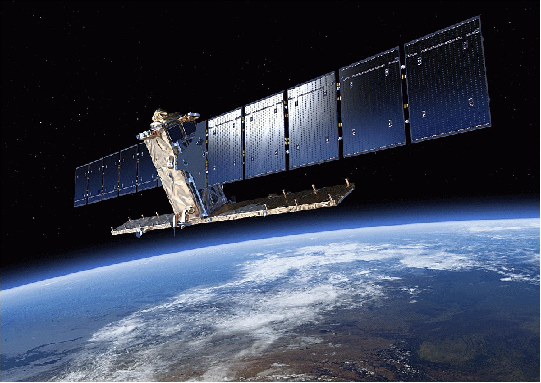
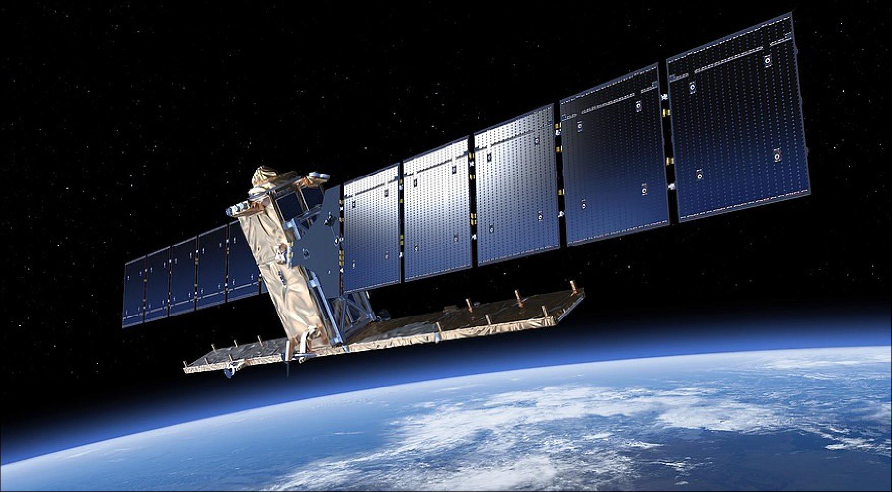
Figure 1: Artist's view of the deployed Sentinel-1 spacecraft (image credit: ESA, TAS-I)
Spacecraft
The spacecraft is based on the PRIMA (Piattaforma Italiana Multi Applicativa) bus of TAS-I, of COSMO-SkyMed and RADARSAT-2 heritage, with a mission-specific payload module. Attitude stabilization: 3-axis, attitude accuracy = 0.01º (each axis), orbital knowledge = 10 m (each axis, 3σ using GPS).
The spacecraft structure provides the accommodation for all platform and payload units. A box type structure has been adopted using external aluminum sandwich material, with a central structure in CFRP (Carbon Fiber Reinforced Plastic). A modular approach has been taken whereby the payload is mounted to a dedicated part of the structure, allowing separate integration & test of the payload before integration to the main part of the structure carrying the platform units. This has many advantages for the overall AIT (Assembly, Integration and Test) process. 15) 16) 17) 18) 19) 20)
The PRIMA platform comprises three main modules, which are structurally and functionally decoupled to allow for a parallel module integration and testing up to the satellite final integration. The modules are: 21)
1) SVM (Service Module), carrying all the bus units apart from the propulsion ones
2) PPM (Propulsion Module), carrying all the propulsion items connected by tubing and connectors
3) PLM (Payload Module), carrying all the payload equipment including the SAR Instrument antenna.
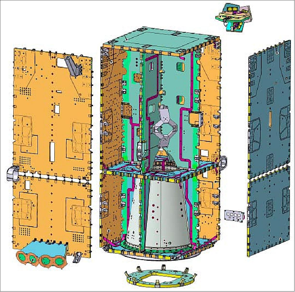
Figure 2: 3D exploded view of the Sentinel-1 platform (image credit: TAS-I)
TCS (Thermal Control Subsystem): The TCS provides control of the thermal characteristics and environment of the Satellite units throughout all phases of the mission. In general the TCS is passive, with the control provided using standard techniques such as heat pipes, radiators and MLI (Multi-Layered Insulation). Survival heaters are provided to prevent units becoming too cold during non-operative phases.
EPS (Electric Power Subsystem): The EPS uses two solar array wings for power generation. Each wing consists of 5 sandwich panels using GaAs triple junction solar cells. The average onboard power is 4.8 kW (EOL), the Li-ion battery has a capacity of 324 Ah. The PCDU (Power Control and Distribution Unit) is designed to provide adequate grounding, bonding & protection for the overall electrical system (e.g. by use of fuses) and must also be integrated into the satellite FDIR concept to ensure that adequate power resources and management are available in the event of on-board failures. Li-Ion battery technology has been selected for the batteries because of the large benefits offered in terms of mass and energy efficiency.
The spacecraft dimensions in stowed configuration are: 3.4 m x 1.3 m x 1.3 m. The Sentinel-1 spacecraft has a launch mass of ~2,200 kg, the design life is 7.25 years (consumables for up to 12 years). 22) 23)
Since the B2 Phase of Sentinel-1, a commonality approach with Sentinel-2 and Sentinel-3 was introduced and deeply investigated, to optimize and minimize as much as possible new developments, HW procurement and operations costs. Besides the differences among payload instruments and their relative required performances, each of these three satellites have its orbital parameters, as well its specific requirements. 24) 25)
Parameter | Sentinel-1 | Sentinel-2 | Sentinel-3 |
Launch date | April 03, 2014 of S1-A | June 23, 2015 of S2-A | 2016 of S3-A |
Orbit type | SSO (Sun-synchronous Orbit) 12 day repeat cycle LTAN = 18:00 hours | SSO 10 day repeat cycle LTDN = 10:30 hours | SSO 27 day repeat cycle LTDN = 10:00 hours |
Orbital altitude | 693 km | 786 km | 814.5 km |
Sensor complement | C-SAR (C-band Synthetic Aperture Radar) | MSI (Multi Spectral Instrument) | SRAL (Sentinel-3 Radar Altimeter) MWR (MicroWave Radiometer) OLCI (Ocean and Land Color Instrument) SLSTR (Sea and Land Surface Temperature Radiometer) |
Spacecraft mass Spacecraft size Spacecraft power | 2300 kg 3.4 m x 1.3 m x 1.3 m 4.8 kW (EOL) | 1140 kg 3.0 m x 1.7 m x 2.2 m 1.7 kW (EOL) | 1250 kg 3.9 m x 2.2 m x 2.2 m 2.05 kW (EOL) |
Downlink X-band data rate | 520 Mbit/s | 520 Mbit/s | 520 Mbit/s |
TT&C S-band | 64 kbit/s uplink 128 kbit/s or 2 Mbit/s downlink | 64 kbit/s uplink 128 kbit/s or 2 Mbit/s downlink | 64 kbit/s uplink 128 kbit/s or 2 Mbit/s downlink |
Science data storage | 1.4 Tbit (EOL) | 2 Tbit (EOL) | 300 Gbit (EOL) |
Required data quality | BER (Bit Error Rate): < 10-9 | FER (Frame Error Rate): < 10-8 | FER (Frame Error Rate): < 10-7 |
Operational autonomy | 8 days | 14 days | 27 days |
Prime contractor | TAS-I (Thales Alenia Space-Italy) | EADS Astrium GmbH, Germany | TAS-F (Thales Alenia Space-France) |
Baseline launcher | Soyuz (Kourou) | Vega (Kourou) | Rockot vehicle of Eurockot Launch Services |
Table 2: List of some Sentinel-1, -2, -3 characteristics and key requirements impacting on end-to-end performance 26)
The Sentinel-1 spacecraft design is characterized by a single C-band SAR (Synthetic Aperture Radar) instrument with selectable dual polarization, a deployable solar array, large on-board science data storage, a very high X-band downlink rate, and stringent requirements on attitude accuracy and data-take timing. In addition, the spacecraft will embark the LCT (Laser Communication Terminal) unit allowing downlink of recorded data via the EDRS (European Data Relay Satellite). 27) 28)
Spacecraft stabilization | 3-axis stabilized |
Attitude accuracy, knowledge | ≤ 0.01º for each axis, < 0.003º for each axis |
Nominal flight attitude, attitude profile | Right side looking geometry, geocentric and geodetic |
Orbit knowledge | 10 m (each axis, 3 sigma) using GPS (dual frequency receiver) |
Operative autonomy of spacecraft | 96 hours |
Spacecraft availability | 0.998 |
Spacecraft structure | Box of aluminum sandwich panels + CFRP central structure |
Spacecraft body dimensions | 3.4 m x 1.3 m x 1.3 m |
Spacecraft envelope dimensions | 3.9 m x 2.6 m x 2.5 m |
Spacecraft launch mass | 2157 kg (inclusive 154 kg of monopropellant fuel) |
Spacecraft design life | 7.25 years (consumables for 12 years) |
EPS (Electric Power Subsystem) | 4800 W average (End-of-Life), GaAs triple junction solar cells, 2 solar array wings, each wing of 5 sandwich panels |
Battery (for eclipse operation) Battery assembly mass | Li-ion technology, capacity = 324 Ah, max discharge power ≥ 1950 W ≤ 130 kg |
Onboard science data storage capacity | 1410 Gbit (End-of-Life) |
S-band TT&C data rates | 4 kbit/s TC (telecommand); 16/128/512 kbit/s TM (programmable) |
X-band science data telemetry rate | 600 Mbit/s |
Propulsion subsystem (orbit maintenance) | Monopropellant hydrazine system, 14 thrusters, 6 (orbit control)+8 (attitude) |
Thermal control | Mainly passive, standard techniques |
AVS (Avionics Subsystem): The AVS performs both Data Handling & Attitude/Orbit Control functions. This is realized through the concept of an integrated control system that performs the control of the platform and payload. The AVS performs all data management & storage functions for the satellite, including TM/TC reception and generation, subsystem & unit monitoring, autonomous switching actions and synchronization. The AVS includes the AOCS processing and the interfaces to the AOCS sensors Star trackers, fine sun sensors, and fine gyroscope and actuators, 4 reaction wheels, 3 torque rods, 14 thrusters, 2 solar array drive mechanism. 29)
The AOCS comprises all means to perform transfer- and on-orbit control maneuvers and to control all necessary satellite attitude and antenna pointing states during all mission phases, starting at separation from the launcher until de-orbiting of the satellite at end of life. This includes the attitude steering of the LEO satellite to provide both yaw and roll steering capability.
At present, a dedicated precise orbit predictor is implemented within the AOCS, in addition to making use of the data uploaded to the payload by the GPS constellation. The AOCS (Attitude and Orbit Control Subsystem) can perform some functions autonomously and it is supported by a very reliable FDIR scheme (Ref. 15). Telecommand data will be received from the TT&C subsystem and will be decoded and deformatted in the AVS.
AOCS consists of the following sensors and actuators: fine sun sensors, magnetometers, gyroscopes, star trackers, GPS receivers, magnetic torquers, a reaction wheels assembly and a monopropellant (hydrazine) propulsion system. The propulsion system has 3 pairs of 1 N orbit control thrusters and 4 pairs of reaction control thrusters for attitude correction. Every pair is made up of a prime and a redundant component.
The attitude control thrusters are fired when the spacecraft enters RDM (Rate Damping Mode) after separation, damping any residual rotation left by the launcher upper stage and achieving a spacecraft pitch rotation of -8 times the orbital period. In the subsequent AOCS mode, called SHM (Safe Hold Mode), magnetotorquers and reaction wheels maintain the attitude and reduce the pitch rotation rate to twice the orbital period.
The periodic behavior of the Earth’s magnetic field in a polar orbit and the polarization of the angular momentum with the loading of the reaction wheels allow the magnetotorquers to maintain this pitch rate while aligning the spacecraft –Y axis with the orbit normal, which in a dusk-dawn orbit coincides with the direction to the Sun (Figure 3).
When the appendages deployment commences, the effect of the gravity gradient torque dominates over the magnetic torque, resulting in the alignment of the S/C X axis (appendages axis) with the nadir direction, maintaining thus a pitch rate equal to the orbital period. Upon ground telecommand, a transition into the NPM (Normal Pointing Mode) occurs, where the spacecraft performs a fine attitude control based on the use of reaction wheels in close loop with star trackers, gyroscopes and GPS, and magnetotorquers for wheel unloading (Ref. 20).
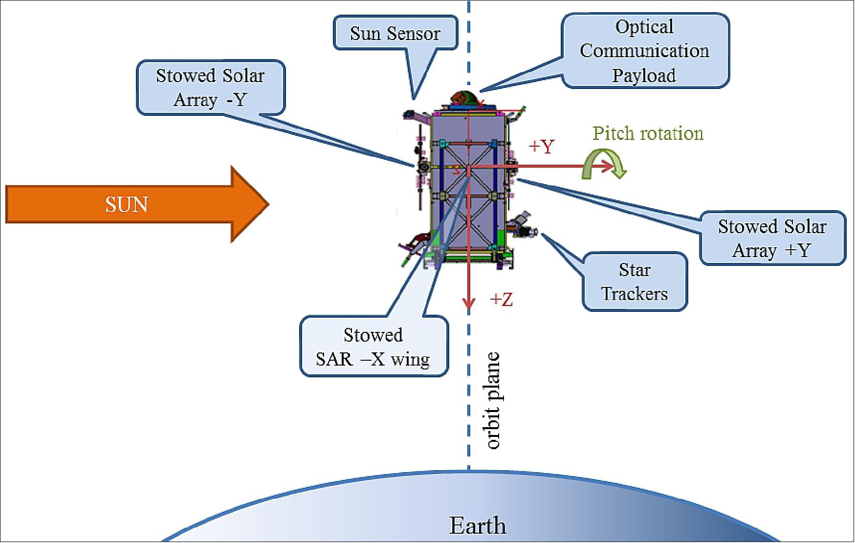
Figure 3: Sentinel-1A stowed representation (in RDM and SHM). +X S/C axis points towards the flight direction. S/C Y axis is aligned with the Sun direction. Solar Array –Y illuminated when stowed (image credit: ESA, Ref. 20)
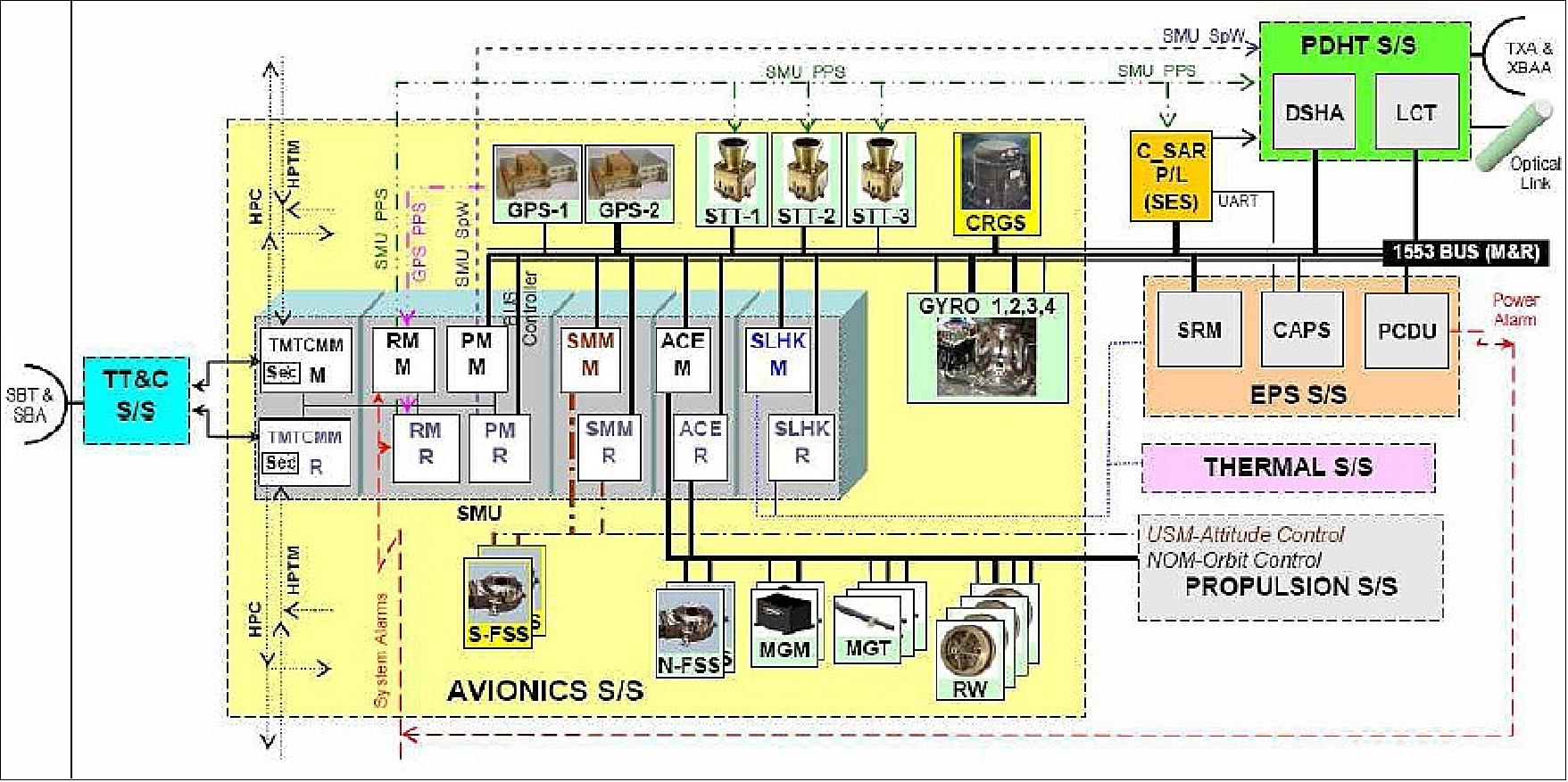
Figure 4: Architecture of the avionics subsystem (image credit: TAS-I)
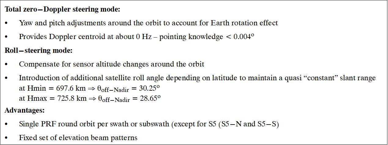
Table 4: Sentinel-1 attitude steering modes (Ref. 97)
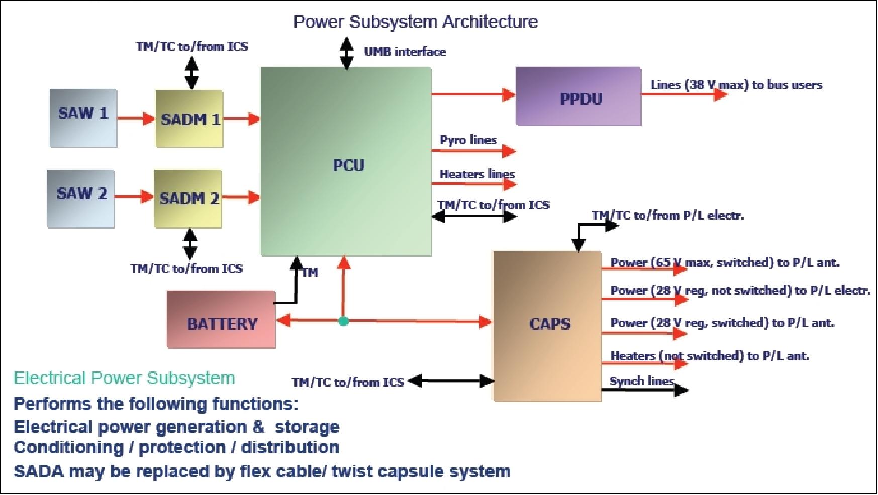
Figure 5: Spacecraft power generation and distribution (image credit: TAS-I)
PDHT (Payload Data Handling & Transmission) subsystem (Ref. 24):
The commonality process is driving the spacecraft design with the objective to satisfy the needs of three different missions within the same product. This involves several Sentinels subsystems, in particular, TAS-I was selected to coordinate the common design of two assemblies: 30)
• TXA (Telemetry X-band transmission Assembly) 31)
• XBAA (X-Band Antenna Assembly)
The objective of the PDHT subsystem is to provide the services of data acquisition, storage and transmission to the ground in X-band. After having acquired observation data from the DSHA (Data Storage and Handling Assembly), the TXA executes encoding, modulation, up-conversion, amplification and filtering; the X-band signal provided at the TXA output is then transmitted by an isoflux, wide coverage antenna, included in the XBAA.
To summarize, the performance requirements on TXA specification took into account the different needs of the Sentinels, allowing a fully recurrent units approach: beside a specific TXA layout due to accommodation needs, the modulator, TWTA, and RF filter are the same for the three Sentinels.
After the selection of the TXA & XBAA suppliers (TAS-España and TAS-I IUEL respectively), an agreement was reached between ESA and the Sentinel prime contractors on the way to handle the common design and procurement for TXA and XBAA.
Besides strong efforts to manage different needs coming from different missions, the commonality activities performed in the frame of Copernicus Sentinels enable an effective optimization of costs and development time for those subsystems selected for a common design.
To provide flexibility in the downlink operation, the PDHT is designed with two X-band independent links. The PDHT provides an overall input/output throughput of about 1950 Mbit/s, with a payload input data rate of 2 x 640 Mbit/s (multi-polarization acquisition) or 1 x 1280 Mbit/s (single-polarization acquisition) and a transmitted symbol rate of 2 x 112 Msample/s. The data storage capacity is > 1410 Gbit at EOL.
The provided antenna isoflux coverage zone is about ±64º to nadir to allow link establishment with the ground starting from the ground antenna elevation angle of 5º above the horizon.
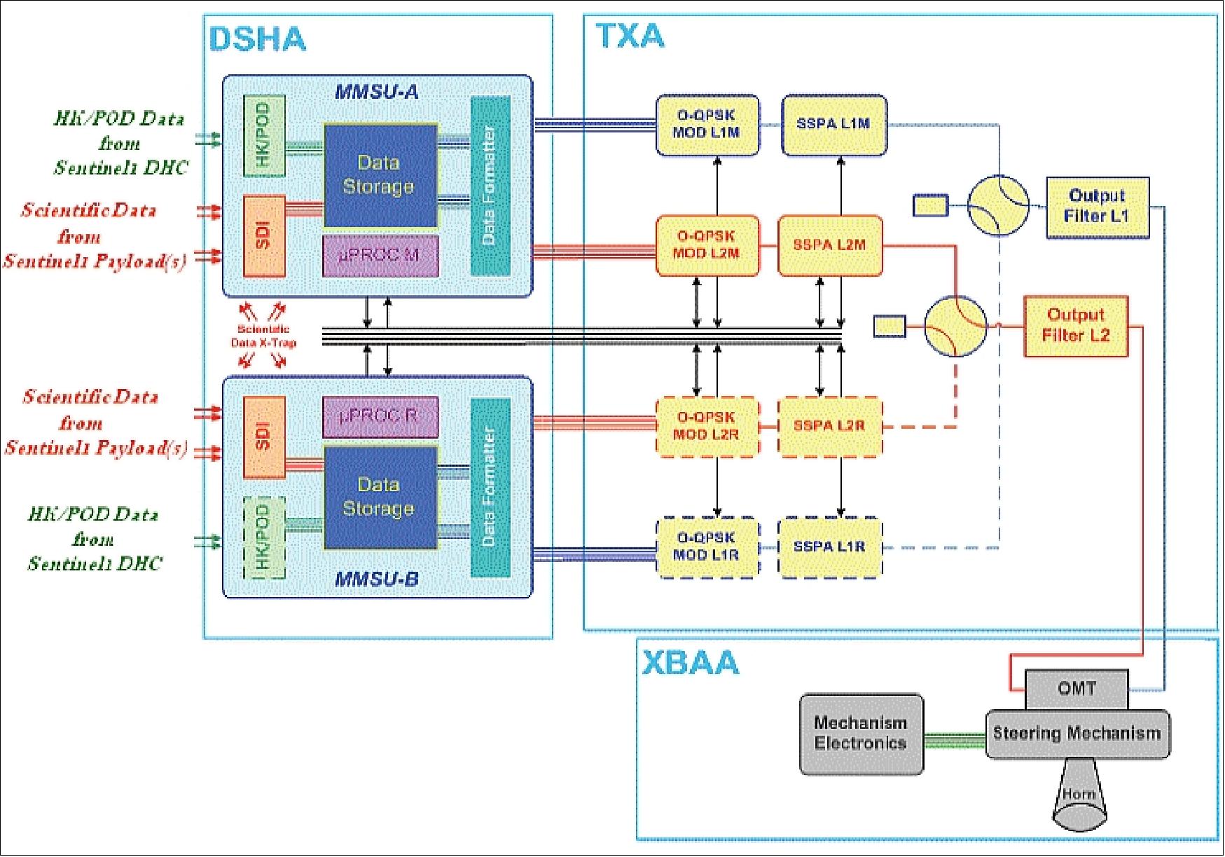
Figure 6: The PDHT (Payload Data Handling & Transmission) subsystem (image credit: TAS-I)
Legend of Figure 6:
• DSHA (Data Storage & Handling Assembly)
• TXA (Telemetry X-band transmission Assembly)
• XBAA (X-band Antenna Assembly)
Mass memory capacity of SAR data (EOL) | > 1400 Gbit (SD-RAM based cubes) |
Mass memory capacity of HK/GNSS/POD data (EOL) | 32 Gbit |
PDHT overall throughput | 1950 Mbit/s |
Encryption | AES (Advanced Encryption Standard) |
Coding | RS (255,223) |
Information data rate (on each link) | 300 Mbit/s |
Bandwidth (on each link, without baseband shaping) | 280 MHz |
Modulation scheme | O-QPSK |
Frequency carrier | 8180 MHz |
EIRP (on each channel) | > 18.45 dBW |
Antenna gain (at 4.5º w.r.t. boresight) | > 20 dB |
Polarization | RHCP and LHCP |
Antenna pointing mechanism speed | 2º/s |
Maximum power consumption (10% of contingency) | 450 W |
Table 5: Main performance characteristics of the PDHT
The TXA architecture provides two redundant X-band channels with the same output power (16 dBW) and useful data rate (260 Mbit/s). Cold redundancy is implemented at channel level. The main elements of the assembly are:
- X-band modulators, developed by TAS-F, are fully compliant with ECSS and modulation standard
- TWTA (Traveling Wave Tube Amplifiers), provided by TAS-B (ETCA), deliver up to 60 W RF power
- OMUX (Optical Multiplexer), developed by TAS-F, filters and combines both channels and provides out of band rejection.
To achieve good spectral confinement and especially to ensure that the emission levels in the adjacent deep space band (8400 to 8450 MHz) are respected, both baseband filtering with a roll-off of 0.35 (0.35-SRRC) and filtering techniques have been applied. In addition, 6-pole channel band pass filters have been implemented in the OMUX. The 6-pole solution provides two main advantages in front of other less selective solutions, such as 4-pole:
- It filters our more efficiently the regrowth of baseband filtered 8PSK carrier due to the gain nonlinearity of the TWTA, thus allowing for a better overall DC efficiency
- It is compatible with data rates up to 300 Mbit/s per channel by adjusting the frequency plan (increase of frequency spacing between channels).
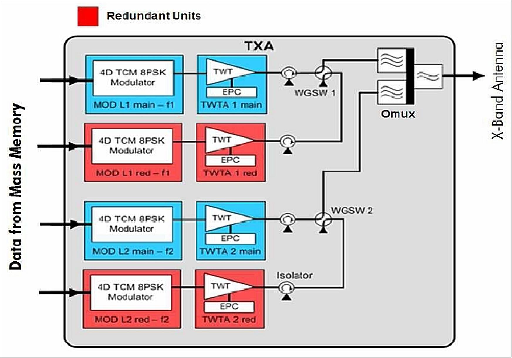
Figure 7: Architecture of the TXA (image credit: TAS)
Parameter | Performance | Remarks |
Frequency plan | F1 = 8095 MHz, F2 = 8260 MHz |
|
Occupied bandwidth | < 295 -2.1/+1.8 MHz for 112 MS/s | < 130 MHz per channel |
Modulation scheme | 8PSK |
|
Inner coding | TCM 5/6 encoding rate |
|
Downlink useful data rate | 280 Mbit/s per channel at modulator input | 260 Mbit/s channel at RS decoder output |
RF losses | < 1.1 dB | Between TWTA output and TXA output I/F |
RF output power level | > 15.3 dBW per channel | At OMUX output flange |
Transmission technological degradation (at FER <10-7) | < 1.4 dB | Both channels active |
Power consumption, dissipation | < 280 W, < 195 W | Both channels active |
Mass of device | < 24.7 kg | Panel excluded |
PRP (Propulsion Subsystem): The PRP is based on 14 RCTs (Reaction Control Thrusters) located in 4 different sides of the spacecraft, provides the means to make orbit corrections to maintain the requested tight orbit control throughout the mission. Initially, corrections are required to reach the final orbit position after separation from the launcher. During the mission, some infrequent corrections to the orbit are necessary to maintain the requirements upon the relative and absolute positioning of individual satellite. The thrusters located on the –Z side of the satellite are specifically dedicated to attitude control during the safe mode.
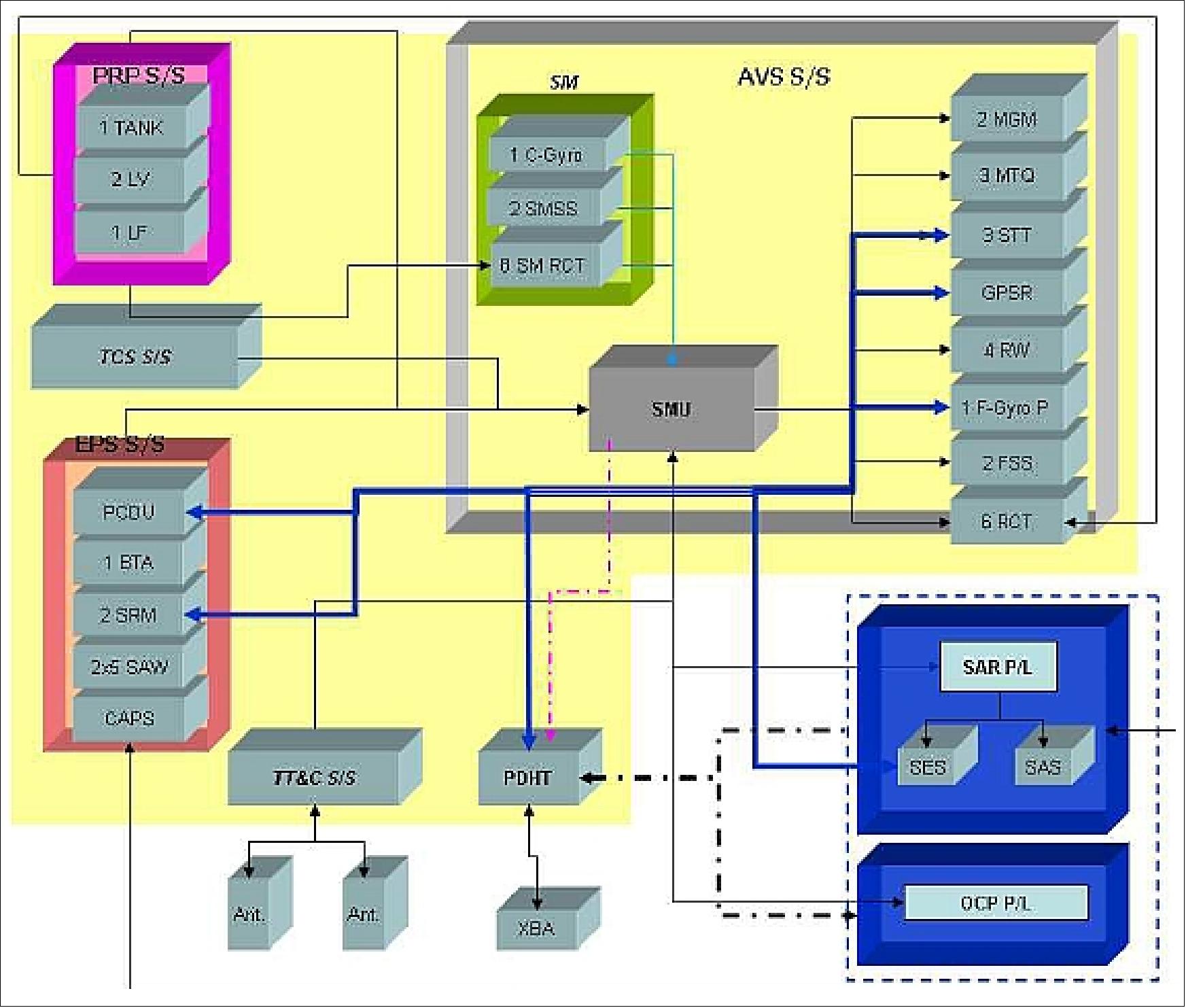
Figure 8: Sentinel-1 satellite block diagram (TAS-I, ESA, Ref. 15)
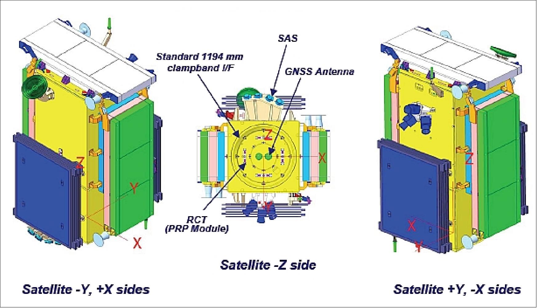
Figure 9: Stowed satellite views (image credit: TAS-I)
RF communications: Onboard source data storage volume of 900 Gbit (EOL). TT&C communications in S-band at 4 kbit/s in uplink and 16, 128, or 512 kbit/s in downlink (programmable). Payload downlink in X-band at a data rate of 2 x 260 Mbit/s.
The Copernicus Sentinel spacecraft are the first ESA Earth Observation spacecraft to implement communications security on the command link. It has been decided to secure the spacecraft from unauthorised command access by adding a security trailer to the command segments which are sent to the spacecraft. The trailer is composed of a Logical Authentication Counter and a Message Authentication Code. The latter is obtained by performing cryptographic encryption of the hash value of the command segment and the Logical Authentication Counter. Only parties in possession of the right key can perform this operation in a way that the command segment is accepted by the spacecraft. The concept applies to all Copernicus Sentinel spacecraft. 32)
Science data compression: Currently, the most promising solution seems to be the FDBAQ (Flexible Dynamic Block Adaptive Quantization) approach as proposed by ESA; 3 output bits would be sufficient for most of “typical” acquisitions over various targets, while few high reflectivity scenes would need 4 bits, making the expected average output bit rate little higher then 3 bits, thus lower then the estimated 3.7 bits for the ECBAQ (Entropy-Constrained Block Adaptive Quantization) compression. 33) 34) 35) 36)
Data delivery: Sentinel-1 will provide a high level of service reliability with near-realtime delivery of data within 1 hour after reception by the ground station, and with data delivery from archive within 24 hours.
OCP (Optical Communication Payload): In parallel to the RF communications, an optical LEO-GEO communications link using the LCT (Laser Communication Terminal) of Tesat-Spacecom (Backnang, Germany) will be provided on the Sentinel spacecraft. The LCT is based on a heritage design (TerraSAR-X) with a transmit power of 2.2 W and a telescope of 135 mm aperture to meet the requirement of the larger link distance. The GEO LCT will be accommodated on AlphaSat of ESA/industry (launch 2012) and later on the EDRS (European Data Relay Satellite) system of ESA. The GEO relay consists of an optical 2.8 Gbit/s (1.8 Gbit/s user data) communication link from the LEO to the GEO satellite and a 600 Mbit/s Ka-band communication link from the GEO satellite to the ground. 37)
Since the Ka-band downlink is the bottleneck for the whole GEO relay system, an optical ground station for a 5.625 Gbit/s LEO-to-ground and a 2.8 Gbit/s GEO-to-ground communication link is under development.
LCT | 1st Generation | 2nd Generation | 3rd Generation |
Link type | LEO-LEO | LEO-GEO | LEO-LEO, LEO-GEO, UAS-GEO |
Mission | NFIRE, TerraSAR-X | Sentinel 1 & 2, AlphaSat, ERDS | Euro Hawk, Global Hawk |
Lifetime | 2-5 years | 15 years | Mission depending |
Data rate | 5.625 Gbit/s | 1.800 Gbit/s | 1.800 - 5.625 Gbit/s |
Range | 1000 - 5100 km | < 45,000 km | 1000 - 45,000 km |
Target BER | 1 x 10⁻⁸ | 1 x 10⁻⁸ | Better than 1 x 10⁻⁸ |
Tx power | 0.7 W | 2.2-5.0 W | < 5 W |
Telescope diameter | 125 mm | 135 mm | < 125 mm |
Instrument mass | ~33 kg | ~53 kg | < 45 kg |
Power consumption | ~ 120 W | ~160 W | 120 - 180 W |
Instrument volume | ~ 0.5 m x 0.5 m x 0.6 m | ~ 0.6 m x 0.6 m x 0.74 m | 3-box design (TBD) |
Technology Readiness Level | TRL9 | TRL5 | TBD |
Table 7: Technical data of the LCT generations 38)
Ground segment: Spacecraft operations is provided by ESOC, Darmstadt, while the payload data processing and archiving functions (including the planning for SAR data acquisitions) are provided by ESRIN, Frascati. Options are being provided to permit some functions to be outscored to other operating entities.
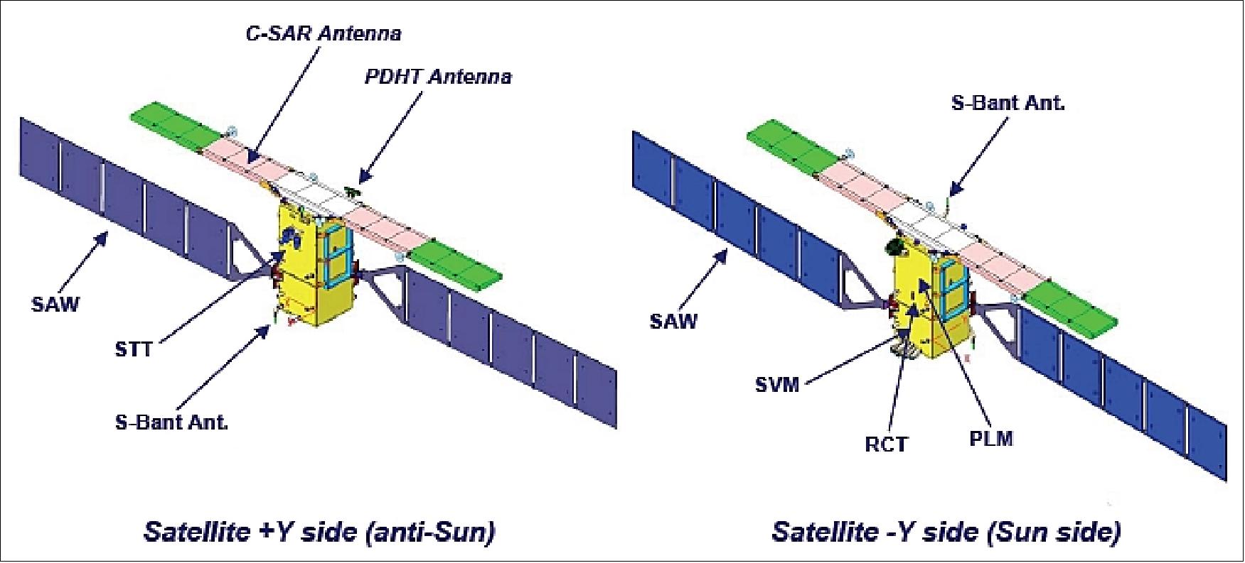
Figure 10: Isometric views of the deployed satellite (image credit: TAS-I)
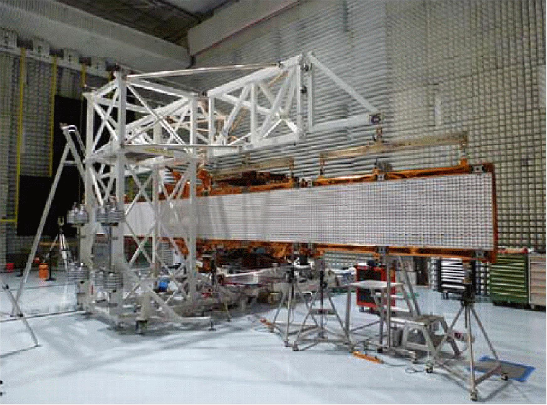
Figure 11: SAR antenna deployment test supported by zero gravity deployment device (solar array in stowed position), image credit: TAS-I, (Ref. 21)
Figure 12 shows the fully integrated Sentinel-1A spacecraft with the SAR antenna and the solar array wings in stowed position. The figure shows the Sentinel-1 spacecraft already mounted on the shaker and ready for sine vibration testing after it has successfully passed the Mass Properties measurements (namely center of mass and inertia moments). Successful completion of vibration and acoustic testing has been followed by the deployment tests of both the SAR antenna and the solar array. Each solar array is tied down on four hold down points by dedicated Kevlar cables. Wing deployment is purely passive, driven by springs, and actuated upon activation of specific thermal knives devices. The time to complete deployment of one wing lasts about 3.5 minutes since the last cable cut. In the end position, the solar array panels are mechanically latched.
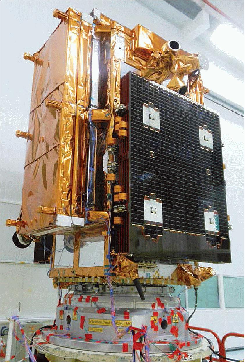
Figure 12: Photo of the Sentinel-1A spacecraft during functional tests in Cannes, France (image credit: TAS) 39)
• Before shipment to the launch site in late February 2014, the Sentinel-1 spacecraft has spent the last couple of months at Thales Alenia Space in Cannes, France, being put through a last set of stringent tests. This included suspending the satellite from a structure to simulate weightlessness and carefully unfolding the two 10 m-long solar wings and the 12 m-long radar antenna. 40)
• The first satellite dedicated to Europe’s Copernicus environmental monitoring program arrived at Cayenne in French Guiana on 24 February 2014. Sentinel-1A is scheduled to be launched from Europe’s spaceport in Kourou on 3 April. By delivering timely information for numerous operational services, from monitoring ice in polar oceans to tracking land subsidence, Sentinel-1 is set to play a vital role in the largest civil Earth observation programme ever conceived. 41)
Launches
Launch of S-1A: The Sentinel-1A spacecraft was launched on April 3, 2014 (21:02 UTC) on a Soyuz-STB Fregat vehicle from Kourou, French Guiana (the launch is designated as VS07 by the launch provider Arianespace). After a 617 second burn, the Fregat upper stage delivered Sentinel-1A into a Sun-synchronous orbit at 693 km altitude. The satellite separated from the upper stage 23 min 24 sec after liftoff. 43)
Launch of S-1B: The Sentinel-1B spacecraft, a twin sister of Sentinel-1A, was launched on April 25, 2016 (21:02:13 GMT) into the same orbital plane of Sentinel-1A (phased by 180º). The launcher was a Soyuz-STA/Fregat vehicle (VS 14) of Arianespace and the launch site was Kourou. 44) 45)
The contract between ESA and Arianespace to launch the Sentinel-1B satellite was signed on July 17, 2014 by ESA’s Director of Earth Observation Programs, Volker Liebig, and CEO of Arianespace, Stéphane Israël, at ESA headquarters in Paris, France. As part of the Copernicus program, Sentinel-1B will round out the initial capacity offered by Sentinel-1A to offer a comprehensive response to the need for environmental and security monitoring via spaceborne radar systems. 46) 47) 48)
On March 22, 2016, the Sentinel-1B satellite has arrived in French Guiana to be prepared for liftoff on 22 April. 49)
Secondary payloads of Sentinel-1B: 50)
• MicroSCOPE, a minisatellite (303 kg) of CNES (French Space Agency) which will test the universality of free fall (equivalence principle for inertial and gravitational mass as stated by Albert Einstein).
• AAUSAT4, a 1U CubeSat of the University of Aalborg, Denmark to demonstrate an AIS (Automatic Identification System), identifying and locating ships sailing offshore in coastal regions.
• e-st@r-II (Educational SaTellite @ politecnico di toRino-II), a 1U CubeSat from the Polytechnic of Turin, Italy.
• OUFTI-1 (Orbital Utility for Telecommunication Innovation), a 1U CubeSat of the University of Liège, Belgium, a demonstrator for the D-STAR communications protocol.
Tyvak International installed the three CubeSats in the orbital deployer. The three CubeSats are part of ESA's FYS (Fly Your Satellite) student program.
Orbit: Sun-synchronous near-circular dawn-dusk orbit, altitude = 693 km, inclination = 98.18º, orbital period = 98.6 minutes, ground track repeat cycle = 12 days (175 orbits/cycle). An exact repeat cycle is needed for InSAR (Interferometric Synthetic Aperture Radar) support. LTAN (Local Time on Ascending Node) = 18:00 hours.
Orbital tube: A stringent orbit control is required to the Sentinel-1 system. Satellites’ position along the orbit needs to be very accurate, in terms of both accuracy and knowledge, together with pointing and timing/synchronization between interferometric pairs. Orbit positioning control for Sentinel-1 is defined by way of an orbital Earth fixed “tube” 50 m (rms) wide in radius around a nominal operational path (Figure 14). The satellite is kept inside such a tube for most of its operational lifetime Ref. 15). 51)
One of the challenges of the Sentinel-1 orbit control strategy is the translation of a statistical tube definition in a deterministic control strategy practically functional to the ESOC (European Space Operations Center) operations.
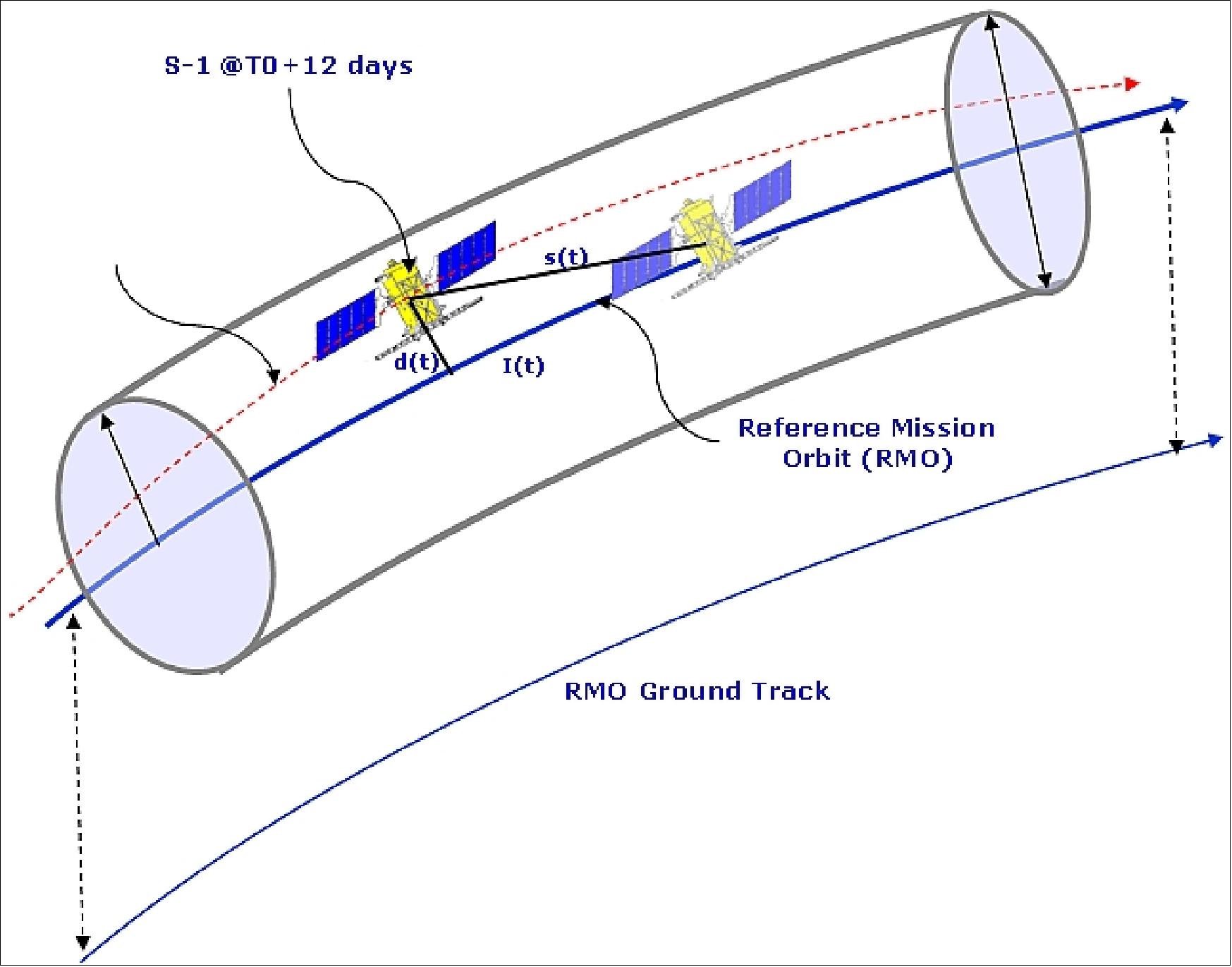
Figure 14: Schematic view of the orbital tube (image credit: ESA, TAS, Ref. 15) 52)
The second obvious challenge is the very stringent tube diameter which forces the application of frequent and intense maneuvers nevertheless still compatible with S/C request for consumables of up to a 12 years lifetime.
A satellite control strategy has been specifically developed and consists in applying a strict cross-track dead-band control in the most Northern Point and in the ascending node crossing. Controlling the orbit at these 2 latitudes, the satellite is shown to remain in the tube, within the rms (root mean square) criteria, for all other latitudes.
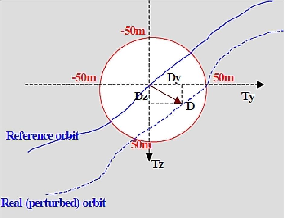
Figure 15: Orbital tube section (image credit: ESA, TAS, Ref. 15)
Orbit knowledge accuracy (< 3 m rms in each axis) in realtime for autonomous operations is not considered as demanding as the on-ground postprocessing requirements (< 5 cm 3D rms) for the detection of (slow) land movements and deformations through the differential interferometry technique. The latter is almost as demanding as for Sentinel-3 and requires dual-frequency receivers. 53)
As both satellites, Sentinel-1A and Sentinel-1B, will fly in the in the same orbital plane with 180º phased in orbit, and each having a 12-day repeat orbit cycle, it will facilitate the formation of SAR interferometry (InSAR) image pairs (i.e., interferograms) having time intervals of 6 days. This, along with the fact that the orbital deviation of each Sentinel-1 satellite will be maintained within a tube of ±50 m radius (rms) will enable the generation of geographically comprehensive maps of surface change such as for measuring ice velocity in the Polar regions, as well as monitoring geohazard related surface deformation caused by tectonic processes, volcanic activities, landslides, and subsidence (Ref. 119).
Launch of S-1C: The launch of Sentinel-1C is now scheduled for March 2024, following a delay due to a launch failure of Vega-C in December 2022. 158) 159)
As of 9 February 2022, the Sentinel-1 article has been split into four parts.
• Sentinel-1 mission and its imagery in the period 2020
• Sentinel-1 mission and its imagery in the period 2019
• Sentinel-1 imagery in the period 2018-2014
Mission Status
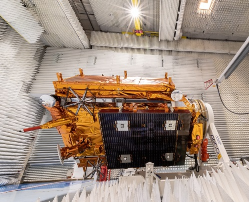
• February 22, 2023: Europe’s next synthetic aperture radar satellite, Copernicus Sentinel-1C, has undergone pre-flight testing at Thales Alenia Space’s facility in Cannes, France. Those tests include ensuring the satellite will survive the noise and vibrations it will experience during launch and separation from the rocket.
The mechanisms that will deploy the satellite’s two 10-metre-long solar panel wings and 12-metre-long radar antenna have also been tested. There have also been electromagnetic and radio frequency compatibility tests.
Sentinel-1C will soon be moved from Cannes to Rome for short-term storage before being sent to the launch site in French Guiana. 157)
• August 3, 2022: The European Space Agency and the European Commission announce the end of the mission for the Copernicus Sentinel-1B satellite and regret the inconvenience caused to the Copernicus Services, Copernicus Participating States, and the many users worldwide affected by the lack of Sentinel-1B data. The conclusions drawn by the Anomaly Review Board resulted in the impossibility to recover the 28V regulated bus of the C-SAR Antenna Power Supply unit (CAPS), which provides power to the radar electronics. The capability of Sentinel-1B to support the mission is therefore considered lost. A summary report of the description of the anomaly, of the investigations and the recovery attempts, as well as the parallel Sentinel-1 mission level actions and way forward is available here. 155)
Copernicus Sentinel-1A remains fully operational. Efforts have been deployed to launch Sentinel-1C as early as possible,the plan was to launch in the second quarter of 2023. However, there have been no further updates to this projection. The successful VEGA-C maiden flight on 13 July 2022 marks a major milestone towards the launch of Sentinel-1C. The start of the Sentinel-1B disposal is planned to take place after the Sentinel-1C In-Orbit Commissioning Review (IOCR), indicatively during the third quarter of 2023. The de-orbiting activities will last several months (current estimate in the order of 9 months). 156)
• July 26, 2022: Any movement beneath our feet – from barely perceptible subsidence to the sudden appearance of a sinkhole or a crashing landslide – spells big trouble. Even relatively modest subsidence can weaken buildings and infrastructure and lead to issues such as flooding, and at worst the abrupt disappearance of sections of land brings immediate threat to life. Monitoring and predicting our shifting land is essential for adopting mitigating strategies. 58)
- The new European Ground Motion Service, the latest offering of the Copernicus Land Monitoring Service and implemented by the European Environment Agency, provides free and accessible ground motion data to anyone who wishes to use it. Based on radar data from Copernicus Sentinel-1 satellite mission, the service provides information on the motion of land, structures and infrastructure in Copernicus Participating States. It aims to give users reliable information on ground motion at a local, regional or national scale. The ‘radar interferometry’ remote sensing technique combines two or more radar images from the same orbital geometry over the same area to detect changes occurring between acquisitions. Interferometry allows for the monitoring of even slight ground movement – down to a few millimetres – across wide areas. Using these millimetre-scale measurements of ground motion, the European Ground Motion Service enables the mapping of subsidence and landslides, as well ground affected by seismic and tectonic activity. The European Ground Motion Service, which provides data on a continental scale, in the form of maps colour-coded by the velocity of ground motion, in terms of millimetres per year. The measurements provided by the European Ground Motion Service are valuable for many user communities.
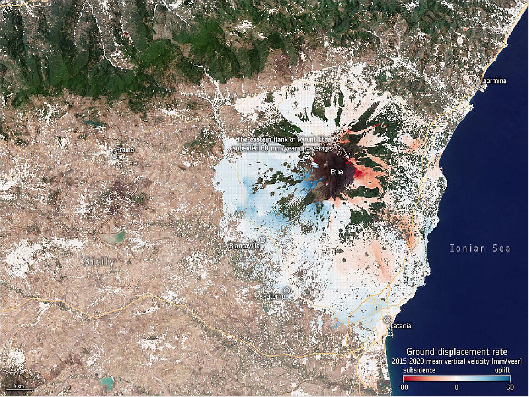
- The images here are examples of data that can be accessed through the service. They depict ground motion around Mount Etna and Bologna in Italy, as well as an area around Larissa in Greece. This new service, which was initiated by the European Union as part of the Copernicus programme, is also closely linked with other aspects of ESA’s Earth Observation Programmes such as the Geohazards Exploitation Platform. This is a research and development processing environment dedicated to terrain motion mapping that has been upgraded to allow for the visualisation of products delivered by the European Ground Motion Service. It offers further interferometric processing with complementary on-demand processing such as the SNAPPING service and the P-SBAS service that use Sentinel-1 time series. Accessing the European Ground Motion Service on the Geohazards Exploitation Platform and combining it with complementary processing chains is intended to maximise the impact and benefit of the technology with user communities. Beyond this, the availability of the European Ground Motion Service is intended to help increase awareness and acceptance of radar interferometry as a solution in various industry sectors on a global basis where service providers from Europe have commercial Earth observation-based capabilities using both Sentinel-1 synthetic aperture radar and very high-resolution synthetic aperture radar missions. The European Ground Motion Service is available to the public, everyone can register on the platform and access the data.
• June 30, 2022: Bangladesh is no stranger to heavy rain, but this year the northeast region is being subjected to the highest rainfall it has seen in more than a century. Days of heavy rain at the beginning of monsoon season have caused widespread flooding, leaving millions stranded and vast areas affected. This flooding has come shortly after a pre-monsoon flood that badly affected the same region a month ago. 59) The services take advantage of observations from several satellites and provide on-demand mapping to help civil protection authorities and the international humanitarian community in the face of major emergencies.

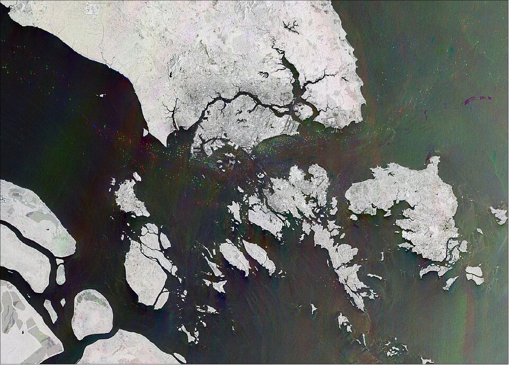
• June 10, 2022: The Republic of Singapore is located just off the southern tip of the Malayan Peninsula, between Malaysia and Indonesia, around 135 km north of the equator. It consists of the 710 km2 Singapore Island, visible in the top-centre of the image, as well as some 60 small islets. That week’s image contains satellite data stitched together from three separate radar scans, to detect changes occurring between acquisitions. The sea surface reflects the radar signal away from the satellite, making water appear dark in the image and contrasts with metal objects, in this case ships and vessels, which appear as bright, sparkly dots in the dark water. The advantage of radar as a remote sensing tool is that it can image Earth’s surface through rain and cloud, and regardless of whether it is day or night. This is particularly useful for monitoring areas prone to long periods of darkness – such as the Arctic – or providing imagery for emergency response during extreme weather conditions.
• May 26, 2022: The effects of our warming climate are seen across a multitude of measures, usually as incremental changes: more frequent extreme weather, heatwaves, droughts and wildfires. The cumulative impact of these changes, however, can cause fundamental parts of the Earth system to change more quickly and drastically. These ‘tipping points’ are thresholds where a tiny change pushes the system into an entirely new state. 60 . At the ESA’s Living Planet Symposium, scientists came together to discuss the latest research evidence for climate tipping points and identify the opportunities and challenges of using remote sensing data to understand them.
- Tipping points are typically self-propelling, so that, once triggered, they drive deeper change. The global view and high spatial resolution afforded by satellites pose a particularly useful opportunity, said researchers at ESA’s Living Planet Symposium in Bonn, Germany. Remote sensing has already been used to provide critical evidence of the proximity of several tipping elements, ranging from ice sheets to boreal and tropical forests. The recently published IPCC sixth climate Assessment Report warns that high impact climate tipping points at regional scales cannot be ruled out. The risk of crossing thresholds into more abrupt changes increases at higher levels of global warming.
- The discussion follows on from an ESA workshop held in 2021 that considered how Earth observations can be used for monitoring and early warning of tipping points, hosted by the International Space Science Institute with the Future Earth ‘AIMES’ project and the World Climate Research Programme. Key areas under discussion included how to develop systems for early warning of tipping onset and using remote sensing to examine the interactions between tipping elements.
• April 7, 2022: ESA on behalf of the European Commission, and Arianespace have signed a launch contract for the third radar satellite in the Sentinel-1 mission, Sentinel-1C. 55) 56)
- The launch is scheduled in the first half of 2023 from the Guiana Space Center, Europe’s Spaceport in French Guiana. Sentinel-1C is part of Copernicus, a joint European Union and European Space Agency (ESA) Earth Observation program. The satellite with a mass of 2.3 tons will be placed in a Sun-synchronous orbit with an altitude around 690 km.
- “We are very proud of this new launch contract for the European Commission and the European Space Agency; it underlines our long-standing partnership for the success of Copernicus”, said Stéphane Israël, CEO of Arianespace. “For Arianespace, this contract is a sign of the confidence in the Vega-C system and a strong sign of the commitment of European institutions for an autonomous access to space”.
- Before Sentinel-1C satellite, both Sentinel-1A and -1B were previously launched with Arianespace in 2014 and 2016. Sentinel-1C will round out the initial capacity offered by the two preceding satellites to offer a comprehensive response to the needs for environmental and security monitoring via spaceborne radar systems. Sentinel satellites are part of the Copernicus program designed to give Europe continuous, independent and reliable access to Earth observation data.
- ESA’s new Vega-C launcher, built by Avio (Colleferro, Italy) as prime contractor, has been specifically upgraded to launch satellites of the class of Sentinel-1C and it is perfectly suited to serve the Earth Observation market because of its performance and versatility.
- According to Ref. 56), Sentinel-1B is currently unavailable due to a technical anomaly, so it is important to get Sentinel-1C into orbit and operational as soon as possible.
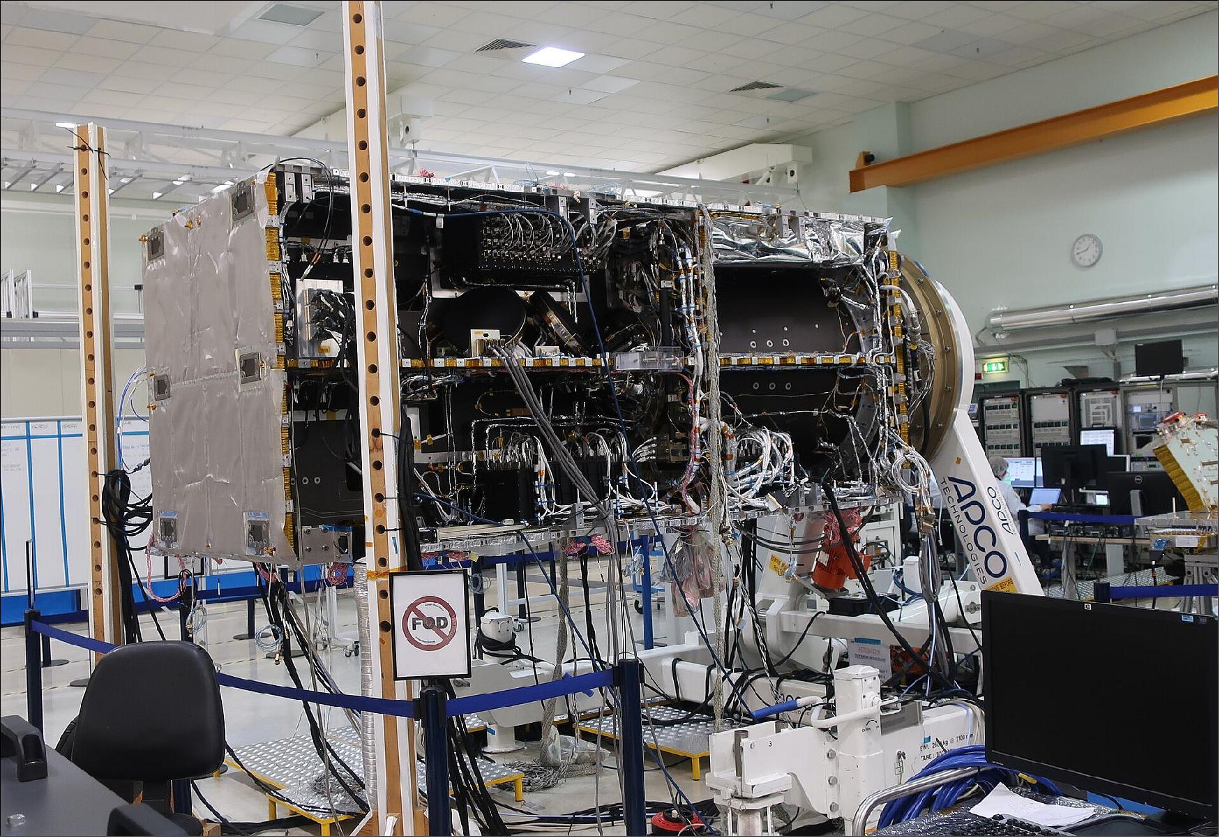
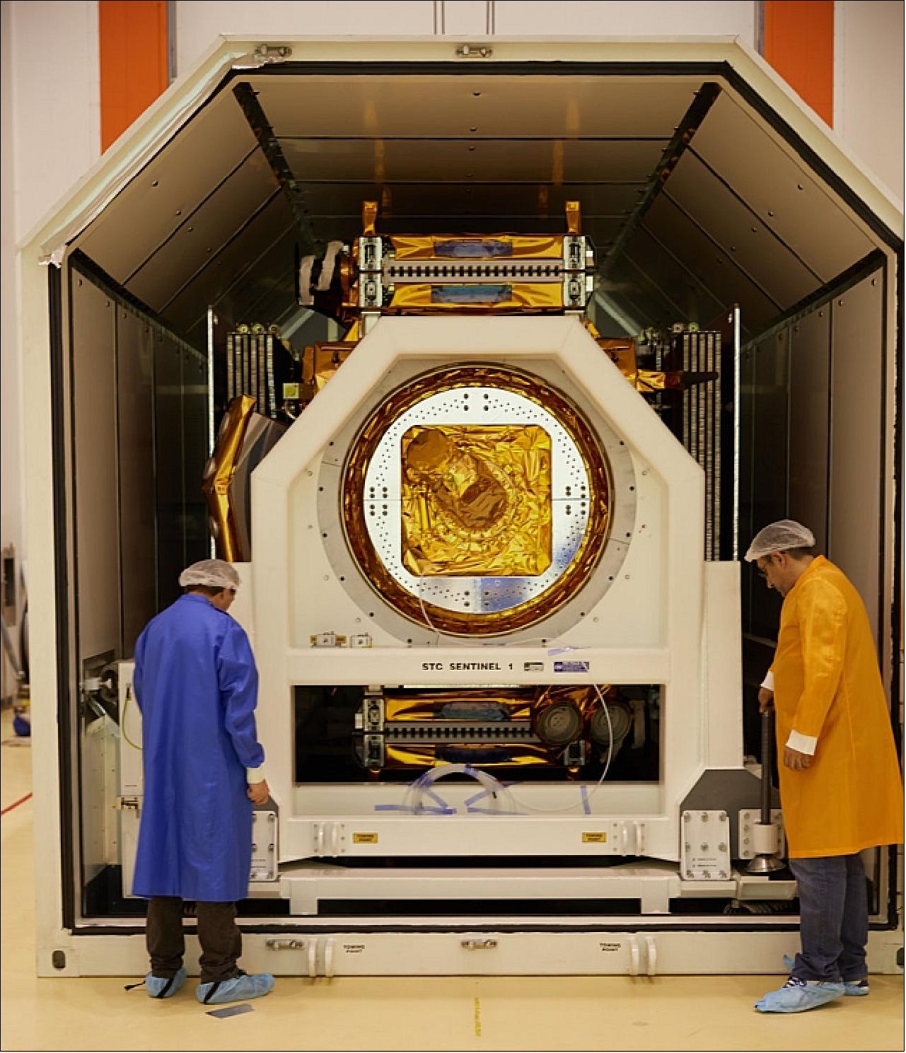
Figure 23: Copernicus Sentinel-1C in testing. The image shows the satellite during integrated system tests before being prepared for thermal vacuum tests (Ref. 56)
• March 21, 2022: European Space Agency officials said prospects are dimming for the recovery of a radar imaging satellite that malfunctioned nearly three months ago, but that efforts to save the spacecraft continue. 61) The Sentinel-1B spacecraft malfunctioned in December, keeping the spacecraft from collecting C-band synthetic aperture radar (SAR) imagery. ESA said in January that they were investigating a problem with the power system for the SAR payload on the satellite, launched in April 2016. In a February 25th update, the ESA said work was continuing to investigate problems with both the main and backup power system for the payload but that effort had yet to identify a root cause of the anomaly. The problem doesn’t affect operations of the spacecraft itself, which has remained under control. ESA leaders were not optimistic about the prospects of recovering Sentinel-1B.
- The ESA floated the possibility of moving up the launch of a new SAR satellite, Sentinel-1C, to compensate for the potential loss of Sentinel-1B. The mission currently is scheduled for launch in the middle of 2023 although the spacecraft would be ready for launch after a flight acceptance review scheduled for October. They confirmed that Sentinel-1C would be ready for launch in October but the ESA had not yet decided if the launch could be moved up. A problem for any effort to move up the Sentinel-1C launch was the Russian decision to halt Soyuz launches from French Guiana, requiring five European missions that planned to fly on that rocket there to look for alternative vehicles.
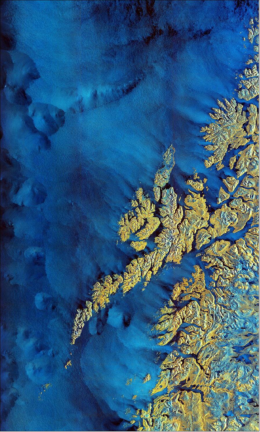
• March 11, 2022: The Copernicus Sentinel-1 mission takes us over the archipelago of Lofoten in northern Norway. 63) Extending around 175 km from north to south, the archipelago comprises five main islands (Austvågøya, Gimsøya, Vestvågøya, Flakstadøya, and Moskenesøya), as well as many small islands and skerries (rocky islets and reefs). Sentinel-1 is a radar mission and unlike optical cameras, the images are usually black and white when they are received. By using a technology that aligns the radar beams sent and received by the instrument in one orientation – either vertically or horizontally – the resulting data can be processed in a way that produces coloured images such as the one featured here. This technique allows scientists to better analyse Earth’s surface.
• February 25, 2022: Following the previous news on the Sentinel-1B anomaly that occurred on 23 December 2021, very detailed investigations related to the satellite power system’s affected unit are still on-going. The anomaly is related to a 28V power regulated bus that supplies power to the SAR electronics subsystem. The reactivation of both the main and redundant power regulators of this 28V bus have not been successful so far. 62) Whereas good progress has been made on the investigation of 18 identified possible failure scenarios linked to the affected power unit, at this stage the root cause of the anomaly has not been clearly identified. Satellite system level analyses are conducted in parallel, to perform new recovery attempts of the unit.
• February 8, 2022: The Copernicus Sentinel satellite missions measure and image our planet in different ways to return a wealth of complementary information so that we can understand and track how our world is changing, and how to better manage our environment and resources. Thanks to the benefits of different types of data from two particular Copernicus Sentinel missions and an ingenious new dataset tool, people working in the agriculture sector, but who are not satellite data experts, can monitor the health and development of crops, right down to each crop in individual fields. 64) Taking measurements from hundreds of kilometres above, satellites are key to monitoring crop health, forecasting yields, assessing vulnerability to drought and even to estimating carbon uptake by the soil so that agricultural carbon footprints can be reduced. The benefits are even greater if completely different types of satellite data can be used in synergy.
- However, very few of us are satellite data experts, so it is critical that datasets are made available in easy to understand and easy to use way. The ESA worked with the Delft University of Technology in the Netherlands to develop the Agricultural Sandbox NL. As its name suggests, this toolset has been used to hone in on the Netherlands where much land is given over to agriculture. Agricultural Sandbox NL makes use of radar data from Copernicus Sentinel-1 and optical, or camera-like, data from Copernicus Sentinel-2. The team produced maps, which are freely available to the public, for every agricultural parcel in the Netherlands from 2017 to 2020. The Netherlands has freely available data on parcel boundaries and crop types. By combining those with the Sentinel data, we created a database where new users can see how data from Sentinel-1 and Sentinel-2 look for different crops.
• January 14, 2022: Following the previous news on the Sentinel-1B anomaly that occurred on 23 December 2021, further attempts to reactivate the proper functioning of the satellite power system’s affected unit were executed, but were not successful. 65)
• January 14, 2022: Following the previous news on the Sentinel-1B anomaly that occurred on 23 December 2021, further attempts to reactivate the proper functioning of the satellite power system’s affected unit were executed, but were not successful.
• January 14, 2022: The Kangerlussuaq Glacier, one of Greenland’s largest tidewater outlet glaciers, is pictured in this false-color image captured by the Copernicus Sentinel-1 mission. Meaning ‘large fjord’ in Greenlandic, the Kangerlussuaq Glacier flows into the head of the Kangerlussuaq Fjord, the second largest fjord in east Greenland. 6 Using data from ESA’s CryoSat mission, the research shows that extreme ice melting events in Greenland have become more frequent and more intense over the past 40 years, raising sea levels and the risk of flooding worldwide. Observations of Greenland runoff from space can be used to verify how climate models simulate ice sheet melting which will allow improved predictions of how much Greenland will raise the global sea level in the future.
• January 07, 2022: Following the previous news on the Sentinel-1B anomaly that occurred on 23 December 2021, the resuming of the operations was carefully prepared including the on-board configuration changes preventing the anomaly to occur again. 68)However, during the preparation of the recovery operations, it became clear that the initial anomaly was a consequence of a potential serious problem related to a unit of the power system of the Sentinel-1B satellite.
• December 25, 2021: Copernicus Sentinel-1B is unavailable since 23 December 2021 at 06:53 UTC, no data are being generated. 69) Specific actions were performed over the next days to implement an onboard configuration change that would prevent the re-occurrence of the anomaly (that could result in satellite safety risks). This required simulations and system validation activities on ground, before upload to the satellite. The satellite unavailability period was 2 weeks.
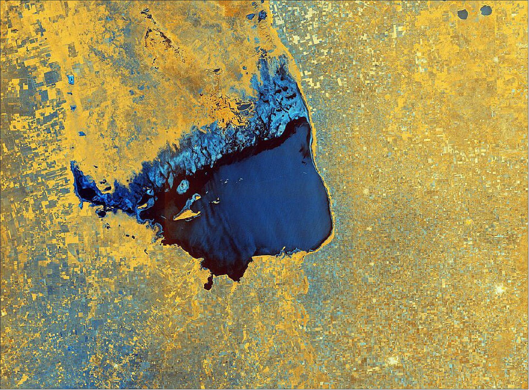
• June 25, 2021: The Copernicus Sentinel-1 mission takes us over Lake Mar Chiquita – an endorheic salt lake in the northeast province of Córdoba, Argentina. 74) The colours of that week’s image come from the combination of two polarisations from the Sentinel-1 radar mission, which have been converted into a single image. As radar images provide data differently than a normal optical camera, the images are usually black and white when they are received. By using a technology that aligns the radar beams sent and received by the instrument in one orientation – either vertically or horizontally – the resulting data can be processed in a way that produces colored images such as the one featured here. Shades of blue in the image show where the differences between the two polarisations are higher, for example the saline marshes in the lake’s north, whereas the crops and agricultural fields in the surrounding area appear yellow, indicating fewer differences between polarisations. Fields, such as those visible in the bottom-left corner of the image, appear blue most likely because they are wetter. Several villages, including San Francisco and Rafaela, are identifiable in white in the bottom-right of the image.
• December 25, 2021: Copernicus Sentinel-1B had been unavailable since 23 December 2021 at 06:53 UTC, no data was being generated.
• December 23, 2021: Copernicus Sentinel-1B is unavailable since 23 December 2021 at 06:53 UTC, no data are being generated. An anomaly occurred onboard. The satellite was in a nominal mode, the SAR had been temporarily switched off.
• October 4, 2021: This week marks seven years since the very first satellite that ESA built for the European Union’s Copernicus program started delivering data to monitor the environment. The Sentinel-1A satellite has shed new light on our changing world and has been key to supplying a wealth of radar imagery to aid disaster response. While this remarkable satellite may have been designed for an operational life of seven years, it is still going strong and fully expected to be in service for several years to come. 70) Launched on 3 April 2014 and delivering a stream of operational data by the beginning October 2014. Copernicus has been the largest provider of Earth observation data in the world for some years now. Copernicus Sentinel-1A exceeded its designed lifetime.
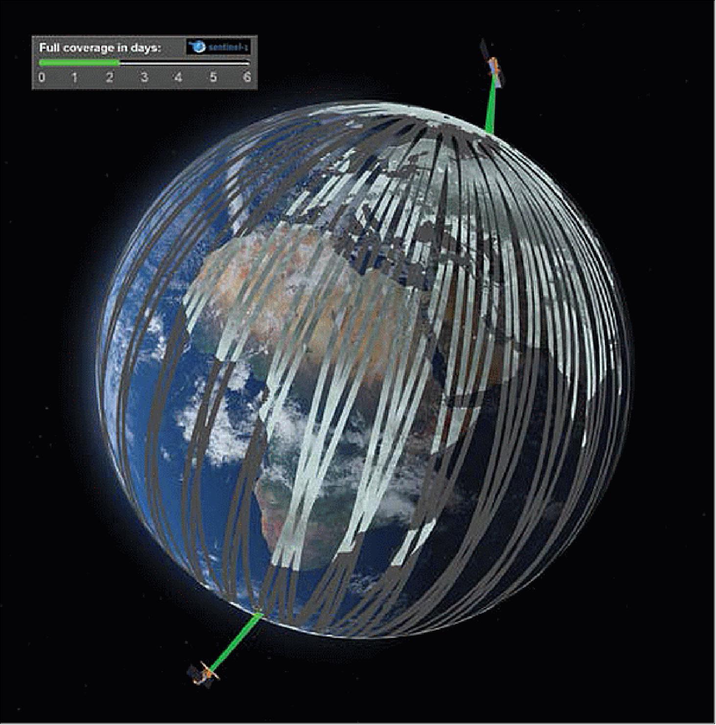
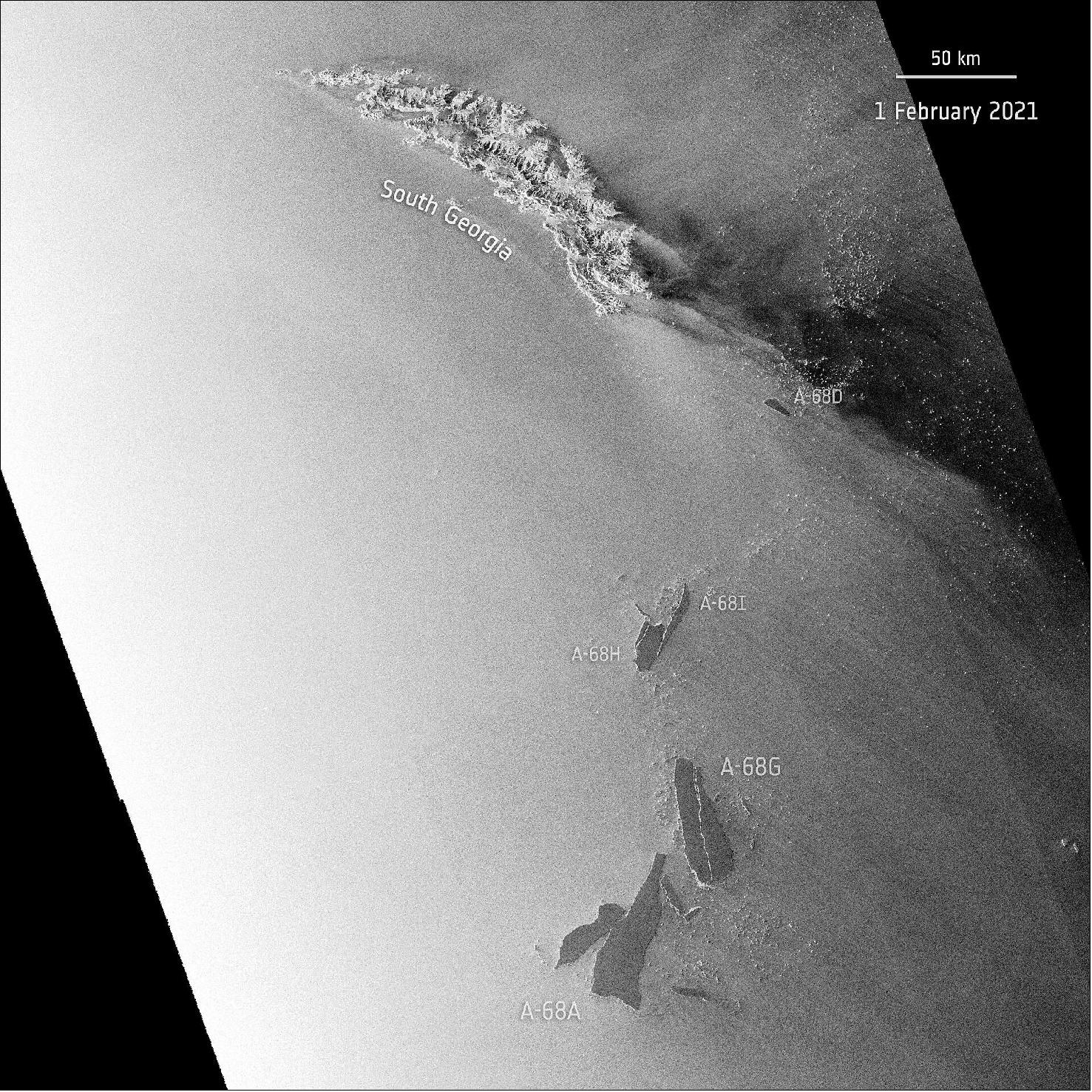
- The Copernicus Sentinel-1 mission comprises two identical satellites orbiting 180° apart to image the planet with a repeat frequency of six days, down to a daily coverage at high latitudes to support operational sea-ice monitoring. Sentinel-1B was launched in April 2016. It is also used for monitoring ground deformation resulting from subsidence, earthquakes and volcanoes, mapping for forest, water and soil management, and mapping to support humanitarian aid and crisis situations. Over the last seven years, the mission has, for example, tracked the huge A-68 iceberg that calved from Antarctica and had a near-collision with South Georgia, has been used in synergy with the Copernicus Sentinel-2 optical mission to map crop types and with ESA’s CryoSat to map ice loss from ice sheets and diminishing sea ice as well as ice lost from the world’s glaciers.
- With the mission designed to work as a pair of satellites, when the time does come for Sentinel-1A to retire, Sentinel-1C will take its place in orbit. The same goes for Sentinel-1B, which will eventually be replaced by Sentinel-1D. The latter two Sentinel-1 satellites will further improve performance and services with new instruments dedicated to marine applications. To ensure the provision of data over next decades, the same approach is taken for the other Sentinel missions.
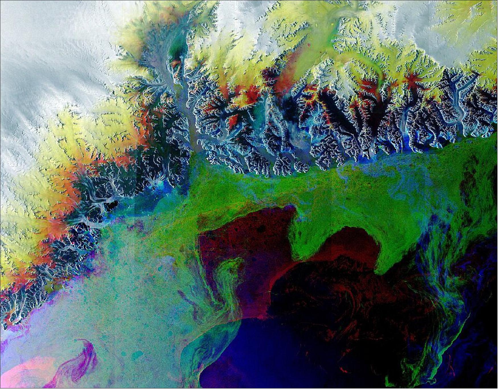
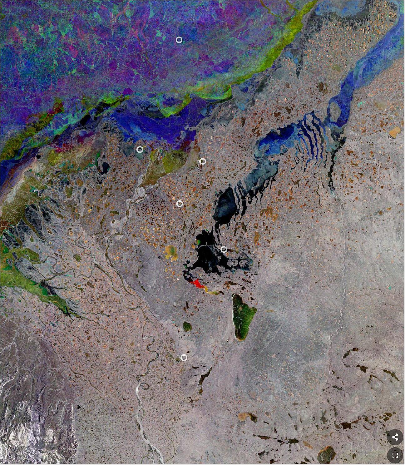
• October 1, 2021: The Copernicus Sentinel-1 mission takes us over the Mackenzie River, a major river system in the Canadian boreal forest. Its basin is the largest in Canada and is the second largest drainage basin of any North American river, after the Mississippi. 71) The landscape pictured here is very typical for these latitudes, with the whole region subject to a harsh winter climate. Satellite data can be used to map permafrost, even in remote and inaccessible areas such as the Mackenzie River delta. The maps, using data from ESA’s Climate Change Initiative, are the longest, satellite-derived permafrost record currently available.
• August 20, 2021: Iceberg A-74, approximately 1.5 times the size of Greater Paris, calved from Antarctica’s Brunt Ice Shelf earlier this year. Over the last six months, it has remained close to the shelf it broke away from owing largely to ocean currents. In early August, strong easterly winds have spun the iceberg around the western tip of Brunt, brushing slightly against the ice shelf before continuing southwards. 72) During the dark winter months in Antarctica, radar images are indispensable because, apart from the region being in a remote region, radar continues to deliver images regardless of the weather or seasonal darkness. The Copernicus Sentinel-1 mission returns images regardless of whether it is day or night, also allowing for continuous imaging during what is now Antarctic mid-winter.
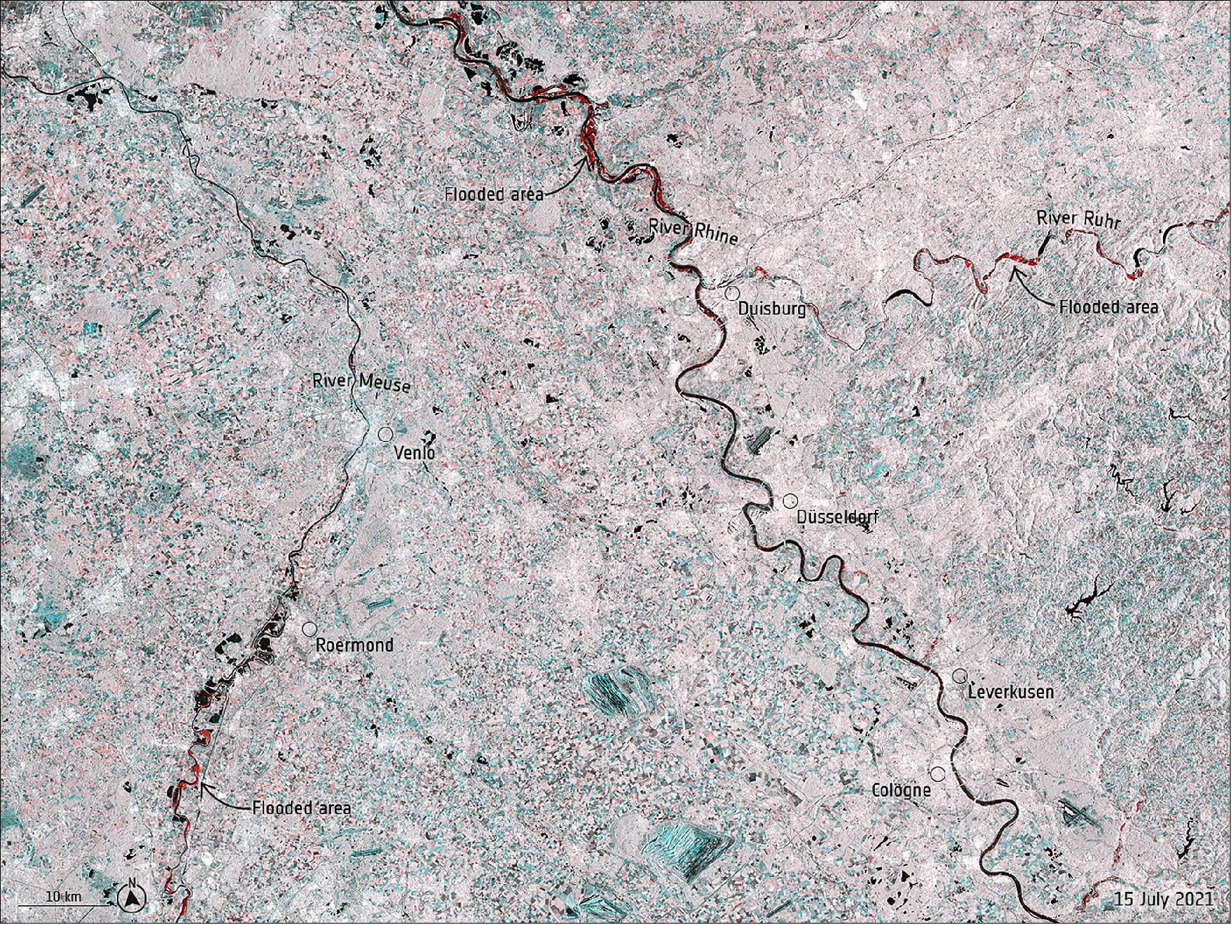
• July 16, 2021: Record rainfall has caused swollen rivers to burst their banks and wash away homes and other buildings in western Europe – leading to more than 90 casualties and over 1000 people missing. Data from the Copernicus Sentinel-1 mission were used to map flooded areas to help relief efforts. 73)The service uses observations from multiple satellites to provide on-demand mapping to help civil protection authorities and the international humanitarian community in the face of major emergencies.
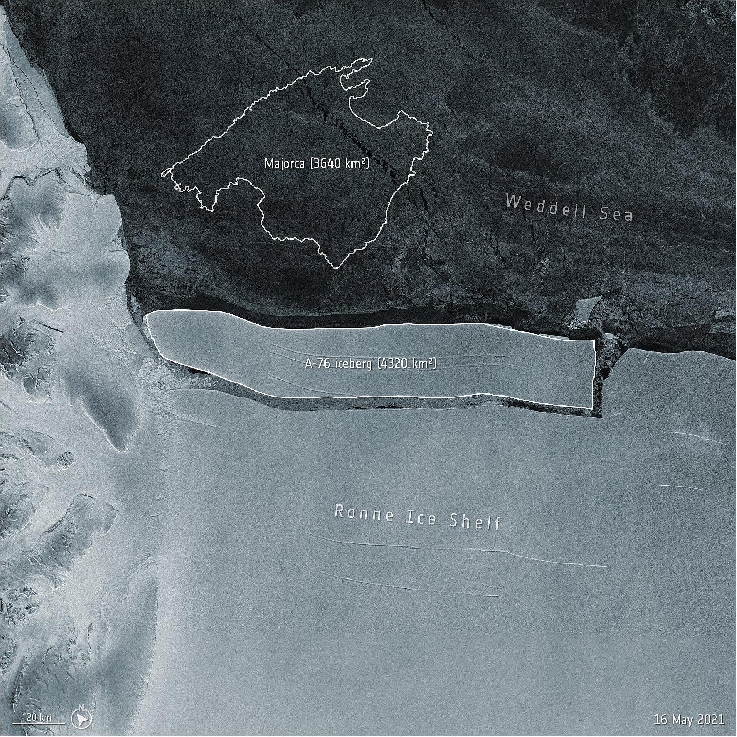
• May 19, 2021: An enormous iceberg has calved from the western side of the Ronne Ice Shelf, lying in the Weddell Sea, in Antarctica. The iceberg, dubbed A-76, measures around 4320 km2 in size – currently making it the largest berg in the world. 75) The iceberg was spotted by the British Antarctic Survey and confirmed from the US National Ice Center using Copernicus Sentinel-1 imagery. The Sentinel-1 mission consists of two polar-orbiting satellites that rely on C-band synthetic aperture radar imaging, returning data regardless of whether it is day or night, allowing us year-round viewing of remote regions like Antarctica.
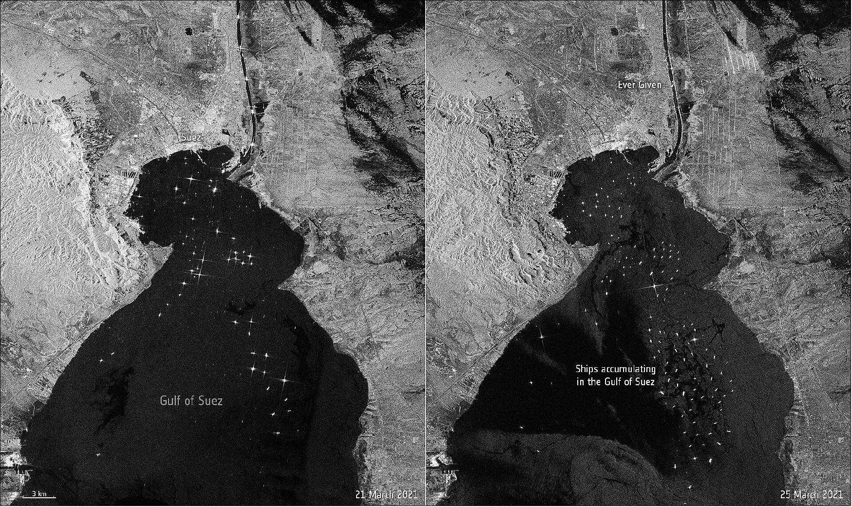
• March 26, 2021: The giant container ship 'Ever Given' ran aground in the Suez canal on 23 March on its journey from China to the Netherlands. The image on the left, captured on 21 March, shows routine maritime traffic in the canal with vessels visible every 2 to 3 km. The image on the right, captured on 25 March, shows the 400 m-ship blocking the canal. 76) The two identical Copernicus Sentinel-1 satellites carry radar instruments to provide an all-weather, day-and-night supply of imagery of Earth’s surface, making it ideal to monitor ship traffic. The sea surface reflects the radar signal away from the satellite, and makes water appear dark in the image. This contrasts with metal objects, in this case the ships in the bay, which appear as bright dots in the dark waters.
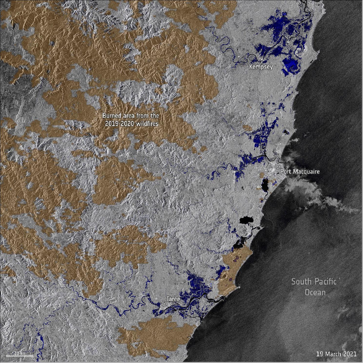
• March 24, 2021: Stretches of land across New South Wales, Australia, have been hit with torrential rain leading to record-breaking floods. The heavy rainfall has caused dams to spill over, rives to burst their banks and thousands of people forced to evacuate their homes. Data from the Copernicus Sentinel-1 mission are being used to map flooded areas to help relief efforts. 77) Data from the Copernicus Sentinel-1 mission have been used by the Copernicus Emergency Mapping Service, activated on 20 March, to map the flooded areas. The service provides information for emergency response to different types of disasters, including meteorological hazards, geophysical hazards, deliberate and accidental man-made disasters and other humanitarian disasters, as well as prevention, preparedness, response and recovery activities.
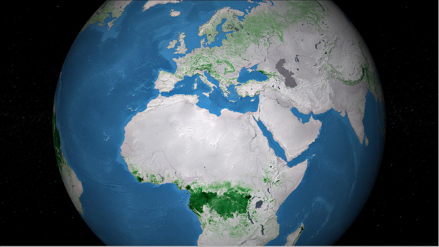
• March 17, 2021: Fluctuations in the carbon-rich biomass held within the world’s forests can contribute to, or slow, climate change. A series of new maps of above ground biomass, generated using space observations, is set to help understanding of global carbon cycling and support forest management, emissions reduction and sustainable development policy goals. 78) Above ground biomass refers to the stem, bark, branches and twigs of woody components of vegetation. New maps, generated by a research team working as part of ESA’s Climate Change Initiative, provide a global view of above ground biomass distribution and spatial density over three separate years – 2010, 2017 and 2018. The maps are derived from a combination of data, depending on the year, from the Copernicus Sentinel-1 mission, Envisat’s ASAR instrument and JAXA’s Advanced Land Observing Satellite (ALOS-1 and ALOS-2), along with additional information from Earth observation sources. Combining new data increases the consistency of high-resolution maps. Earth observation data are routinely used to validate the accuracy, or identify biases, in climate models. The new maps, provided at 100 m resolution, have trimmed uncertainty estimates and will help to further constrain models. The new maps capture the higher biomass levels in high density forest areas, such as in the tropics, due to major improvements to the algorithm.
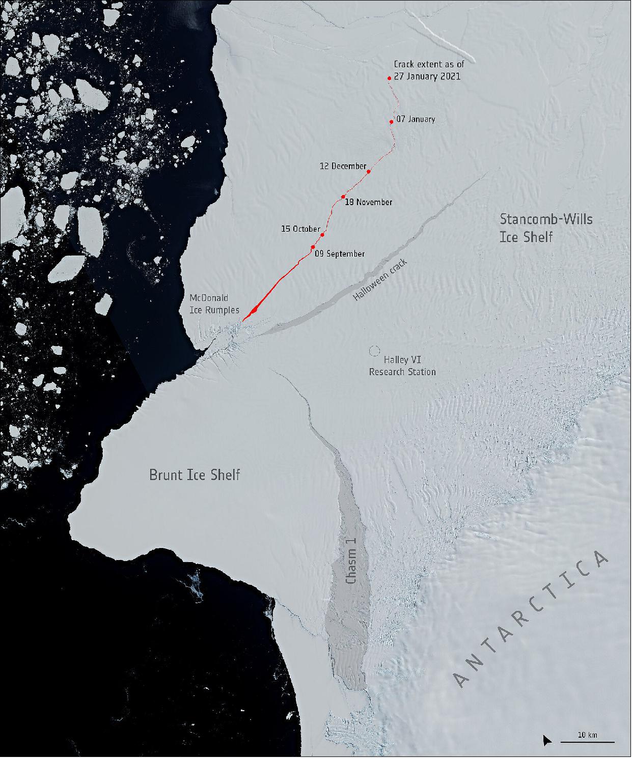
• March 2, 2021: A giant iceberg, approximately 1.5 times the size of Greater Paris, broke off from the northern section of Antarctica’s Brunt Ice Shelf on Friday 26th February. New radar images, captured by the Copernicus Sentinel-1 mission, show the 1270 km2 iceberg breaking free and moving away rapidly from the floating ice shelf. 79)
- Glaciologists have been closely monitoring the many cracks and chasms that have formed in the 150 m thick Brunt Ice Shelf over the past years. In late-2019, a new crack was spotted in the portion of the ice shelf north of the McDonald Ice Rumples. Routine monitoring by satellites offer unprecedented views of events happening in remote regions like Antarctica, and how ice shelves manage to retain their structural integrity in response to changes in ice dynamics, air and ocean temperatures. The Copernicus Sentinel-1 mission carries radar, which can return images regardless of day or night and this allows year-round viewing, which is especially important through the long, dark, austral winter months.
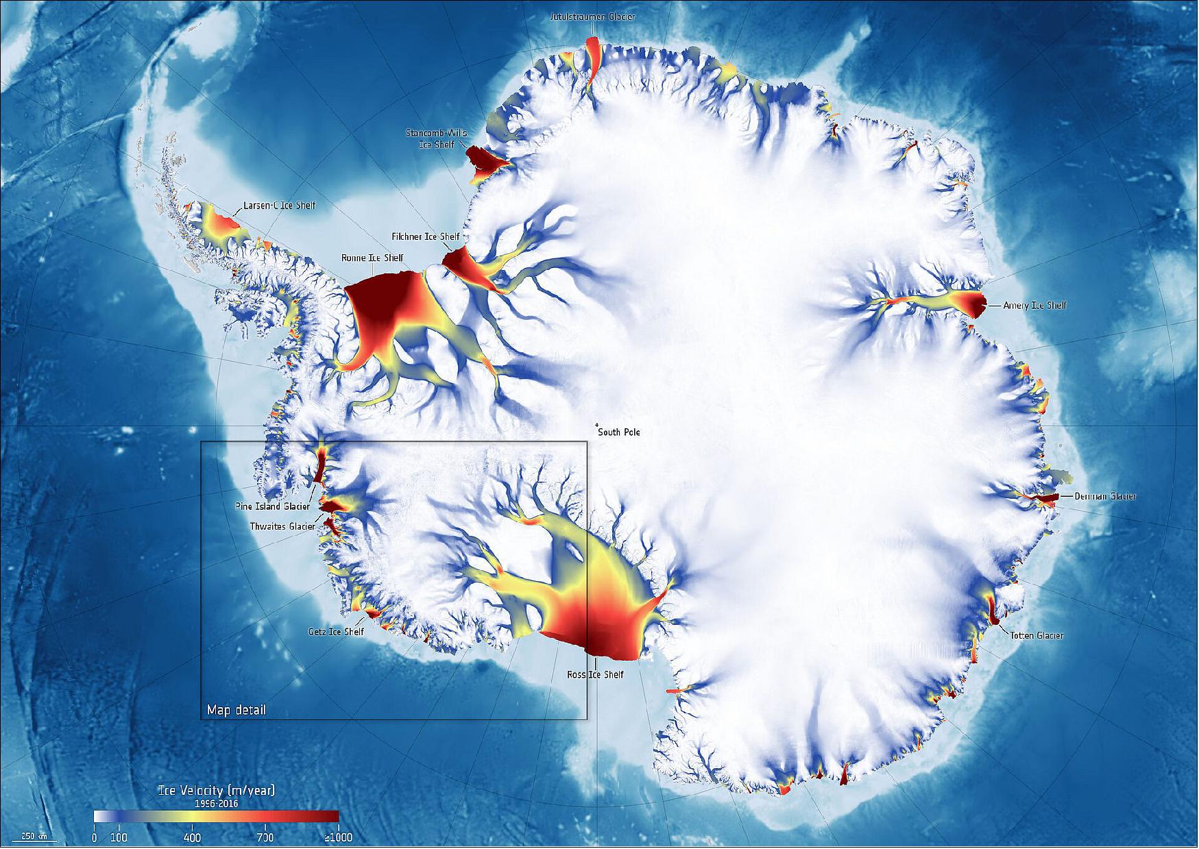
• February 23, 2021: Using a 25-year record of satellite observations over the Getz region in West Antarctica, scientists have discovered that the pace at which glaciers flow towards the ocean is accelerating. This new research, which includes data from the Copernicus Sentinel-1 mission and ESA’s CryoSat mission, will help determine if these glaciers could collapse in the next few decades and how this would affect future global sea-level rise. 80) The scientists used two different types of satellite measurements. Radar data from the Copernicus Sentinel-1 mission, legacy data from the ERS mission through ESA’s Climate Change Initiative and NASA’s MEaSUREs data record allowed them to calculate how fast the glaciers have been moving over the 25-year study period. To measure how much the ice has been thinning, they used altimetry data from ESA’s ERS, Envisat and CryoSat missions through the IMBIE assessment.
• February 19, 2021: Traditionally, optical, or ‘camera-like’, satellite images are used to map different crops from space, but a recent study shows that Copernicus Sentinel-1 radar data along with interferometric processing can improve crop-type mapping 82)The Sentinel-1 mission images are used for numerous applications such as monitoring sea ice and floods, as well as shifts in the land surface or ice surface through the process of interferometry (InSAR) – which is where images of the same place from consecutive satellite passes are compared to reveal differences that occurred between image acquisitions.
- Going further, a paper, published in the IEEE Journal of Selected Topics in Applied Earth Observations and Remote Sensing, describes how Sentinel-1 InSAR can go beyond the measurement of terrain displacement. 83) Part of this research was carried out through ESA’s SInCohMap project, which is dedicated to exploring innovative methodologies for land-cover and vegetation mapping using Sentinel-1 multitemporal InSAR coherence data. The constellation of the two identical Sentinel-1 satellites orbiting Earth 180° apart allows most parts of the world to be imaged every six days. The satellites’ radar instruments can transmit a signal in either horizontal (H) or vertical (V) polarisation, and then receive in both H and V polarisations and then receive in both H and V polarizations.
- The year-long time series of data from 2017 combined pairs of Sentinel-1 images of an agricultural area in Seville, Spain. The images were used to classify 17 different crop types cultivated that year. Coherence was measured by using the pairs of consecutive images, acquired with the separation of six days and at the two polarizations. During the development of the SInCohMap project, all the possible combinations of images acquired in one year were computed and analyzed. In conclusion, the study shows that Sentinel-1 interferometry constitutes a solid source of information for performing crop-type classification, hence going beyond the well-known application of terrain displacement monitoring. Sentinel-1 makes it possible to derive useful information about vegetation and land-cover by using InSAR techniques
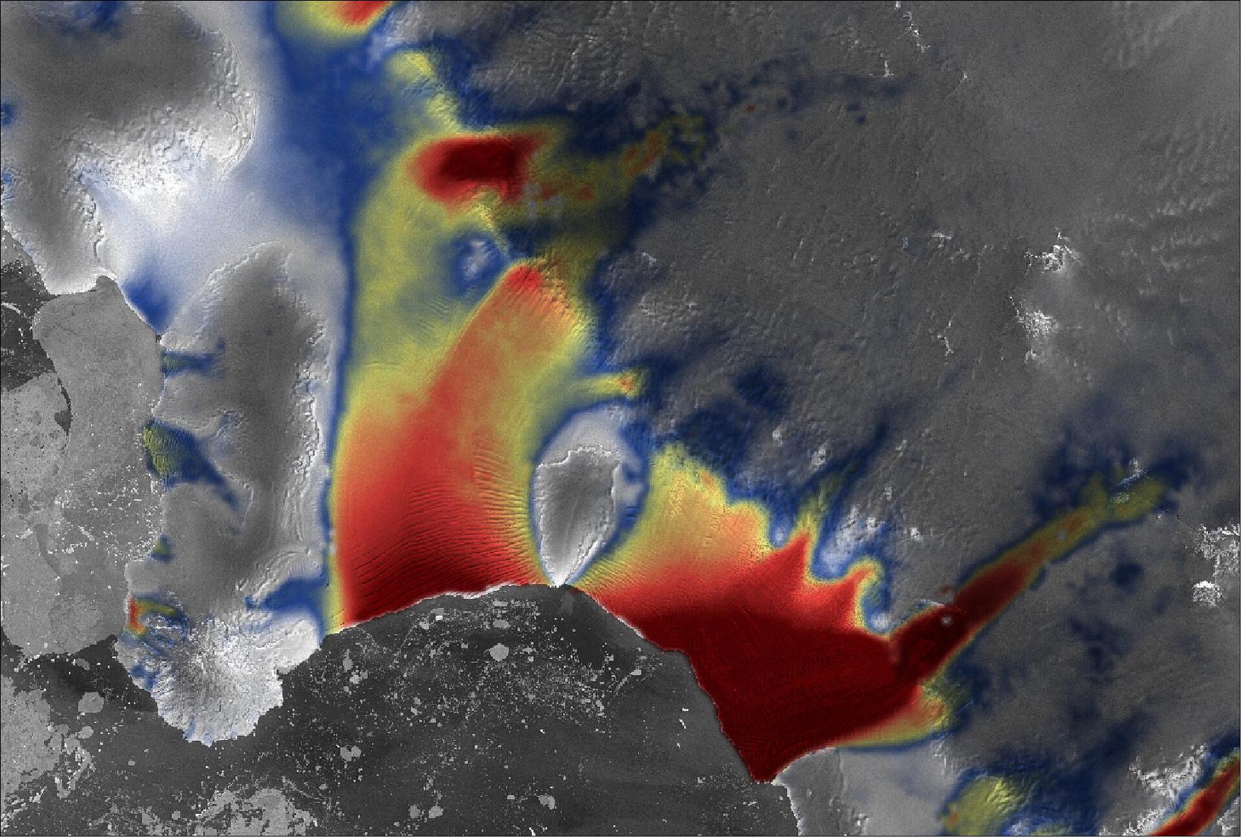
• February 12, 2021: In early 2019, all eyes were fixed on the Brunt Ice Shelf in Antarctica, where a massive iceberg, around the size of Greater London, appeared poised to break off. A more recent, unnamed crack was first noticed in observations from the Copernicus Sentinel-1 mission in late-2019, recently extending by more than 20 km in length. Satellite data has also been used to track the movement and measure the resulting strain in the ice shelf. The map below shows the ice surface velocity on the Brunt and Stancomb-Wills Ice Shelf complex, derived by comparing two Sentinel-1 acquisitions captured on 5 January and 17 January 2021.
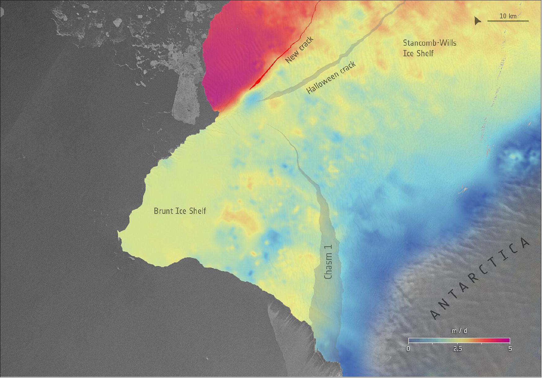
- Satellite data has been used to measure the surface movement of the ice shelf. The map shows the ice surface velocity on the Brunt Ice Shelf, derived by comparing two Copernicus Sentinel-1 acquisitions captured on 5 January and 17 January 2021. (image credit: ESA, the image contains modified Copernicus Sentinel data (2021), CC BY-SA 3.0 IGO)
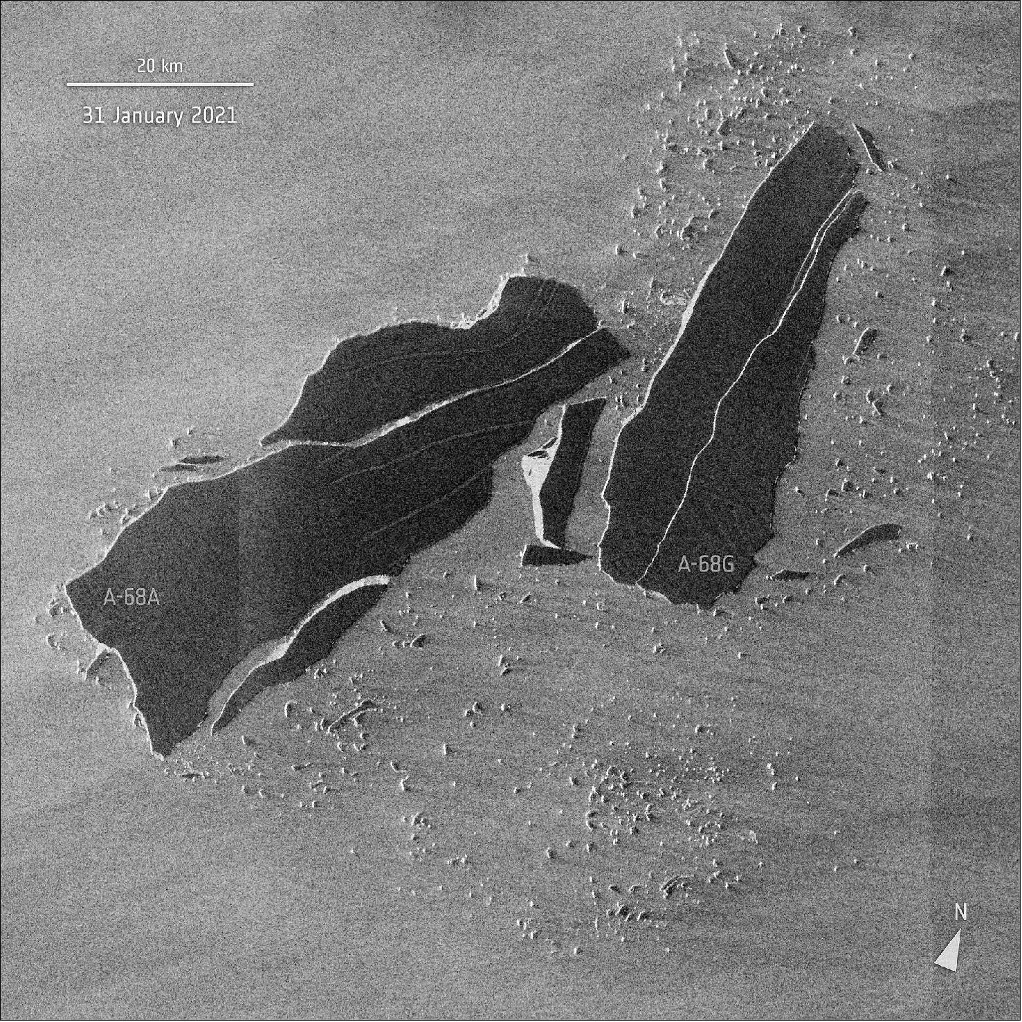
• February 3, 2021: Satellite images have revealed that the once colossal A-68A iceberg has had yet another shattering experience. One of the largest icebergs of all time, A-68A broke off from the Larsen-C ice shelf in 2017 and has been closely monitored over recent months as it veered dangerously close to South Georgia in the South Atlantic 85). Images, captured by the Copernicus fleet of satellites have charted the process of A-68A on its journey over the past three years. Latest data coming from the Copernicus Sentinel-1 radar mission shows the iceberg suffered further damage in 2021 as a new iceberg calved from A-68A just last week.
- Optical imagery from the Copernicus Sentinel-3 mission, while revealing great details of A-68A, is only available in cloud-free conditions. Sentinel-3 and soon, Sentinel-6, radar altimeter measurements can monitor the trajectory of icebergs and are also used to calculate estimates of geostrophic ocean currents that carry A-68A and its children on their journey. Sentinel-1 radar imagery is not affected by clouds, and has been vital in tracking the break-up of A-68A.
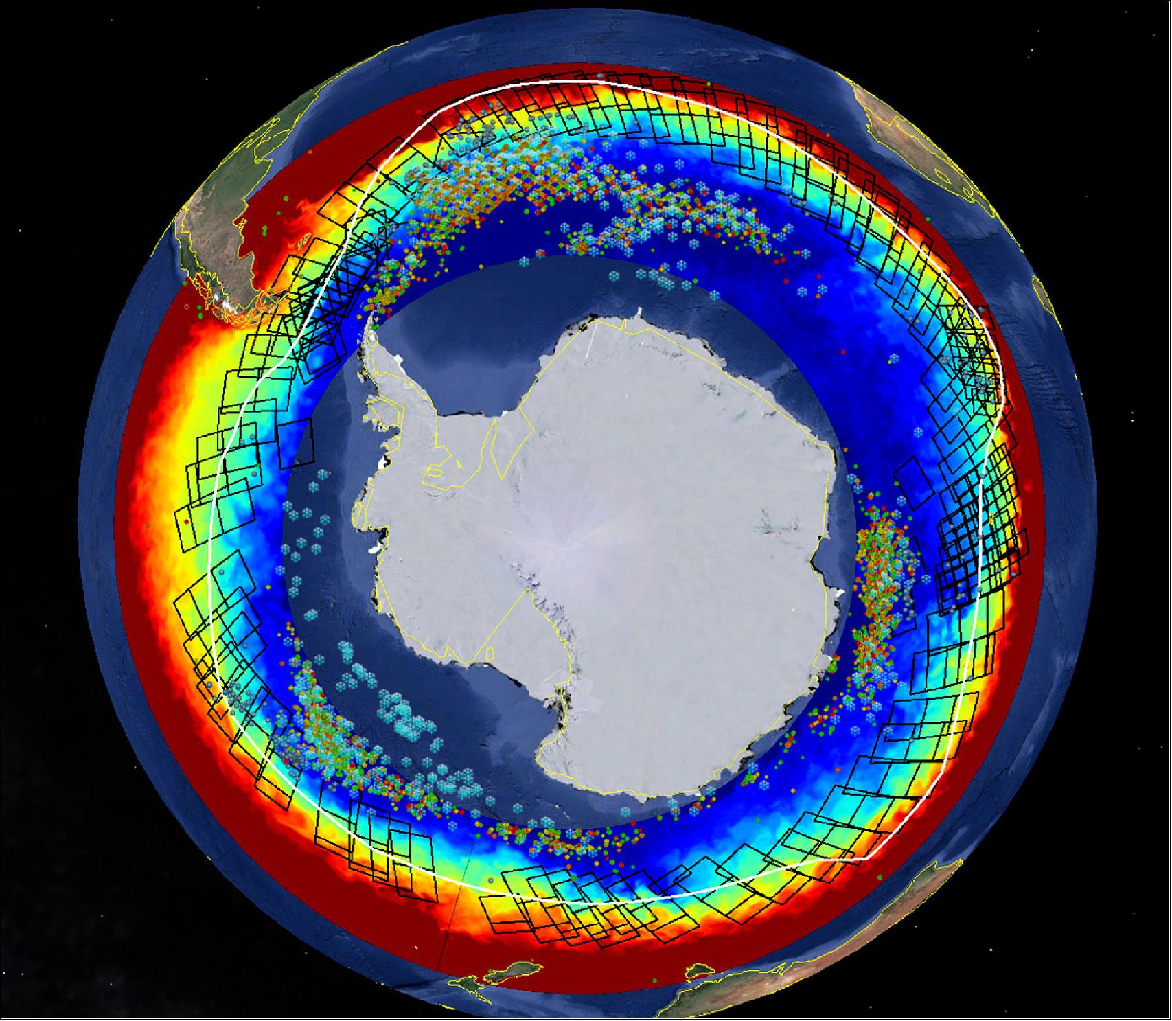
• January 28, 2021: After almost three months at sea, competitors of the Vendée Globe sailing race are now nearing the finishing point back in France, but while they were near the treacherous iceberg-infested waters of the Southern Ocean they remained relatively safe thanks to satellite observations. Read full story: Copernicus satellites keep eyes on icebergs for Vendée Globe. 86) To ensure their safety, CLS, a subsidiary of the French CNES space agency, and CNP used information from satellites to detect and monitor icebergs. This information comes from satellites carrying altimeters, as well as those carrying synthetic aperture radar (SAR) such as Copernicus Sentinel-1. Satellites are the only way of detecting and monitoring icebergs effectively in the remote Southern Oceans.
• January 15, 2021: The Copernicus Sentinel-2 mission takes us over the Tanezrouft Basin – one of the most desolate parts of the Sahara Desert. 87)

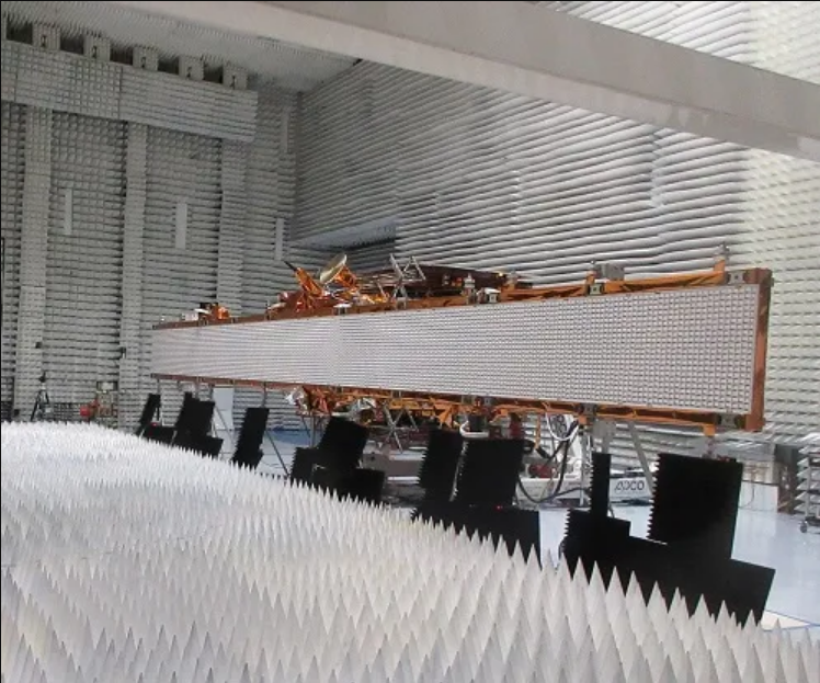
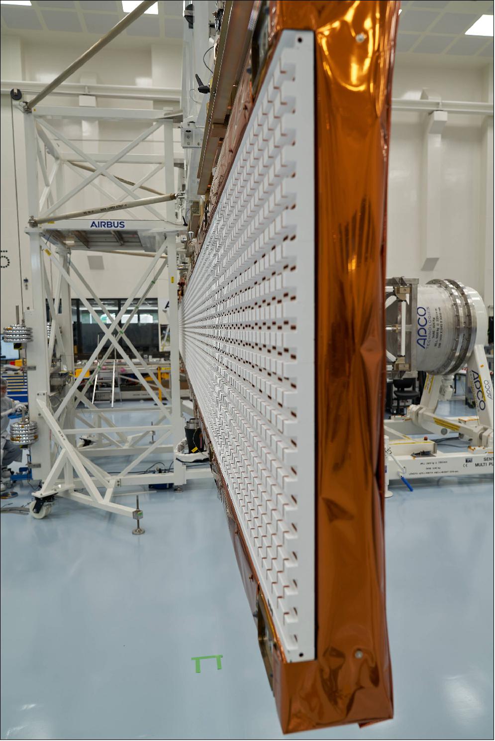
• August 7, 2020: In two years, the next Copernicus Sentinel-1 satellite will be launched to join its two siblings in orbit around Earth. With engineers busy building Sentinel-1C, they have recently tested the mechanism that opens its 12 m-long radar antenna. 57)
- Copernicus Sentinel-1C is the third Sentinel-1 satellite, following Sentinel-1A and Sentinel-1B, which were launched in April 2014 and April 2016, respectively. The three satellites are identical, each carrying an advanced radar instrument to provide an all-weather, day-and-night supply of imagery of Earth’s surface. The mission has been used to monitor the movement of icebergs, ice sheets and glaciers, ground deformation because of subsidence and earthquakes, floods after severe storms, and much more.
- Sentinel-1C is set to ensure the continuity of critical radar images that so many Copernicus environmental services and scientists now rely on.
- The mission’s technical success is thanks to its radar instrument – which when open spans a whopping 12 m. Because the radar is folded to fit into the rocket fairing for liftoff, the deployment mechanism must be thoroughly tested to ensure that all will be well once it is in space.
- This important milestone test has recently been passed at Airbus’ facilities in Germany.
- To simulate this operation in as near realistic environment as is possible on Earth, engineers hang the radar from a structure that helps to mimic weightlessness. The deployment test not only enables the hardware needed for the deployment to be tested, but also allows for the antenna planarity and flatness to be measured when fully deployed.
- Following these deployment test and planarity checks, the instrument will now undergo radio frequency measurements to measure its radiation patterns and radiometric performance.
- A second and last deployment test will be carried out in France, once the radar instrument has been connected to the satellite platform.
- “While, a lot of attention is, quite rightly, devoted to the further expansion of the measurement capabilities of the Copernicus system, we are also focused on ensuring the long-term availability of data produced by the current suite Sentinels to which Europe is fully committed,” says Guido Levrini, ESA’s Copernicus Space Segment Program Manager.
- “This impressive milestone involving the deployment of the huge Sentinel-1C radar antenna - a technological jewel – has, remarkably, been achieved amid the COVID pandemic.”
- Copernicus is the biggest provider of Earth observation data in the world – and while the EU is at the helm of this environmental monitoring program, ESA develops, builds and launches the dedicated satellites. It also operates some of the missions and ensures the availability of data from third party missions.
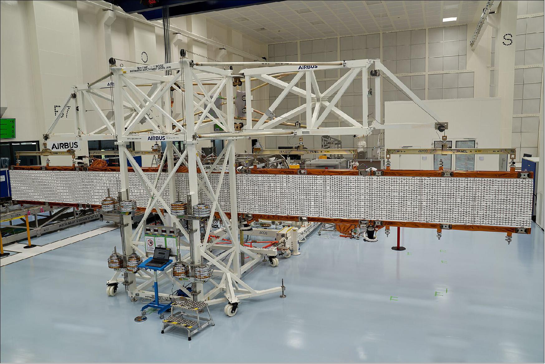
Figure 48: Copernicus Sentinel-1C is the third Sentinel-1 satellite. The three satellites are identical, each carrying an advanced radar instrument to provide an all-weather, day-and-night supply of imagery of Earth’s surface. When deployed in space, the radar measures a whopping 12 meters. Because the radar is folded to fit into the rocket fairing for liftoff, the deployment mechanism must be thoroughly tested to ensure that all will be well once it is in space. To simulate this operation in as near realistic environment as is possible on Earth, the radar is hung from a structure that helps to mimic weightlessness. The deployment test not only enables the hardware needed for the deployment to be tested, but also allows for the antenna planarity and flatness to be measured when fully deployed. The tests were carried out at Airbus in Germany (image credit: Airbus)
Sensor Complement
C-SAR (C-band SAR instrument)
The C-SAR instrument is designed and developed by EADS Astrium GmbH of Germany. The instrument provides an all-weather, day and night imaging capability to capture measurement data at high and medium resolutions for land, coastal zones and ice observations.
The C-SAR instrument is an active phased array antenna providing fast scanning in elevation (to cover the large range of incidence angle and to support ScanSAR operation) and in azimuth (to allow use of TOPS technique to meet the required image performance). To meet the polarization requirements, it has dual channel transmit and receive modules and H/V-polarised pairs of slotted waveguides.
It has an internal calibration scheme, where transmit signals are routed into the receiver to allow monitoring of amplitude/phase to facilitate high radiometric stability.
Sentinel-1's metalized carbon-fiber-reinforced-plastic radiating waveguides ensure good radiometric stability even though these elements are not covered by the internal calibration scheme. The digital chirp generator and selectable receive filter bandwidths allow efficient use of on-board storage considering the ground range resolution dependence on incidence angle.
The goal of the all-weather imaging capability of the C-SAR instrument is to provide measurement data at high and medium resolutions for land, coastal zones and ice observations in cloudy regions and during night, coupled with radar interferometry capability for detection of small (mm or sub-mm level) ground movements, with the appropriate frequencies and operating modes required to support the Copernicus services. 88) 89) 90) 91) 92) 93) 94) 95) 96) 97) 98) 99) 100) 101)
The Sentinel-1 requirements call for the support of four observation/acquisition modes:
• SM (Stripmap mode): 80 km swath with a spatial resolution of 5 m x 5 m
• IW (Interferometric Wide swath) mode: 250 km swath, 5 m x 20 m spatial resolution and burst synchronization for interferometry. IW is considered to be the standard mode over land masses.
- satisfies most currently known service requirements
- avoids conflicts and preserves revisit performance
- provides robustness and reliability of service
- simplifies mission planning & decreases operational costs
- satisfies also tomorrow’s requests by building up a consistent long-term archive.
The IW mode images three subswaths using TOPSAR (Terrain Observation with Progressive Scans SAR). With the TOPSAR technique, in addition to steering the beam in range as in ScanSAR, the beam is also electronically steered from backward to forward in the azimuth direction for each burst, avoiding scalloping and resulting in a higher quality image. Interferometry is ensured by sufficient overlap of the Doppler spectrum (in the azimuth domain) and the wave number spectrum (in the elevation domain). The TOPSAR technique ensures homogeneous image quality throughout the swath.
• EW (Extra Wide Swath) mode: 400 km swath and 25 m x 100 m spatial resolution (3-looks). - Six overlapping swathes have to be foreseen to cover the required access range of 375 km.
• WV (Wave mode): low data rate and 5 m x 20 m spatial resolution. Sampled images of 20 km x 20 km at 100 km intervals along the orbit. The Wave mode at VV polarization is the default mode for acquiring data over open ocean. WV mode is acquired at the same bit rate as SM however, due to the small vignettes, single polarization and sensing at 100 km intervals, the data volume is much lower. The table below shows the main characteristics of the Wave mode.
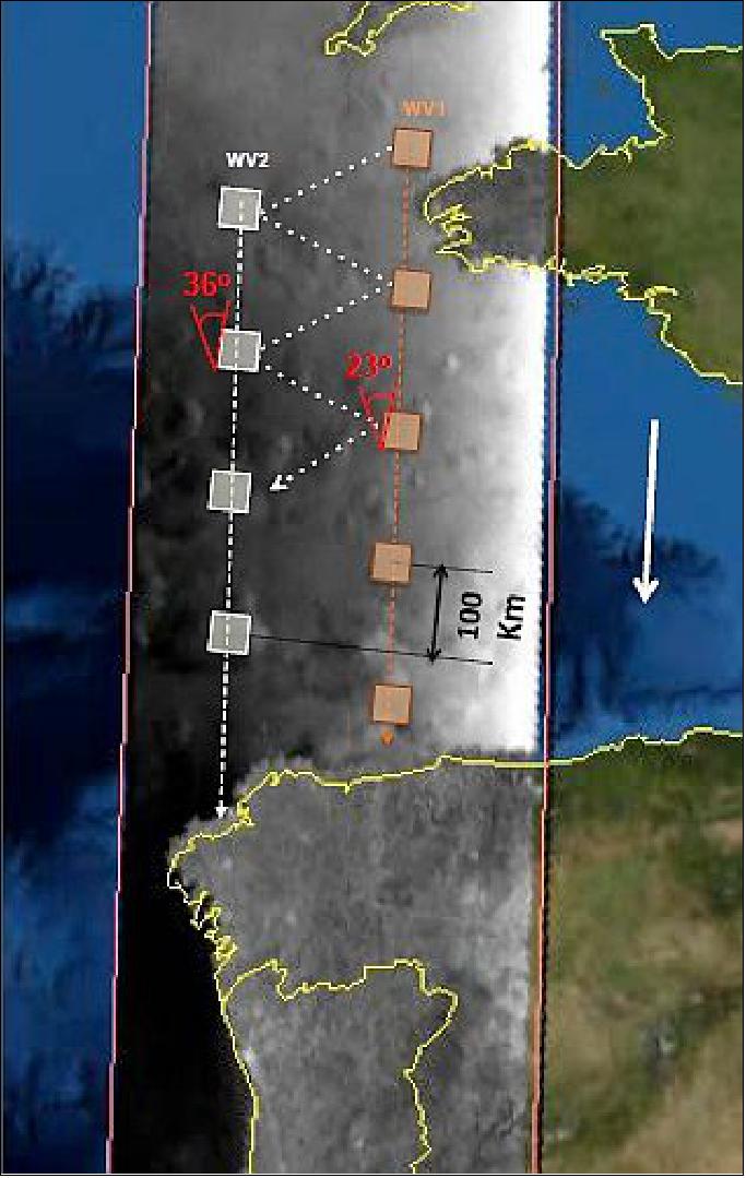
Figure 49: Alternating WV mode acquisitions (image credit: ESA)
Except for the wave mode, which is a single polarization mode (HH or VV), the SAR instrument has to support operations in dual polarization (HH-HV, VV-VH), requiring the implementation of one transmit chain (switchable to H or V) and two parallel receive chains for H and V polarization. The specific needs of the four different measurement modes with respect to antenna agility require the implementation of an active phased array antenna. For each swath the antenna has to be configured to generate a beam with fixed azimuth and elevation pointing. Appropriate elevation beamforming has to be applied for range ambiguity suppression.
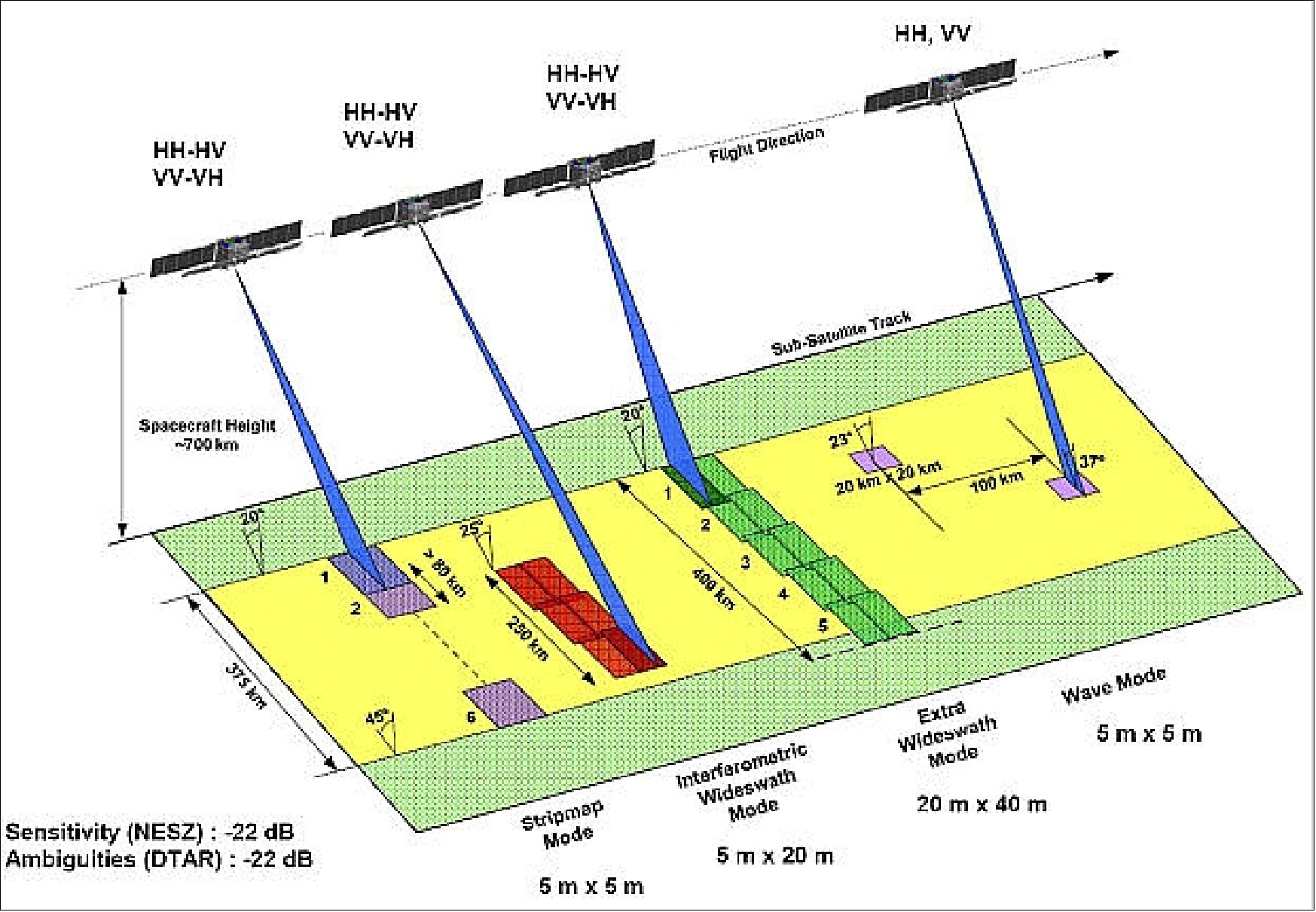
Figure 50: Overview of the Sentinel-1 C-SAR instrument observation scheme and operational support modes (image credit: ESA)
Center frequency of C-band | 5.405 GHz (corresponding to a wavelength of 5.55 cm) |
Bandwidth | 0-100 MHz (programmable) |
Polarization | HH+HV, VV+VH, HH |
Incidence angle range | 20º-46º |
Look direction | right |
Antenna type | Slotted waveguide radiators |
Antenna size | 12.3 m x 0.821 m |
Antenna mass | 880 kg (representing 40% of the total launch mass) |
Azimuth beam width | 0.23º |
Azimuth beam steering width | -0.9º to +0.9º |
Elevation beam width | 3.43º |
Elevation beam steering range | -13.0º to +12.3º |
RF Peak Power (sum of all TRM, at TRM o/p) DC power consumption | - 4.368 kW - 4.075 kW [IW (Interferometric Wide Swath Mode), two polarizations] |
Pulse width | 5-100 µs (programmable) |
Transmit duty cycle | Max 12%, SM 8.5%, IW 9%, EW 5%, WV 0.8% |
Receiver noise figure at module input | 3 dB |
Maximum range bandwidth | 100 MHz |
PRF (Pulse Repetition Frequency) | 1000-3000 Hz (programmable) |
Data compression (selectable) | FDBAQ (Flexible Dynamic Block Adaptive Quantization) |
ADC sampling frequency | 300 MHz (real sampling) |
Data quantization | 10 bit |
Total instrument mass (including antenna) | 945 kg |
Attitude steering | Zero-Doppler steering and roll steering |
The Sentinel 1 mission operational concept foresees the following capabilities and/or services (Ref. 15):
• A continuous and systematic acquisition of data to maximize mission return and system exploitation efficiency.
• A complete Earth coverage after each single orbit repeat cycle (175 orbits in 12 days). This dramatically improves the past and current EO systems’ capabilities; the system supports up to 25 minutes per orbit for STRIPMAP/TOPSAR operations and up to 75 minutes for WAVE operations per orbit
• The minimum revisit time possible on few selected regions, mainly Maritime Transport over European and North Atlantic zones, European coastal zones. A constellation of two satellites, Sentinel-1A and Sentinel-1B, is deployed on the same orbit with a proper phasing.
• The minimum data/product latency after SAR acquisitions: requirements ask for an on-board data latency from a maximum of two orbits (about 3 hours) down to one orbit for the so-called near-real time data down to simultaneous SAR acquisition and data download to ground for real-time data. Basic products will be available, after data downlink, after a maximum of 24 hours for all data, down to 1 hour for near-real time data, down to 10 minutes for L0 products for real time data.
• The capability to include in the pre-defined mission timeline sporadic and asynchronous user orders submitted to the system following emergency occurrences.
• Repeat-pass TOPSAR interferometric capability: accurate burst synchronization and fine orbit control are specific drivers for this system feature.
Introduction of a new SAR imaging mode (new observation technology):
The IW (Interferometric Wide swath) mode is being implemented with a new type of ScanSAR mode called TOPS (Terrain Observation with Progressive Scan) SAR operations support mode (note: the terms TOPS and SAR is simply contracted to TOPSAR). TOPSAR is an ESA-proposed acquisition mode (Francesco De Zan and Andrea Monti Guarnieri) for wide swath imaging which aims at reducing the drawbacks of the ScanSAR mode.
The basic principle of TOPSAR is the shrinking of the azimuth antenna pattern (along-track direction) as seen by a spot target on ground. This is obtained by steering the antenna in the opposite direction as for Spotlight support. The TOPSAR signal includes particularities of both ScanSAR and Spotlights modes, but existing processing algorithms do not provide an efficient processing of TOPSAR data. - The EW (Extra Wide swath) mode is also implemented with the TOPS capability (Table 11).
The TOPSAR mode is intended to replace the conventional ScanSAR mode. The technique aims at achieving the same coverage and resolution as ScanSAR, but with a nearly uniform SNR (Signal-to-Noise Ratio) and DTAR (Distributed Target Ambiguity Ratio). 102) 103) 104)
The TOPSAR mode will be implemented on the Sentinel-1 mission due to the performance advantages compared to ScanSAR. The TOPSAR technique has already been demonstrated on the TerraSAR-X spacecraft during its commissioning phase (fall 2007) and showed very promising results. The measured values of the intensity variation of the analyzed images corresponded very well with the expected theoretical values. Scalloping in the TOPSAR image is 0.3 dB against 1.2 dB in the ScanSAR image. Additionally, fewer bursts are required in TOPSAR, which also positively affects the image quality. 105) 106) 107) 108) 109) 110)
TOPS is employing a rotation of the antenna in the azimuth direction as is shown in Figure 66. Like in ScanSAR, several subswaths are acquired quasi simultaneously by subswath switching from burst to burst. The increased swath coverage is as in ScanSAR achieved by a reduced azimuth resolution. However, in TOPS the resolution reduction is obtained by shrinking virtually the effective antenna footprint to an on-ground target, rather than slicing the antenna pattern, as it happens for ScanSAR. 111)
Concerning the implementation of TOPS InSAR, the Sentinel-1 C-SAR system is designed to enable TOPS burst synchronization of repeat-pass datatakes supporting the generation of TOPS interferograms and coherence maps. Specifically, for the IW and EW modes the TOPS burst duration is 0.82 s and 0.54 s (worst case), respectively, with a requirement for achieving a synchronization of less than 5 ms between corresponding bursts (Ref. 119).
Furthermore, a critical issue for TOPS InSAR performance is the accuracy that is required for TOPS image co-registration. A small co-registration error in azimuth can introduce an azimuth phase ramp due to the SAR antenna azimuth beam sweeping causing Doppler centroid frequency variations of 5.5 kHz.
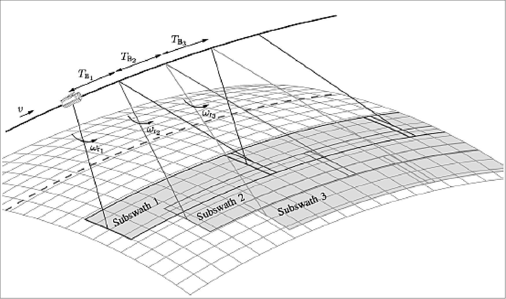
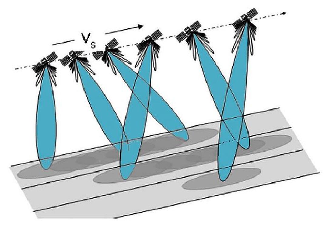
Figure 52: Alternate view of the TOPSAR subswath acquisition (image credit: ESA)
The TOPS demonstration, conducted for ESA in 2007 with TerraSAR-X data, was conducted with the ETT (Experimental TerraSAR-X TOPS) processor; the test was based on sub-aperture processing, the Extended Chirp scaling algorithm and BAS (Baseband Azimuth Scaling). - The SPT (Sentinel-1 Prototype TOPS) processor is based on a pre-processing stage to unfold the azimuth spectrum, a standard ω-k focusing block and an azimuth one-dimensional ‘unfolding’ processing block. It is an extension of the standard ω-k based ScanSAR processor developed for the Envisat ASAR instrument (Ref. 111).
Comparison of both processors: The comparison of the SPT (Sentinel-1 Prototype TOPS) processor with the ETT (Experimental TerraSAR-X TOPS) processor turned out to be a complex task. The results are confirming both processing approaches mutually.
TOPS implementation on RADARSAT-2:
The objective of simulating Sentinel-1 TOPS mode image data products using RADARSAT-2 is to support the implementation of the TOPS mode, specifically the Interferometric Wide swath (IW) mode, on ESA’s Sentinel-1 mission. The use of real C-band RADARSAT-2 TOPS image data enables the preparation for the Sentinel-1 exploitation phase (i.e. GMES Initial Operations (GIO)). In particular, the provision of Sentinel-1 like TOPS image products to operational Copernicus/GMES services and other users will help the user community to prepare and verify their SAR data post-processing chains including ingestion tools etc., before the launch of Sentinel-1A. 112) 113)
The Canadian RADARSAT-2 mission operates at the same C-band frequency (5.405 GHz) as the Sentinel-1 mission. The RADARSAT-2 SAR instrument with its phased array antenna has multiple SAR imaging modes, including ScanSAR modes, as well as it has quad-polarization and repeat-pass SAR Interferometry (InSAR) capabilities. The RADARSAT-2 mission has been implemented as a public-private partnership between the Government of Canada and MDA (MacDonald, Dettwiler and Associates Ltd.), whereby MDA has the commercial data rights.
The design and implementation of the experimental TOPS mode on RADARSAT-2 resembles as closely as possible the performance characteristics of the Sentinel-1 IW mode, within the constraints imposed by the design and implementation of RADARSAT-2. The RADARSAT-2 TOPS image data sets have been processed to Level 1 SLC (Single Look Complex) data with the Sentinel-1 Image Processing Facility (IPF) and are provided in the official Sentinel-1 Level (SLC) product format.
The experimental RADARSAT-2 TOPS mode is referred to as PSNB (Progressive ScanSAR Narrow B). It is based on the existing RADARSAT-2 SCNB (ScanSAR Narrow B) mode. This mode uses 3 sub-swaths, like the Sentinel-1 IW mode, and covers a comparable range of incidence angles.
Instrument Description
The Sentinel-1 satellites carry a single payload consisting of a C-band Synthetic Aperture Radar (SAR) instrument. The instrument is composed of two major subsystems:
• SES (SAR Electronics Subsystem)
• SAS (SAR Antenna Subsystem).
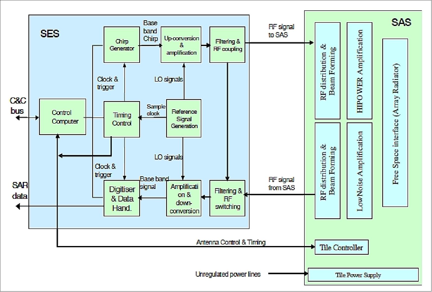
Figure 53: The block diagram of C-SAR (image credit: EADS Astrium, ESA)
The radar signal is generated at baseband by the chirp generator and up-converted to C-band within the SES. This signal is distributed to the HPA (High Power Amplifiers) inside the EFE (Electronic Front End) Transmit/Receive Modules (TRMs) via the beam forming network of the SAS. Signal radiation and echo reception are performed with the same antenna using slotted waveguide radiators. When receiving, the echo signal is amplified by the low noise amplifiers inside the TRM and summed up using the same network as for transmit signal distribution. After filtering and down conversion to baseband inside the SES (SAR Electronics Subsystem), the echo signal is digitized and formatted for recording. 114) 115) 116)
The key design aspects of the C-SAR instrumentation can be summarized as follows:
• Active phased array antenna providing fast scanning in elevation (to cover the large range of incidence angle and to support ScanSAR operation) and in azimuth (to allow use of the TOPS technique to meet the required image performance)
• Dual channel TRM (Transmit & Receive Modules) and H/V-polarized pairs of slotted waveguides (to meet the polarization requirements)
• Internal Calibration scheme, where transmit signals are routed into the receiver to allow monitoring of amplitude/phase to facilitate high radiometric stability
• Metalized CFRP (Carbon Fiber Reinforced Plastic) radiating waveguides to ensure good radiometric stability even though these elements are not covered by the internal calibration scheme
• Digital chirp generator and selectable receive filter bandwidths to allow efficient use of on board storage considering the ground range resolution dependence on incidence angle
• FDBAQ (Flexible Dynamic Block Adaptive Quantization) to allow efficient use of on-board storage and minimize downlink times with negligible impact on image noise.
SES (SAR Electronics Subsystem)
The SES forms the core of the radar instrument connecting the SAS for transmission of Tx pulses and receiving of backscattered pulses from ground targets. The SES provides all radar control, IF/RF signal generation and receive data handling functions comprising: 117)
- radar command and control, timing control, and redundancy control
- transmit chirp generation, frequency generation, up-conversion/down-conversion, modulation/demodulation and filtering
- digitization, data compression and formatting.
A digital chirp generator and selectable receive filter bandwidths allow an efficient use of on board storage capacity considering the ground range resolution dependence on the incidence angle. The radar signal is generated at base band by the chirp generator and up-converted to C-band within the SES. This signal is distributed to the high-power amplifiers inside the EFE TRMs via the beam-forming network of the SAS. Signal radiation and echo reception are performed with the same antenna using slotted waveguide radiators. When receiving, the echo signal is amplified by the low noise amplifiers inside the EFE TRMs and summed up using the same network as for transmit signal distribution.
After filtering and down-conversion to base band inside the SES, the echo signal is digitized and formatted for recording. Flexible dynamic block adaptive quantization allows the efficient use of on-board storage and to minimize downlink times with negligible impacts on image noise.
The SES hardware comprises the following units:
• ICE (Integrated Central Electronics) unit
• MDFE (Mission Dependent Filter Equipment)
• TGU (Transmit Gain Unit)
The ICE unit is the principal module of the SES providing the radar with its core functionality, control and monitoring. The subsystem uses a fully digital design approach for both the derivation of the C-band chirped radar signal and the digital receiver which samples the echo signal at an IF close to base band. The ICE maintains and manages a database of operational parameters such as transmit pulse and beam characteristics for each swath of each mode, and timing characteristics like pulse repetition frequencies and window timings. The MDFE is passive, providing a set of RF filters for the Tx path (to control out-of-band transmissions) and for the Rx path (to limit out-of-band interference). The TGU provides the final RF amplification of the Tx pulse signal before sending it to the SAS. The TGU receives its own dedicated primary power supply from the platform. Switching the TGU on and off is performed by the ICE.
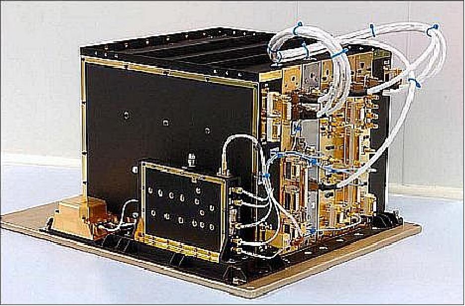
Figure 54: Photo of the SES device (image credit: EADS Astrium Ltd.)
To augment this design and provide mission variable compatibility, the SES also includes mission dependent units that comprise amplification and filtering to provide an ideal signal level and match to the antenna subsystem to be supported.
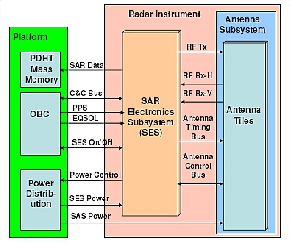
Figure 55: SES context diagram (image credit: EADS Astrium Ltd)
The SES configuration is implemented as a fully cold redundant pair of chains. The TGU being common to both chains only in as much as the two amplifier chains are mounted in a single physical equipment unit before the paths do combine within a passive hybrid device which in turn permits dual outputs to the antenna supplying both fore and aft antenna segments.
The ICE (Integrated Central Electronics) unit is the principal module of SES consisting in turn of highly-integrated modules (Figure 72). ICE is being produced at Astrium UK (Portsmouth). This equipment provides the radar with its core functionality, control and monitoring. The subsystem uses a fully digital design approach for both the derivation of the (up to 100 MHz) C-band chirped radar signal and the digital receiver which samples the echo signal at an IF close to baseband. With single up-conversion and down-conversion stages and data processing using efficient digital filtering and data compression algorithms it is anticipated that this equipment will provide a highly stable core electronics base for this new exciting Copernicus utility. 118)
The Astrium UK ICE design is aimed at providing not only a solution for the Sentinel-1 system but also aims to provide a modern solution for the complex electronics at the heart of radars and particularly that of a SAR. The architecture is designed for adaptability using the inherent flexibility of the digital approach. It is therefore able to adapt easily to the needs of different missions.
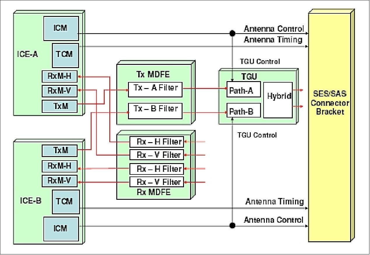
Figure 56: Configuration of SES (image credit: EADS Astrium Ltd.)
The ICE modular design makes use of the integrated RF and digital design technologies now commonly available. High speed ADC (Analog Digital Converter)) and DAC (Digital Analog Converter) components along with flexible design of digital processing through the use of large scale FPGAs and dedicated ASICs, as well as the use of MMIC (Modular Microwave Integrated Circuitry) has allowed the design to respond to the demands of the Sentinel-1 mission.
The design of ICE is comprised of the following elements:
• ICM (Instrument control Module): A Leon ll processor based module, developed by Syderal of Switzerland with:
- PROM for boot software and EEPROM for the application software and the radar characterization database
- Multiple interface formats allowing 1553B communication with the platform, SpaceWire for the internal modules (using the Atmel AT7910/SpW_10X SpaceWire Router ASIC) and CAN for external equipments TGU and SAS.
• Ty module: This RUAG designed and built module uses a direct digital synthesis chirp generation method at an IF of 150 MHz, with up-conversion in a single stage to the nominal 5.405 GHz center frequency to deliver the radars a fully programmable chirp transmission chain. This requires only a further amplification stage provided by the externally provided DAD designed TGU (Transmit Gain Unit) to drive the SAS (SAR Antenna Subsystem).
• Rx modules: The dual polarization approach required by the C-SAR instrument necessitates a pair of matched receive modules to be implemented within the ICE. The receive path is band filtered externally to the ICE by a MDFE (Mission Dependent Filter Equipment) provided by DAD of Finland before its input to the ICE Rx modules Here the signal is down-converted directly to an IF of 75 MHz before being digitized in the ADC which sample's at approx 300 Msamples. This in turn feeds the digital processing chain of a decimation filter followed by, compression and packetization stages before the output is piped to the on board mass memory via a Wizard link interface in a standard CCSDS format at 640 Mbit/s.
• TCM (Timing Control Module): TCM represents the timeline control element for the system. Implementing ECC program driven FPGA logic to provide the necessary timing waveforms required to define and control the within pulse precise timing relationships of all the required timing signals used by the instrument. These timing pulses and the PRI rate communication bus to the antenna are the means whereby the radar establishes the autonomous complex timeline of each mode acquisition with the absolute repeatability required to provide the synthetic aperture quality and the Interferometric property of the system data output.
• PCM (Power Control Modules): These modules are implemented to reduce the individual module voltage conversion effort and to reduce the power losses. These modules use modular common DC/DC converters designed by BLU Electronics to provide 3 voltage rails to all internal ICMs. However, It is to be noted that point of load regulation at module level is still expected for more user specific voltages.
• FDM (Frequency Distribution Module) and USO (Ultra Stable Clock): Using FOAMO (Foam Insulated Master Oscillator) of Astrium as the master clock, the FDM generates the timing reference frequencies used by all other signal modules in ICE. To maintain the highest level of phase stability, this unit also takes in the Tx LO (Local Oscillator) and creates from this the offset Rx down convertor LO for both Rx module channels.
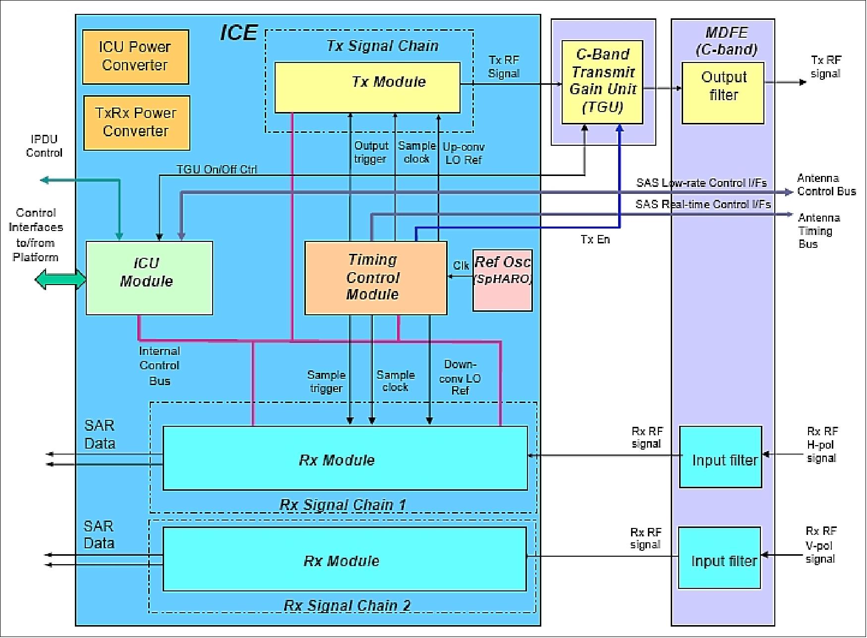
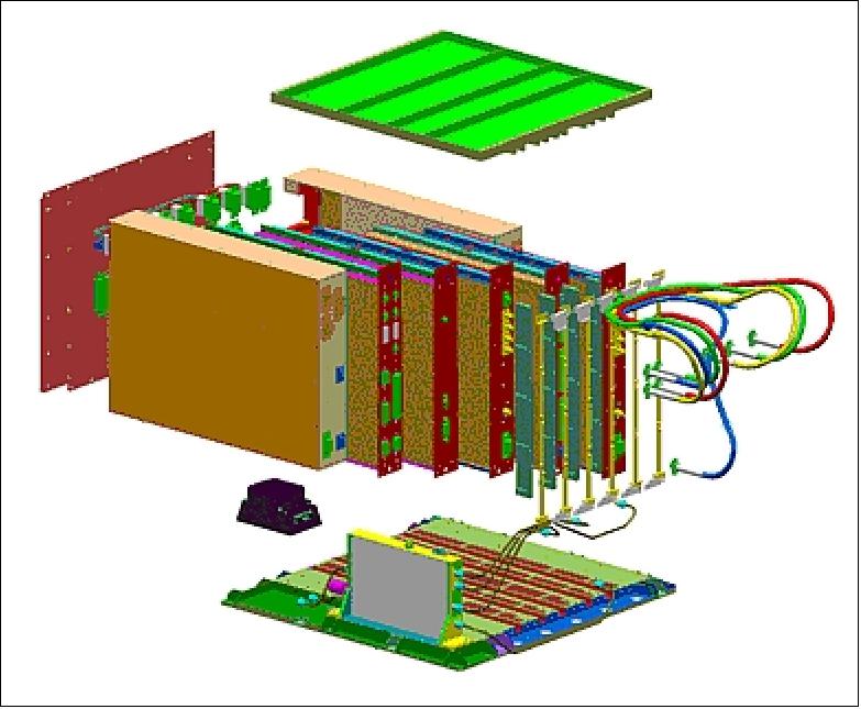
Figure 58: Illustration of the modular configuration of ICE (image credit: EADS Astrium Ltd.)
The ICE equipment has a mass of 20.6 kg. The modules have been selected to be integrated into an equipment enclosure with a backplane wiring loom rather than a fixed motherboard interface plate. This approach allows greater flexibility for test and diagnosis as well as a mechanical flexibility that offers a simpler solution to the thermal challenges of the mission.
The low internal interface count which also allows this open loom approach is in part due to the use of the SpaceWire interconnect for control which has been implemented on the front face of the unit. This being so implemented to facilitate an ESA objective for the ICM module development aimed at further mission systems (Ref. 118).
Roll steering mode (Ref: 93): The roll steering mode of the spacecraft provides a continuous roll maneuver around orbit (similar to yaw steering in azimuth) compensating for the altitude variation such that it allows usage of a continuous PRF (Pulse Repetition Frequency) and a minimal number of different sample window lengths (SWLs) around the orbit. In addition, the update rate of the sampling window position around orbit is minimized (< 1 /2.5 min), which simplifies instrument operations significantly.
Since the instrument can work with a single fixed beam for each swath/sub-swath over the complete orbit, also the number of elevation beams is minimized. The roll steering rate has been fixed to 1.6º/27 km altitude variation. The roll applied to the sensor attitude depends linearly on altitude and varies within the interval -0.8º (minimum sensor altitude) to 0.8º (maximum sensor altitude).
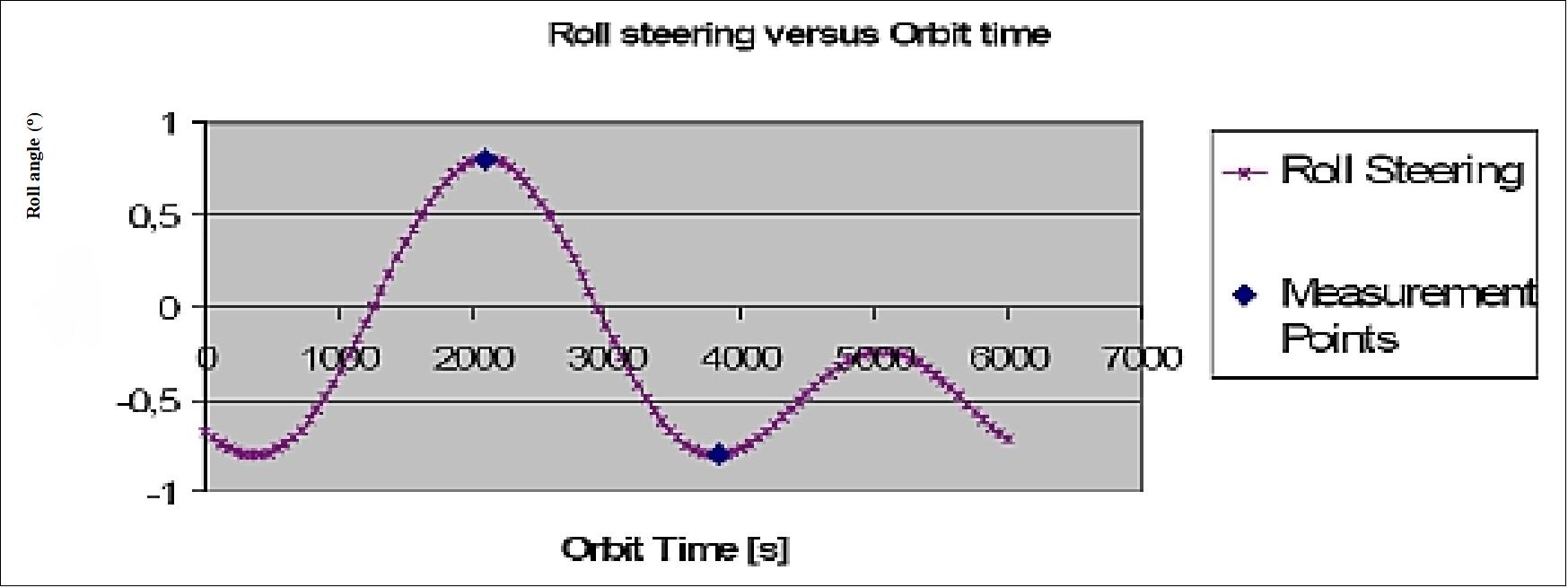
Figure 59: Variation of the roll angle along the orbit (image credit: ESA, TAS)
The attitude steering mode introduces an additional roll angle as a function of latitude to compensate changes in the satellite’s altitude around the orbit, hence maintaining a specific, quasi “constant”, slant range for each SAR imaging mode. This enables the use of a single PRF per swath or subswath around the orbit, except for SM-5 (i.e. different PRF for SM-5N and SM-5S), and a fixed set of constant elevation antenna beam patterns. 119) 120)
Figure 75 illustrates that for the minimum orbital height (693 km) the mechanical SAR antenna off-nadir angle is more shallow (30.25º) than it is for the maximum orbital height (726 km). In the latter case, the mechanical SAR antenna off-nadir angle is 28.65º.
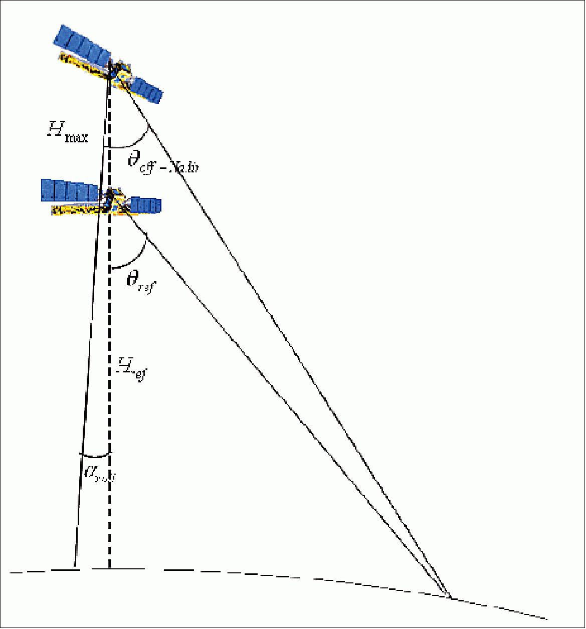
SAS (SAR Antenna Subsystem)
SAS represents the sensor part of the C-SAR instrument and is an active phased array system with Tx and Rx gain and phase control distributed over the antenna area. These functions are provided by so called Transmit Receive Modules (TRMs) as part of the EFE (Electronic Frontend End) assemblies. The SAS is capable of performing rapid electronic beam steering, beam shaping, and also polarization selection. The dual polarized antenna allows at one time either transmission in one single, but selectable polarization (H or V) or simultaneous reception of both H and V polarization. 121) 122)
The SAS consists of 14 identical tiles (12.3 m x 0.84 m) in 5 deployable panels as shown in Figure 76.
The electrical functions of the SAS comprise:
- signal radiation and reception
- distributed transmit signal high power amplification
- distributed receive signal low noise amplification with LNA protection
- signal and power distribution (corporate feed, power converter)
- phase and amplitude control including temperature compensation
- internal calibration loop
- deployment mechanisms, including hold down and release
- antenna mechanical structure.
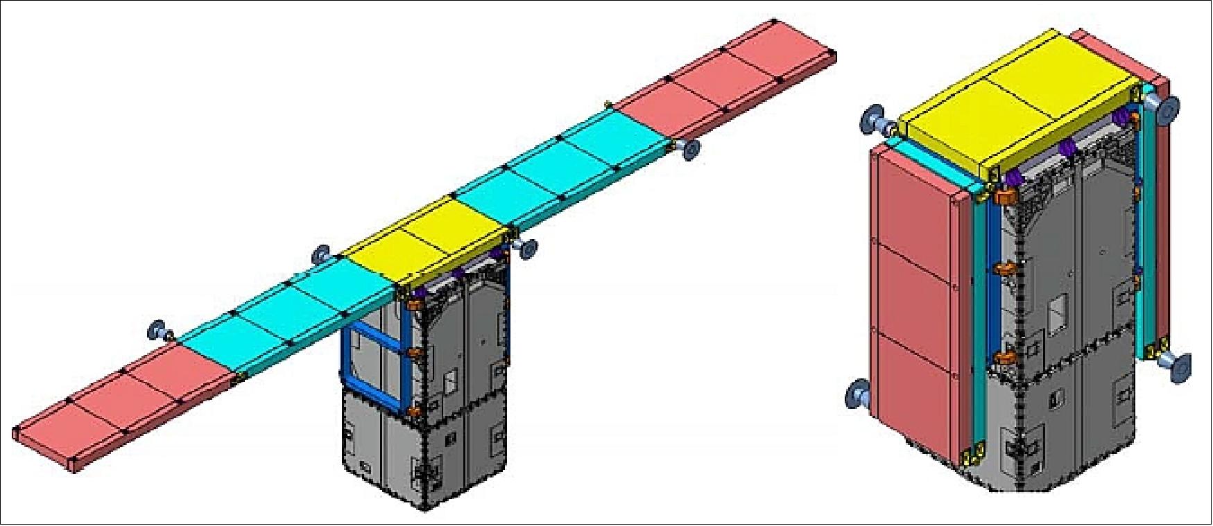
Figure 61: C-SAR antenna in deployed and stowed configuration on the PRIMA bus (image credit: Astrium GmbH)
The instrument is based on a deployable planar phased array antenna carrying TRMs allowing for horizontal and vertical polarizations. The dual polarized antenna allows either transmission in one single but selectable polarization (H or V) or, simultaneous reception of both H and V polarization, at any time. The C-SAR antenna comprises two wings, stowed on the platform's lateral panels during launch, which are deployed once in orbit. Each antenna wing consists of two antenna panels. An antenna panel consists in principle, of a panel frame and several antenna tiles. The SAS central panel comprises two antenna tiles, whereas the wing panels comprise three antenna tiles each. The complete antenna is symmetrical around the middle of the central panel.
The active phased array antenna is capable of performing rapid electronic beam steering, beam shaping and polarization selection, providing fast scanning in elevation and azimuth to cover the large range of incidence angles and to meet the image quality requirements for the TOPSAR mode. TRMs are arranged across the antenna such that, by adjusting the gain and phase of individual modules, the transmit and receive beams may be steered and shaped.
The SAS consists of 14 tiles with 20 dual-polarized sub-arrays on each tile. Each subarray is a dual-polarized unit with two parallel slotted resonant waveguides. The vertical polarization is excited by offset longitudinal slots in a ridge waveguide, while the horizontal polarization is generated by transverse narrow wall slots excited by inserted tilted wires.
A SAS tile is composed of 10 'Waveguide 4' assemblies (two vertically and two horizontally polarized waveguides), which form the smallest building block in the tile manufacturing. Each 'Waveguide 4'-assembly is exposed to a kind of RF-incoming / diagnostic inspection consisting of a passive return loss measurement followed by a measurement of the far-field azimuth pattern in a special anechoic test environment at Astrium GmbH.
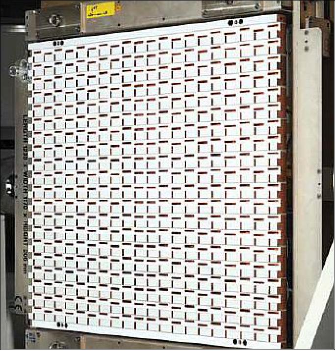
Legend to Figure 77: The instrument comprises three RF networks: Tx network, RxH (H polarization) network and RxV (V polarization) network. During radar operation the Tx network carries the transmit RF signal and the RxH/RxV networks carry the echo signals. The dual polarized antenna allows transmission in one single but selectable polarization (H or V) and simultaneous reception of both H and V polarization.
The tile (size: ~ 0.87 m x 0.84 m) forms the smallest functional entity of the SAS, encompassing all functions necessary to ensure beam shaping / beam steering of the active phased array antenna. The SAS Tile is composed of 10 'Waveguide 4' assemblies and the associated electronics, namely:
- The RF Distribution Network
- 40 Transmit/Receive Modules (20 TRMs for HP & 20 TRMs for VP / supplier: Thales Alenia Space, Italy)
- 2 Tile Controller Units (TCUs)
- 2 Tile Power Supply Units (TPSUs)
allowing signal radiation and reception, distributed transmit signal high power amplification, distributed receive signal low noise amplification with LNA protection, signal and power distribution, phase and amplitude control including temperature compensation and internal calibration.
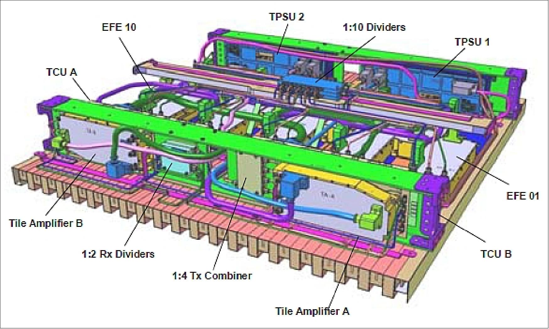
Figure 63: The SAS tile configuration scheme of the SAR antenna (image credit: EADS Astrium)
The CFRP (Carbon Fiber Reinforced Plastic) waveguide radiator is along with the cross stiffeners the major structural element of a tile. All electronic boxes are either placed onto the rear side of the radiators (e.g. the EFEs) or attached to the inner side of the cross stiffeners (e.g. TCU and TPSU). The low loss CFRP slotted waveguides radiators together with the high performance EFE TRMs ensure to meet the stringent sensitivity requirement of -22 dB. The optimized sizing of the overall SAR antenna and its waveguide radiators ensure further that also the ambitious 2D distributed target ambiguity requirement (DTAR) of -22 dB can be met.
EFE is the main transmitting/receiving section of the Sentinel-1 antenna while 195 EFE are necessary to assure the full functionality of the SAR instrument. Each EFE has been optimized for the best trade-off between integration level and RF performances and is composed of four main sections: Power Supply card, Digital card, RF distribution section and the TRM section.
The EFE is composed of four main sections: Digital card, Power Supply card, RF distribution and the TRM (T/R Module) section. A functional scheme of the EFE architecture is shown in Figures 79 and 80.
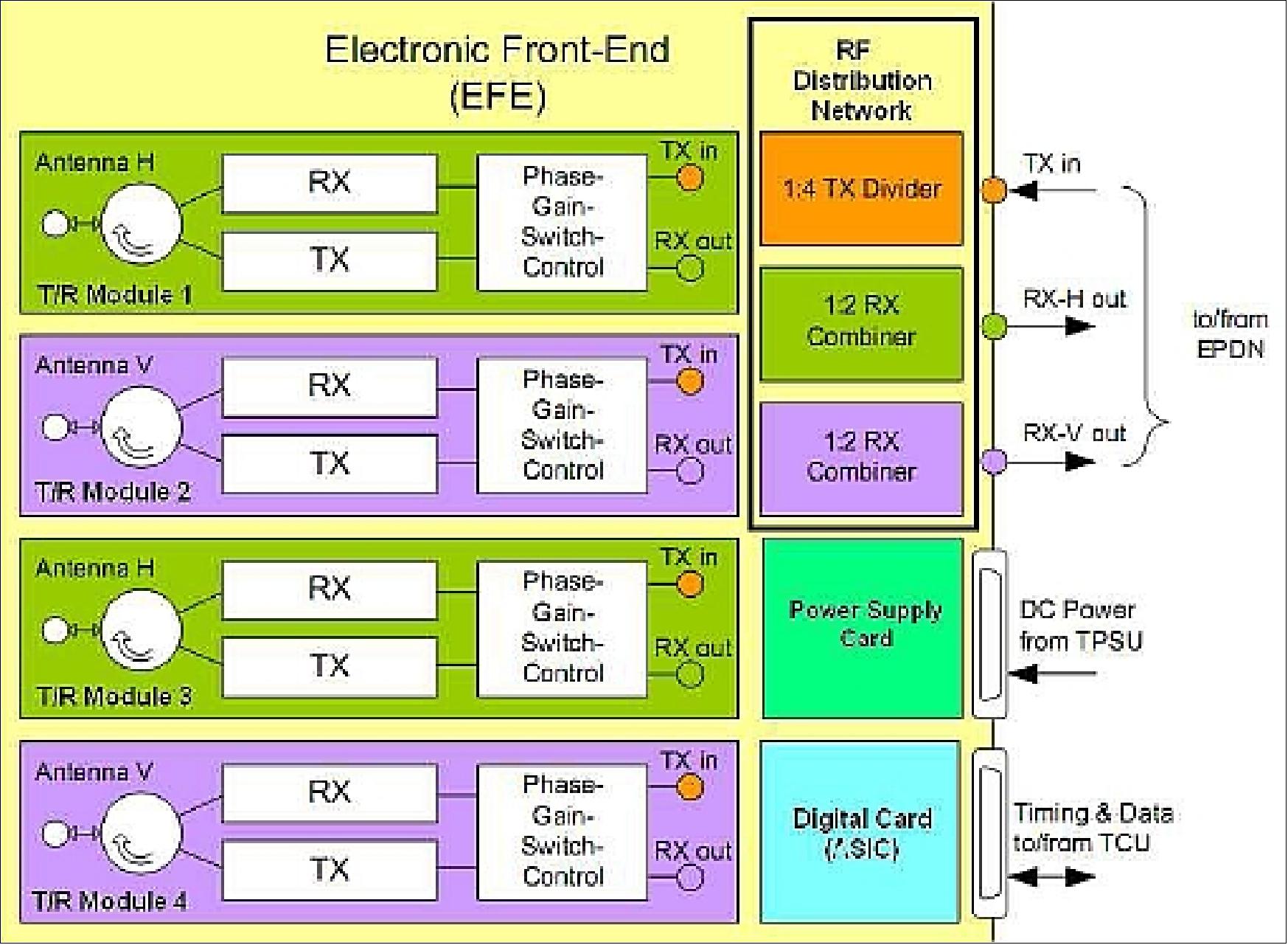
Figure 64: Illustration of the EFE architecture (image credit: TAS-I)
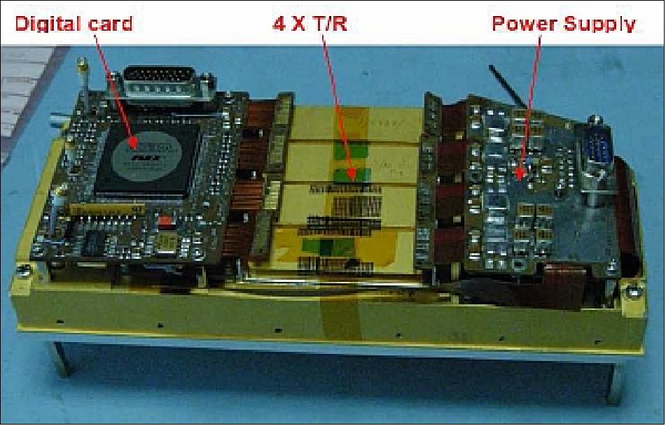
Figure 65: Illustration of the EFE prototype (image credit: TAS-I)
The RF networks provide the EFEs with the Tx pulses, and collect the H and the V polarized echoes. On the tile, these networks form the EPDN (Elevation Plane Distribution Network) which is placed on top of the EFEs (Figure 78). Each network (Tx, RxH, RxV) of the EPDN consists of a 1:10 divider to supply the 10 EFEs. Short cables connect the outputs of the 1:10 dividers to the EFEs.
Operational mode | Polarization | Swath width | Single Look Resolution (range x azimuth) | Access Angles |
Stripmap (SM) | HH-HV or VV-VH | > 80 km | 5 m x 5 m | 20º-45º |
Interferometric Wide Swath (IWS) | HH-HV or VV-VH | > 250 km | 5 m x 20 m | > 25º |
Extra Wide Swath (EWS) | HH-HV or VV-VH | > 400 km | 25 m x 40 m | > 20º |
Wave mode (WM) | HH (23º) or VV (36.5º) | 20 km x 20 km (vignettes at 100 km intervals) | 5 m x 5 m | 23º and 36.5º |
For all modes | ||||
Radiometric accuracy (3σ) | 1 dB | |||
NESZ (Noise Equivalent Sigma Zero) | -22 dB | |||
Point Target Ambiguity Ratio | -25 dB | |||
DTAR (Distributed Target Ambiguity Ratio) | -22 dB | |||
Table 10: Performance parameters of the C-SAR instrument in the various operational modes 123)
The EFE comprises several TRMs (Transmit/Receive Modules) and associated electronics. It represents the active part of the RF equipment of the antenna. The basic function of each EFE is:
• to transmit Tx pulses in one of two polarizations (either H or V) to the corresponding two radiator elements
• to receive the echoes from the two H and the two V radiator elements independently and simultaneously.
The EFE provides the capability to perform antenna beam steering and forming by electronic means:
• control phase setting in transmit
• control phase and gain settings in receive.
C-SAR instrument calibration
In contrast to SAR systems already existing in C-band like ASAR/ENVISAT or RADARSAT-2, high demands on the radiometric accuracy are made for C-SAR on Sentinel-1. Thus, product quality is of paramount importance and the success or failure of the mission depends essentially on the method of calibrating the entire Sentinel-1 system efficiently. 124) 125) 126) 127) 128) 129)
The most important point for the calibration of this flexible SAR system is the tight performance with an absolute radiometric accuracy of only 1 dB (3σ) in all operation modes. Never before has such a strong requirement (a few tenths of dB) been defined for a SAR system.
- Concerning the duration of the Sentinel-1 commissioning phase of three months only, the number of passes and the selection of test sites have to be optimized versus cost and time effort. e.g. calibrating several beams and polarization modes with the same test site. The calibration strategy of Sentinel-1 is based on the experience derived from TerraSAR-X.
Calibration is the process of quantitatively defining the system response to known controlled signal inputs. Calibration tasks are executed throughout the mission to ensure the normalized radar cross-section and the phase of the individual pixels are provided with stability and accuracy. Calibration of the entire SENTINEL-1 system is critical to guaranteeing product quality for operational demands. The SAR system must perform within an absolute radiometric accuracy of only 1 dB in all operation modes. This is a higher radiometric accuracy than any other SAR mission before it.
Calibration can be divided into two forms:
• Internal calibration: Internal calibration provides an assessment of radar performance using internally generated calibrated signal sources, in particular from pre-flight testing.
• External calibration: External calibration makes use of ground targets of known backscatter coefficients to render an end-to-end calibration of the SAR system.
In addition to the commissioning of Sentinel-1B executed by ESA, an independent SAR system calibration will be performed by DLR. For this purpose, the complete calibration chain was developed and established by DLR, starting with an efficient calibration strategy, a detailed in-orbit calibration plan, the SW-tools for analyzing and evaluating all the measurements up to the calibration targets serving as accurate reference. 130)
Internal Calibration
Internal calibration uses calibration signals which are routed as closely as possible along the nominal signal path. The calibration signals experience the same gain and phase variations as the nominal measurement signals. The ground processing then evaluates the calibration signals to identify gain and phase changes and correct the acquired images accordingly.
Transmit power, receiver gain and antenna gain are subject to instrument noise due to temperature changes or other effects over time. Internal calibration provides corrections for changes in the transmit power and the electronics gain as well as validating the antenna model. The resulting calibration data are used in ground processing to correct image data.
Internal calibration also covers the signal phase. The overall phase of the echo signal depends on two major elements: measurement geometry and instrument internal phase stability. As the hardware cannot generally provide the required phase stability, it is a task of the internal calibration scheme to cover the internal phase variations by adequate measurements. All internal calibration measurements, either for gain or for phase, are used in ground processing to correct data products and achieve the required stability.
Internal calibration uses a PCC (Pulse-Coded Calibration) technique to embed a unique pulse code on a signal such that it can be identified and measured when embedded in other signals. This allows the amplitude and phase of individual signal paths to be measured while operating the complete antenna. The PCC technique is implemented by sending a series of coherent calibration pulses in parallel through the desired signal paths. The individual successive signals are multiplied by factors of +1 or -1. Factor -1 is implemented by adding a phase shift of 180°, while factor +1 means no additional phase. Each path is identified by a unique sequence.
The PCC technique can be applied if:
- the receiver detects the signals coherently
- the whole sequence is executed in a sufficiently short time such that the parameters to be measured are stationary
- the system is linear concerning the individual signals.
The PCC technique can measure the signal paths via individual Transmit (TX) /Receive (RX) Modules (TRMs) or via groups of TRMs (either TX or RX paths, either polarization).
The average properties of rows or columns of TRMs can be measured by a short PCC sequence. The length of a PCC sequence is always a power of two. There are 20 rows of waveguides, therefore the PCC sequence has a minimum of 32 pulses. Although the 14 columns (14 tiles) could be measured by a PCC sequence of 16 pulses, it is assumed that a sequence length of 32 pulses is also used. All 20 rows are operated together, meaning the antenna is in a full operational state. The overall signal from all rows is received, digitized and packed into calibration packets. These packets are evaluated (on the ground) to determine the properties of the individual rows. The approach for measuring the average azimuth excitation coefficient is similar to the elevation pattern, using columns of TRMs instead of rows.
The PCC-32 measurements described above need approximately 129 pulses. Additional warm-up pulses may also be needed. Such a large number of calibration pulses represent a significant interruption in image generation when operated within the image acquisition of the stripmap mode. For intermediate calibration pulses in stripmap mode, and also for calibration pulses related to each sub-swath measurement in the ScanSAR modes, a shorter sequence is needed. The shortest possible PCC sequence is based on two measurements, however this procedure introduces PCC-inherent error contributions. These latter errors are to be expected, although they are significantly smaller than those due to leakage signals.
For the antenna model, the reference patterns of all beams are derived for radiometric correction of the SAR data. The active antenna of the SAR instrument allows a multitude of different antenna beams with their associated gain patterns. All these patterns are described by the mathematical antenna model which provides the antenna patterns as functions of the commanded amplitudes and phases within the front end EFEs and within the tile amplifiers. The quality of the patterns is ensured by the on-board temperature compensation controlled by the tile control units. The internal calibration signals measure the actual phases and amplitudes and allow verifying the correct function and performance of all included elements. The antenna model is established on-ground, based on pattern tests at various integration levels up to the complete antenna.
RF Characterization Mode:
The RF characterization mode is a self-standing mode and is not associated with the individual imaging data-takes. It is operated at least once per day during a convenient point within the long duration of wave mode.
The RF characterization mode verifies in-flight the correct function and characteristics of the individual TRMs. Operating it two or more times at different temperatures during the cool-down phases between the high dissipating imaging modes can provide in-orbit characterization versus temperature where necessary. The RF characterization mode performs measurements with internal signals and is designed to achieve several goals. The RF calibration mode will:
- cover all those measurements needed in-orbit but which are not required for each individual data-take
- provide data sets to assess the instrument health and performance as far as possible
- verify the correct function of the individual TRMs, both within the front-end and the tile amplifiers
- verify the excitation coefficients for the TX and RX patterns to ensure the validity of the antenna model.
This mode is based on the same measurement types as the internal calibration. The mode has to address the individual TRMs while operating the full antenna in representative thermal conditions and with nominal power consumption. This can be achieved using the PCC technique. As a standalone mode, it is not forced to use the signal parameters of a dedicated imaging mode, but instead an optimized set of parameters can be used. The calibration mode is to be operated for both TX polarizations. The receiver will measure both polarizations in any case.
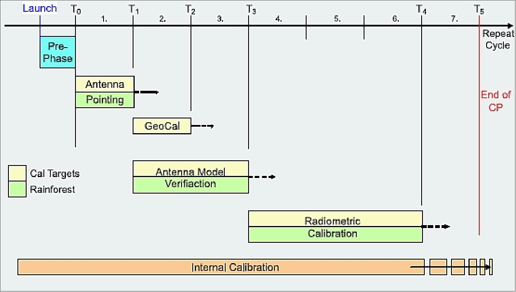
External Calibration
External calibration derives the calibration constant by measurement of corner reflector targets and homogeneous areas such as rainforest with exactly known backscatter coefficients. This is necessary as it will not generally be possible to know all parameters with sufficient accuracy before the in-flight measurements.
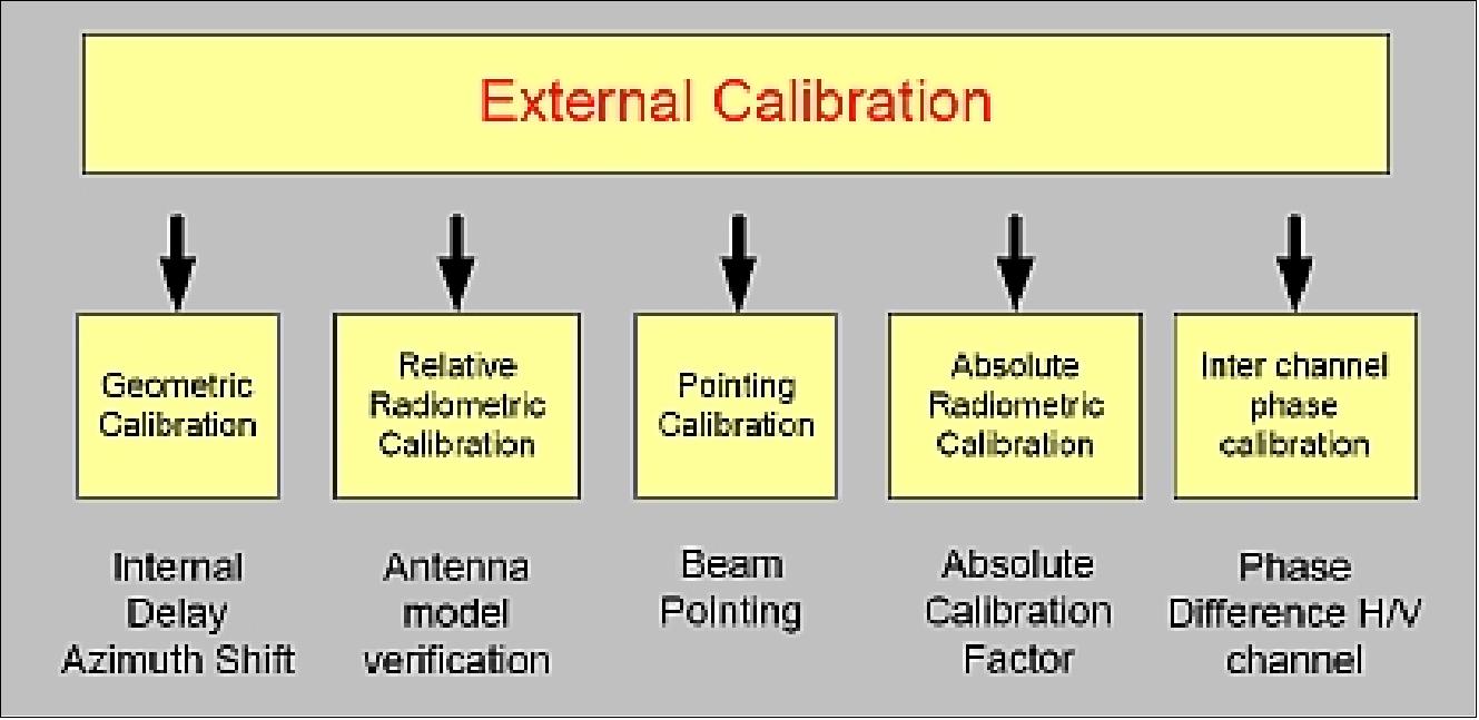
Figure 67: In-orbit external calibration (image credit: ESA)
External calibration comprises five steps as shown below.
1) Radiometric Calibration: Radiometric calibration is applied to correct for the bias of SAR data products. The required absolute calibration factor is derived by measuring the SAR system against reference point targets with well-known radar cross section. Due to the high demand on the radiometric accuracy of 1 dB (3σ) in all four operational modes, it is recommended to measure at least one beam of each mode against the SENTINEL-1 transponders deployed at different locations. Each selected beam will be measured during two passes (ascending and descending). Furthermore, two receive polarization combinations per operation mode are to be measured simultaneously. By measuring SENTINEL-1 against the three transponders for selected beams, the radiometric calibration can be performed within a limited number of repeat cycles. The absolute calibration factor of all other beams is then derived by applying the antenna model.
2) Antenna Model Verification: Antenna model verification ensures the provision of precise reference patterns of all operation modes and the gain offset between different beams. Verification of the antenna model is performed for selected beams, at least one with low, one with mid- and one with high incidence angle, all with the same polarization condition. In addition, some of the beams are selected for measuring the second polarization condition. Assuming acquisitions for each of the selected beams, using the receiver mode of the transponders and by using acquisitions over rainforest, antenna model verification can be performed within a few cycles.
3) Geometric Calibration: Geometric calibration is applied to assign the SAR data to the geographic location on the Earth's surface. Using well surveyed reference targets, the internal delay of the instrument and systematic azimuth shifts can be derived. For this purpose the acquired scenes are measured simultaneously against point targets deployed and precisely surveyed.
4) Antenna Pointing Determination: Antenna pointing determination is performed to achieve correct beam pointing of the antenna. The determination of the antenna pointing by the receiver mode of the transponders is performed using notch patterns in azimuth with different incidence angles (near, mid- and far). Using three transponders with a receiver function within one cycle (two passes) sufficient measurements can be acquired to derive the required accuracy. The appropriate antenna pattern is measured across the rainforest and using ground receivers.
5) Inter-Channel Phase Calibration: As the signal travels through different receive channels for H and V polarization, it may experience different gains, phase offsets and even different time delays. Inter-channel phase accuracy is calibrated using the SENTINEL-1 transponders that return the signal with H and V polarization components, and which therefore allow a direct phase comparison between H and V channels. The antenna model to be derived on the ground describes the antenna patterns with high accuracy. This antenna model is verified for a limited set of elevation beams via measurements over a homogeneous target, i.e. over rainforest. The azimuth beams will be measured using the receiver function of the SENTINEL-1 transponder.
Independent calibration verification
In addition to the commissioning of Sentinel-1A executed by ESA, an independent verification of the system calibration will be executed for the first time by an external institution. For this purpose, the complete calibration chain was developed and established by DLR, starting with an efficient calibration concept, a detailed in-orbit calibration plan, the SW-tools for analyzing and evaluating all the measurements up to the calibration targets serving as accurate reference. 131)
DLR calibration facility: The Sentinel-1 calibration strategy requires a facility that is well-equipped with ground calibration hardware as well as software tools for analyzing and evaluating all the measurements. For this purpose, DLR/MRI (Microwave and Radar Institute) has been developed and established the following reliable and accurate ground equipment:
• Accurate and remote controlled ground targets like the DLR’s novel corner reflectors as depicted in Figure 83 and the novel transponders as depicted in Figure 84, precisely surveyed for geometric and radiometric calibration. Using the receiver unit of the transponder, the pointing and the pattern of the antenna in azimuth direction can be measured during an overflight.
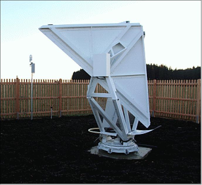
Figure 68: DLR’s novel corner reflector which is remote controlled (image credit: DLR)
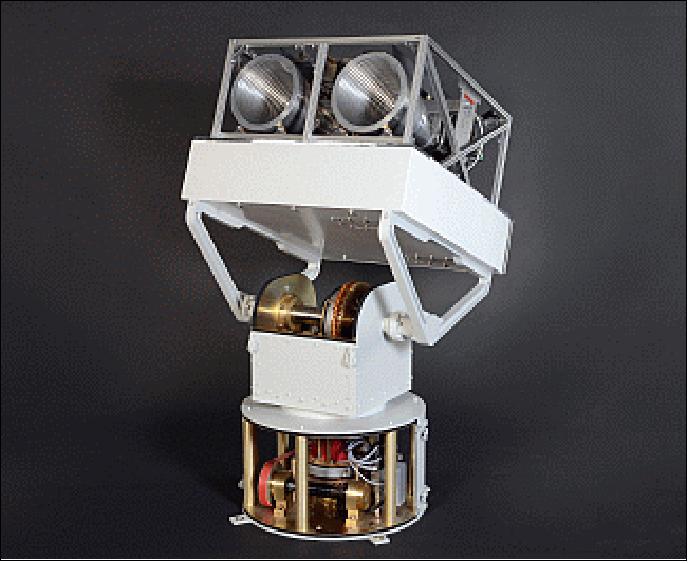
Figure 69: DLR’s novel transponder, designed and developed for Sentinel-1A (image credit: DLR)
• Different analysis and evaluation tools have been modified w.r.t. the Sentinel-1A characteristics, like:
- Internal Calibration Module for analyzing the stability of the instrument and deriving several instrument offsets like the channel imbalance.
- Antenna Characterization Module for deriving the actual pointing of Sentinel-1A and verifying the antenna model in-flight
- CALIX, a software tool for point target analysis and deriving the absolute calibration factor. Furthermore by geometric analysis of accurately surveyed targets the internal delay of the instrument and the dating of the SAR data can be determined.
- TAXI, the Institute’s experimental TanDEM-X interferometric processor, which will be used for interferometric analysis and for phase analysis of the TOPS mode of Sentinel-1A.
Test site selection: The next important point is concerned with the coverage of Sentinel-1A, because the coverage defines the number of visible measurements across a test site and drives consequently the schedule. Considering all aspects described before, the coverage of Sentinel-1A across the DLR calibration field in South Germany has been investigated for all beams being selected for in-flight measurements, as depicted in Figure 85 by the blue hatched swathes. The red framed area indicates a region covering all beams. Hence, deploying the transponders within this area, reference targets are available providing simultaneously a point target for both polarization channels of Sentinel-1A. The position of the corner reflectors is mainly driven by the edges of the swaths and the small vignettes of the wave mode (indicated by the black framed boxes).
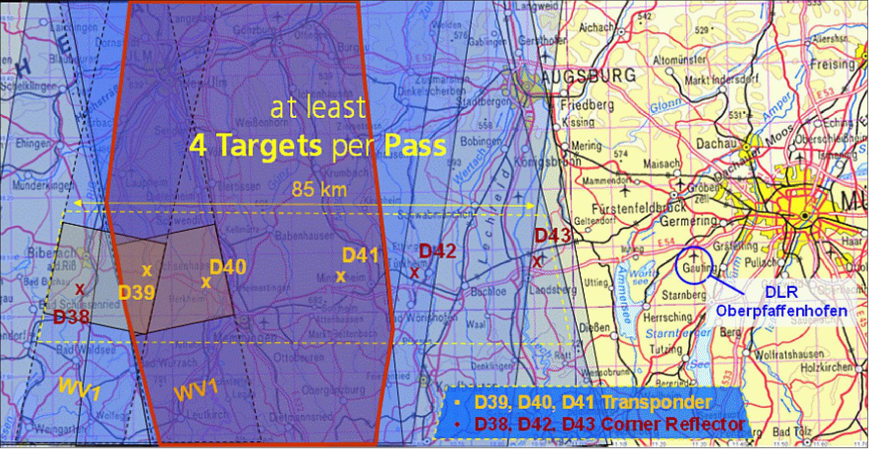
Figure 70: Coverage of Sentinel-1A for all beams being selected for in-flight measurements (SM1, SM2, IW1, EW3, IW3, SM5, WV1) across the DLR calibration field deployed in South Germany (image credit: DLR)
Hence, the test site shown in Figure 85, composed of three transponders and three corner reflectors, enclosing an area of about 85 km x 20 km, is sufficient to cope with the tight requirements of commissioning Sentinel-1A, i.e all measurements required for calibrating the whole Sentinel-1A system can be performed within the commissioning phase of three months.
Ground Segment
The ground segment is composed of the CGS (Core Ground Segment), the” Collaborative Ground Segment” and the Copernicus contributing missions' ground segments.
The Core ground segment monitors and controls the Sentinels spacecraft, ensures the measurement data acquisition, processing, archiving and dissemination to the final users. In addition, it is responsible for performing conflict-free mission planning according to a predefined operational scenario, and it ensures the quality of the data products and the performance of the space borne sensors by continuous monitoring, calibration and validation activities, guaranteeing the overall performance of the mission. 132)
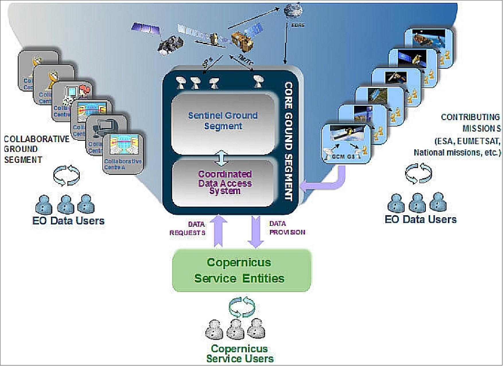
Figure 71: Copernicus Ground Segment Architecture (image credit: ESA)
The Copernicus Ground Segment is complemented by the Sentinel Collaborative Ground Segment, which was introduced with the aim of exploiting the Sentinel missions even further. This entails additional elements for specialized solutions in different technological areas such as data acquisition, complementary production and dissemination, innovative tools and applications, and complementary support to calibration & validation activities.
For Copernicus operations, ESA has defined the concept and architecture for the Copernicus Core ground segment, consisting of a FOS (Flight Operations System) and a PDGS (Payload Data Ground Segment). Whereas the flight operations and the mission control of Sentinel-1 and -2 is performed by ESOC (ESA's European Space Operations Center in Darmstadt, Germany), the operations of Sentinel-3 and the Sentinel-4/-5 attached payloads to meteorological satellites is performed by EUMETSAT.
The EC (European Commission), supported by its agencies, is in charge to implement the Copernicus Services. The Commission is defined to be the owner and financing organization of Copernicus. The technical implementation is granted to other European organizations, namely ESA, EUMETSAT, EEA (European Environment Agency), ECMWF (European Centre for Medium-Range Weather Forecasts) and others. - Complemented by ESA programs and national contributions, ESA has the responsibility to build and operate a dedicated space segment (Sentinels) and the ground segment of Copernicus. 133)
The EC has also defined an overall Copernicus data policy, declaring the Sentinel mission data free and open. 134) This decision is reflecting the experience made with similar missions in the US (e.g. Landsat) and the new possibilities of the Internet. It will stimulate the use of Earth observation data, but also may challenge commercial suppliers, selling data similar to those of the Sentinels. The Copernicus data policy is also based on the European INSPIRE (Infrastructure for Spatial Information in the European Community) directive, which harmonizes the policy and electronic access to geographic information within Europe.
The majority of the Earth observation data for these services will come from a fleet of dedicated Copernicus satellites: the Sentinels. The features of the Copernicus Sentinel missions are depicted in Table 12. The series of satellites guarantees continuity of the ERS/ENVISAT missions and adds further features and parameters. Moreover, always two Sentinels of each series should be in orbit at any time, increasing the coverage for many applications. Applications and services will also benefit from a supply from other European national and commercial GMES Contributing Missions (GCM), managed in Copernicus by the ESA GSCDA (GMES Space Component Data Access) system.
Copernicus Mission | Launch | Sensor complement | Objective |
Sentinel-1 | 2014 | C-SAR (C-band SAR) | ERS/ENVISAT SAR data continuity for Land and Ocean surveillance; interferometry |
Sentinel-2 | 2014 | MSI (Multispectral Instrument) | Deliver high resolution optical information of all land-masses of the Earth, complementing e.g. Landsat & SPOT series. |
Sentinel-3 | 2016 | OLCI (Ocean and Land Color Instrument) SLSTR (Sea and Land Surface Temp. Radiometer) SRAL (Ku/C-band Radar Altimeter) MWR (Micro-Wave Radiometer) | Global daily land and sea parameter observation POD (Precise Orbit Determination) |
Sentinel-4 (on MTG in GEO) | 2019 | UVN (UV-VIS-NIR) instrument | Monitoring of air quality, stratospheric ozone, solar radiation, and climate monitoring. |
Sentinel-5 (on MetOp SG in LEO) | 2020 | UVNS (UV-VIS-NIR-SWIR) instrument | Atmospheric composition, cloud and aerosol for air quality and climate applications |
Sentinel-5P (Precursor) | 2016 | TROPOMI (Tropospheric Monitoring Instrument) | Atmospheric composition, cloud and aerosol for air quality and climate applications |
The management of the payload data from the Sentinel missions is performed by the CGS (Core Ground Segment) defined by ESA. The CGS consists of a series of X-band data acquisition stations, which will capture all global Sentinel-1/-2/-3 mission data (Sentinel-4/-5 will use dedicated EUMETSAT data acquisition facilities for its next generation geostationary and polar orbiting satellites). These stations are designed for dumping all data recorded on the satellites on-board data recorders, as well as generating near real time products (1-3h after sensing) directly at the stations. The PDGS will also make use of the EDRS (European Data Relay Satellite). This PPP (Public Private Partnership) between ESA and ASTRIUM GmbH, operates a communication payload on two geostationary satellites. The primary link between the Sentinels and the geostationary satellites is a LCT (Laser Communication Terminal), built by Tesat Space, Backnang, Germany and provided as contribution-in-kind by Germany to the Sentinel-1 and -2 satellite series. The downlink from the geostationary satellites is performed via Ka-band to dedicated stations and to user terminals (Ref. 133). 135)
The acquired mission data is then transferred to Sentinel PACs (Processing and Archiving Centers). The PACs are designed to take specifically care for a certain Sentinel/instrument project. For security and redundancy reasons, each Sentinel data set is hosted by two PACs (EUMETSAT is assigned to act as the second PAC for the Sentinel-3 mission data). The PACs generate systematically base level products from all acquired data, archive them in a mission archive and electronically distribute them to the Copernicus users.
The products and performance of each Sentinel is monitored by MPCs (Mission Performance Centers). The entire data flow is managed by a PDMC (Payload Data Management Center), hosted by ESA at ESRIN, Frascati, Italy. The transport and circulation of the data is performed via terrestrial networks. The GMES WAN therefore connects all PDGS elements with links, having appropriate bandwidth.
In 2011, ESA started a series of procurement actions to select European providers to offer their facilities for the set-up and operations of the PDGS elements. Figure 87 displays the structure of the PDGS and the outcome of the selection of the providers.
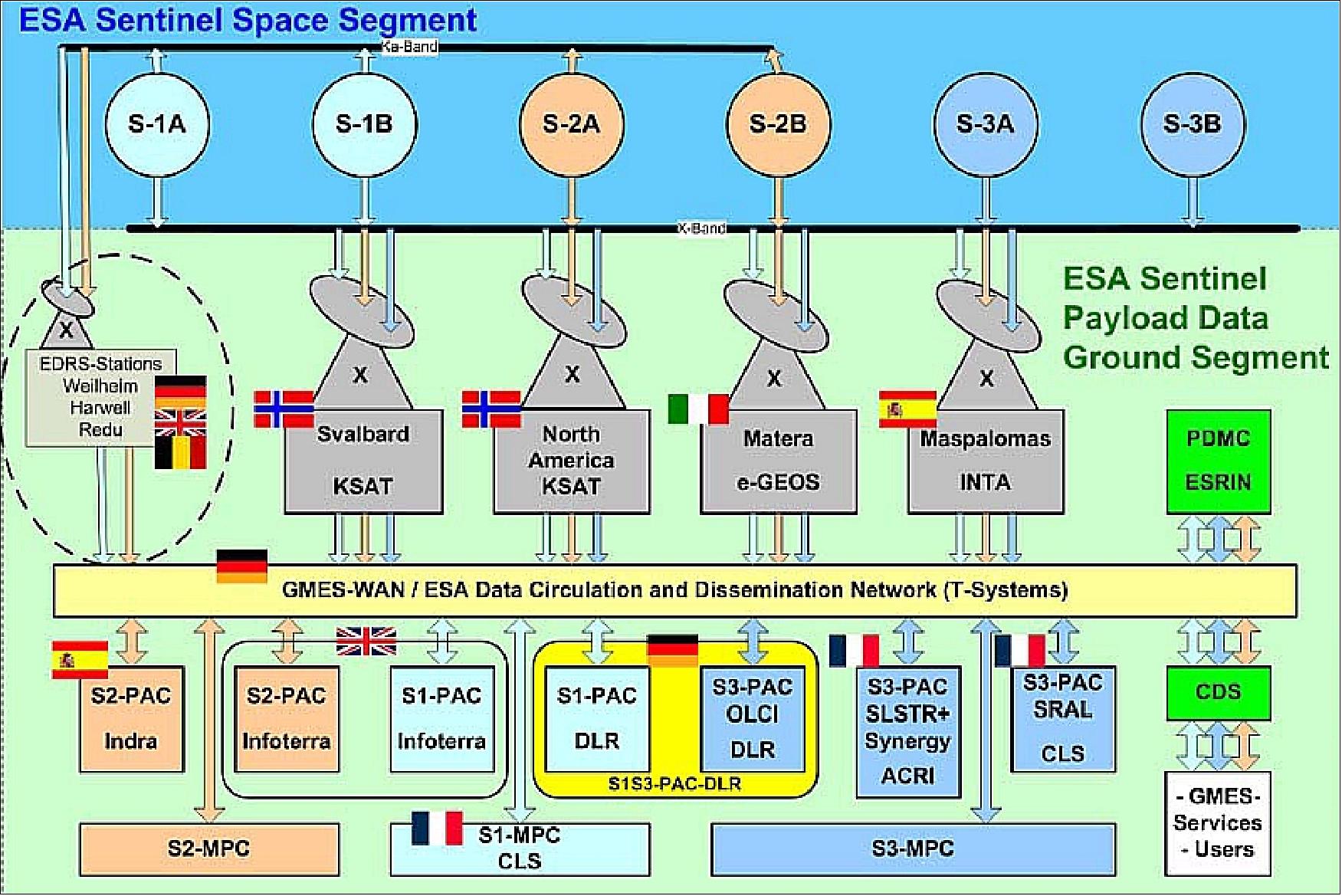
Figure 72: Overall structure of Copernicus Payload Data Ground Segment for Sentinels-1 to -3 (Status May 2013), image credit: ESA (Ref. 133)
Within this competitive selection process, ESA has awarded the DLR/DFD (German Remote Sensing Data Center) with the set-up and operations of the PACs for Sentinel-1 and Sentinel-3 (OLCI part). T-Systems, Germany, is assisting DLR in the network parts of the PACs. In addition and under separate procurement, DFD designs, builds and operates the payload data ground segment) for the Sentinel-5 Precursor mission.
High-level tasks of the DLR Sentinel PAC are:
- receive Sentinel data from CGSs via the GMES WAN
- ingest these data into the STA (Short-Term Archive) and MTA (Mid-Term Archive) of the Sentinel PGDS
- ingest these data in a LTA (Long-Term Archive) for a period of more than 7 years
- perform consolidation and re-assembly of level-0 data received from CGS facilities
- perform systematic and request-driven processing of Sentinel data to higher-level products
- host Sentinel data products within a layered architecture of on-line dissemination elements that will facilitate the direct access of end-users via public networks
- share and exchange any locally processed data with a 2nd partner PAC for the purpose of redundancy.
According to the GSC (GMES Space Component) operations concept, the Sentinel PDGS will become operationally embedded in the GSCDA (GMES Space Component Data Access) System that ESA implements in support of data access to GMES/Copernicus Service Projects and their users.
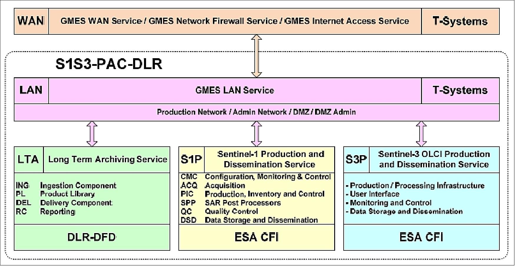
Figure 73: Overall structure of the Sentinel-1 (S1) and Sentinel-3-OLCI PACs at DFD in Oberpfaffenhofen (image credit: DLR)
Sentinel-5P: The Sentinel-5 Precursor satellite will deliver a key set of atmospheric composition, cloud and aerosol data products for air quality and climate applications. The sensing instrument TROPOMI together with the operational level 1 and level 2 processors will bring a significant improvement in the precision as well as temporal and spatial resolution of derived atmospheric constituents. Sentinel-5 Precursor is planned for launch in 2016.
For the Sentinel-5P mission, DLR/DFD was selected by ESA for the development and operation of the entire PDGS (Payload Data Ground Segment), which covers the whole chain of payload data handling on ground: data reception, processing, archiving, near-real-time and offline delivery to end users. In addition, DLR/IMF (Institut für Methodik der Fernerkundung - Remote Sensing Technology Institute) was selected for the development of retrieval algorithms and operational processors for a number of key atmospheric trace gases and cloud products.
Sentinel-5P will continue the strong DFD heritage on development/operations of processors and ground segments for atmospheric missions started with GOME-1/ERS-2, SCIAMACHY/ENVISAT, and GOME-2 on the MetOp series. The Sentinel-5P PDGS - as well as the LTA for Sentinel-1 and Sentinel 3 OCLI - will be based on the DFD development of DIMS (Data and Information Management System). DIMS will be configured for the Sentinel 5P workflows and mission specific extensions for the demanding throughput and storage requirements (Ref. 133).
In summary, DLR/DFD is involved in the Core and collaborative ground segment of the Copernicus program. It has been developing PDGS (Payload Data Ground Segment) elements and will operate PACs (Processing and Archiving Centers) for Sentinels and national data acquisition stations, both in X-band and using EDRS acquisition services.
Sentinel-1 FOS (Flight Operations Segment)
The main responsibilities of the FOS at ESA encompass satellite monitoring and control, including execution of all platform activities and the commanding of the payload schedules. The principal components of the FOS are (Ref. 135): 136)
1) The Ground Station and Communications Network, which performs TT&C (Telemetry, Tracking and Commanding) operations within the S-band frequency. A single S-band ground station will be used throughout all mission phases, complemented by additional TT&C stations as launch and early operations (LEOP) and backup stations.
2) The FOCC (Flight Operations Control Center), which includes:
• the Sentinel Mission Control System, which supports telecommand coding and transfer and housekeeping telemetry (HKTM) data archiving and processing
• the Sentinel Mission Planning System which supports command request handling, the planning and scheduling of satellite operations and the scheduling of payload operations as prepared by the PDGS Mission Planning System
• the specific Sentinel Satellite Simulators, which support procedure validation, operator training and the simulation campaign before each major phase of the mission
• the Sentinel Flight Dynamics System, which supports all activities related to attitude and orbit determination and prediction, the preparation of slew and orbit maneuvers, satellite dynamics evaluation and navigation
• The Sentinel Key Management Facilities, which support the management of the telecommand security functions.
3) A General Purpose Communication Network, which provides the services for exchanging data with any other external system during all mission phases.
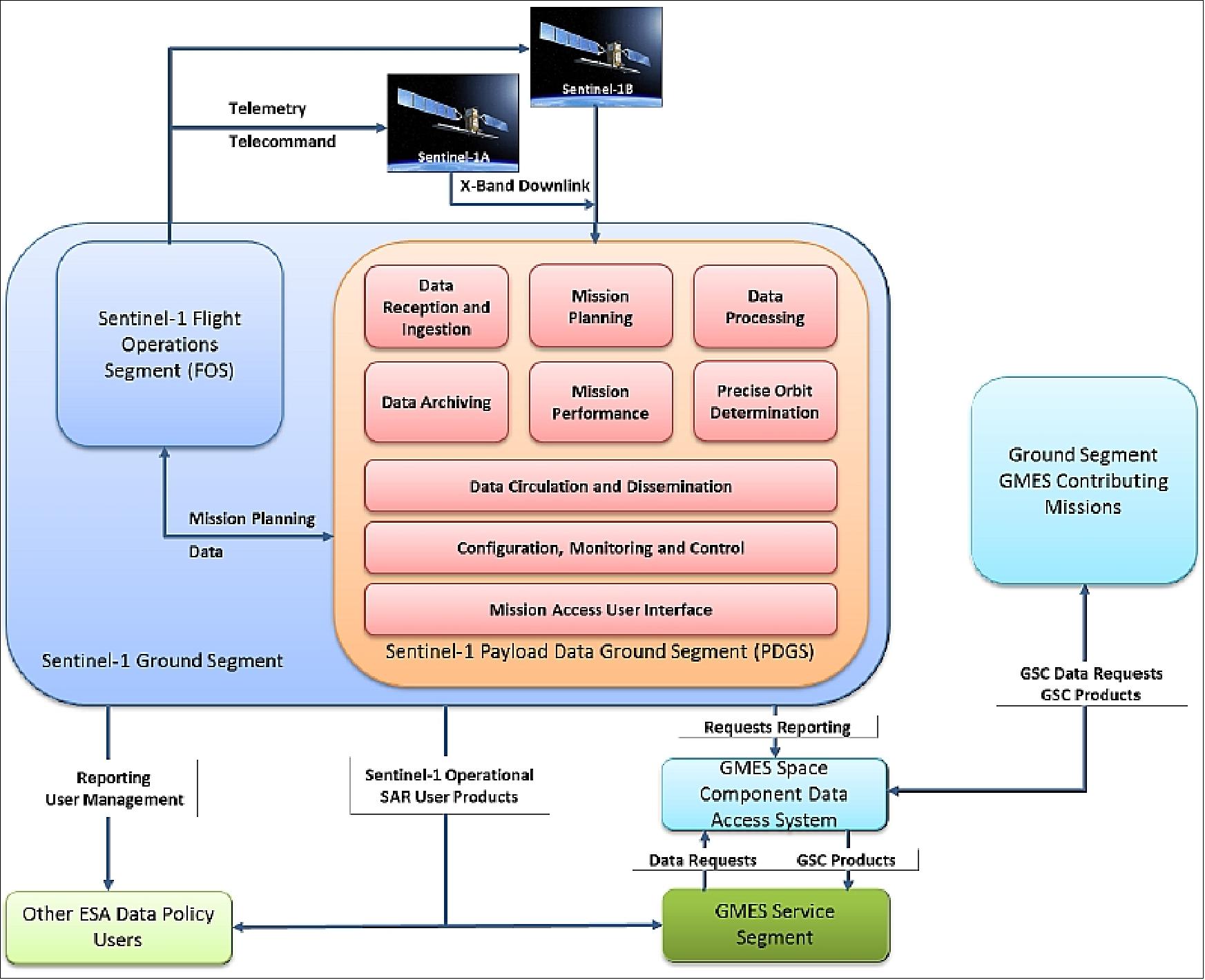
Figure 74: Simplified view of the Sentinel-1 Ground Segment (image credit: Astrium SAS)
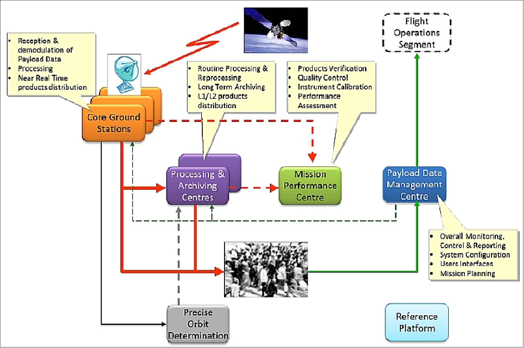
Figure 75: Overall Layout of the Sentinel-1 Core PDGS (image credit: Astrium SAS)
The selected geographical locations and operators for the Sentinel-1 PDGS centers are (Ref. 135):
• KSAT for X-band reception (CGS) in Svalbard (Norway) and Alaska
• INTA for X-band reception in Maspalomas (Spain)
• E-Geos for X-band reception in Matera (Italy)
• Astrium Services for the PAC (Processing and Archiving Center) in Farnborough (UK)
• DLR for the PAC in Oberpfaffenhofen (Germany)
• CLS for the MPC (Mission Performance Center) operations in Brest (France).
• PDMC (Payload Data Management Center) will be located at ESRIN and be operated by the European Space Agency.
• The POD (Precise Orbit Determination) service will be provided by GMV (Spain).
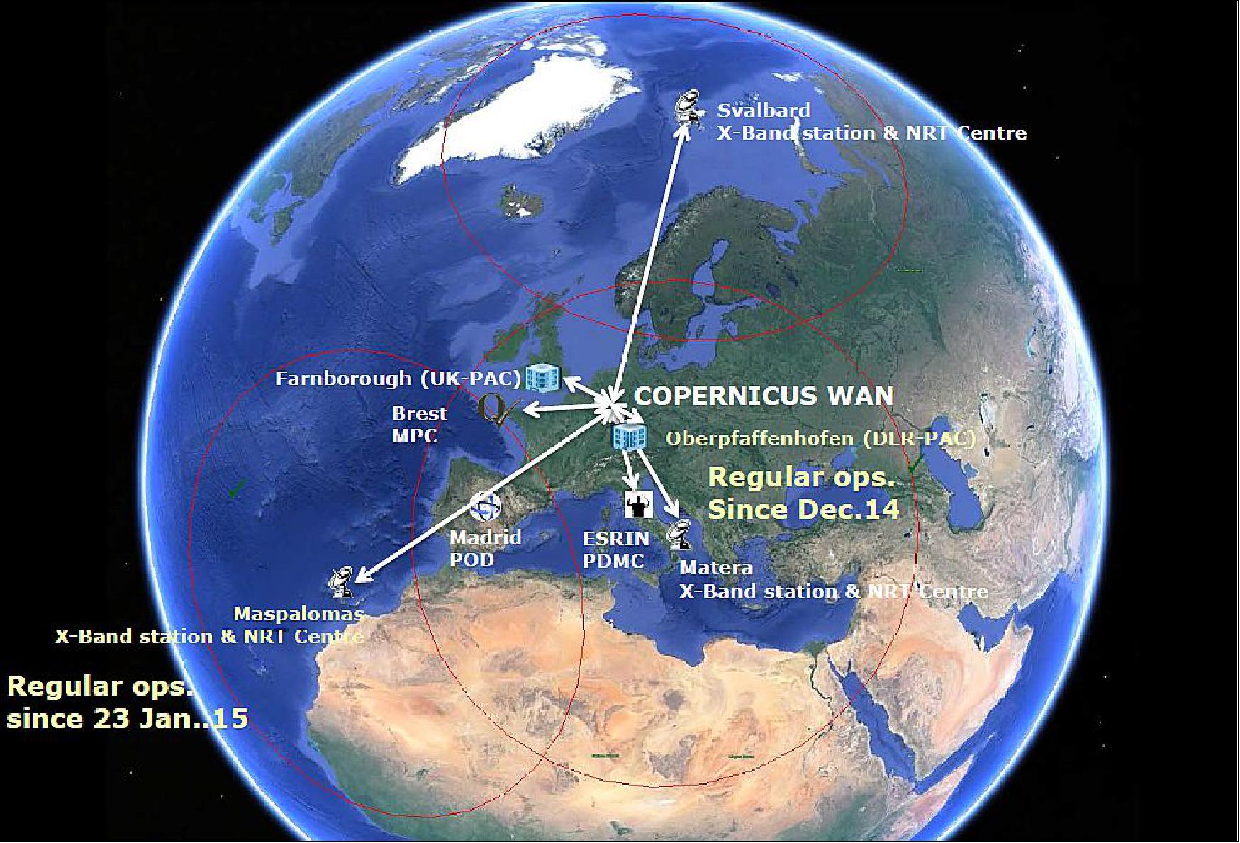
CPOD (Copernicus Precise Orbit Determination) Service
The CPOD service is part of the PDGS (Payload Data Ground Segment) of the Sentinel missions. A GMV-led consortium of Spain is operating the CPOD being in charge of generating precise orbital products and auxiliary data files for their use as part of the processing chains of the respective Sentinel PDGS. 138)
Figure 92 shows the different elements that interact with the CPOD service. On top we have the Sentinels satellites, all of them with two GPS Receivers on-board (Sentinel-3 also has a LRR and DORIS). The raw L0 data is downloaded at least once per orbit to one of the Ground Stations used (particularly Svalbard, but also Maspalomas and Matera are used). The raw L0 data that contains the GPS and attitude data is circulated to the Sentinels PDGS and from there it is made available to the CPOD Service Center, which will generate orbital products with different timelines.
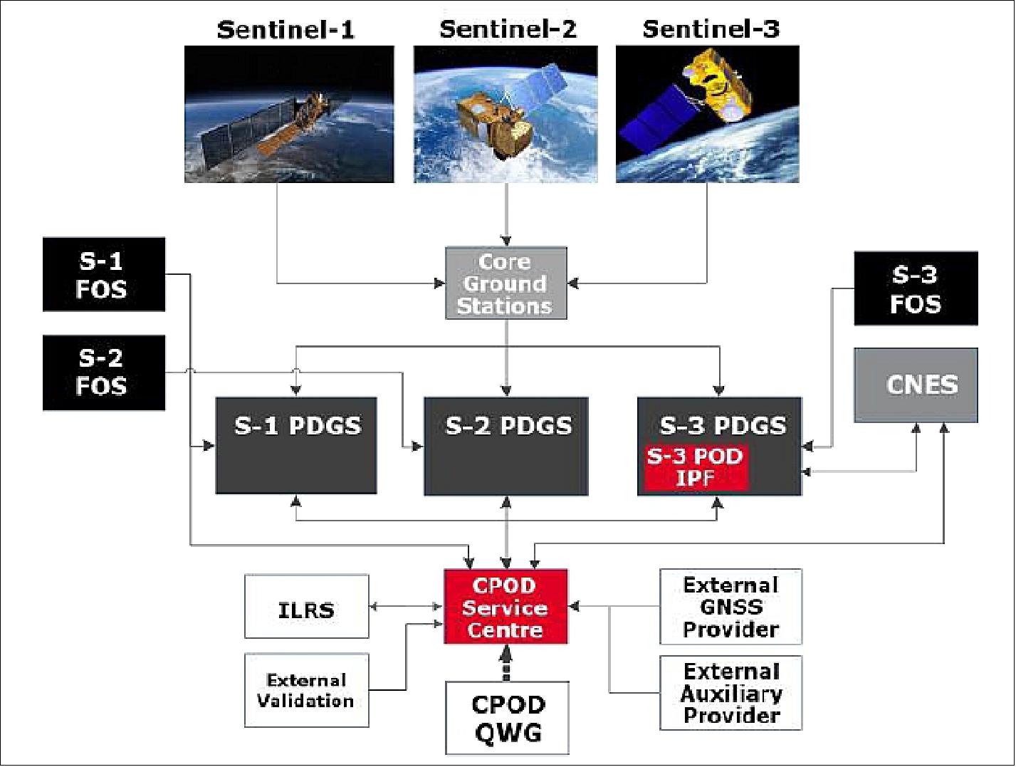
Figure 77: Overview of the CPOD service elements (image credit: GMV, ESA)
The first three Sentinel missions require orbital products in NRT (Near Real Time), with latencies as low as 30 minutes, in STC (Short Time Critical), with latencies of 1.5 days and in NTC (Non-time Critical) with latencies of 20-30 days. The accuracy requirements are very challenging, targeting 5 cm in 3D for Sentinel-1 and 2-3 cm in radial direction for Sentinel-3.
Mission | Orbit Product | Product Category | Latency Requirement | Position Accuracy (RMS orbit) |
S-1 | NRT | Restituted | Within 3 hours (from the reception of GNSS data) | < 10 cm (2D) |
S-2 | NRT | Restituted | 90 minutes before Sentinel-2 A/B ANX is crossed | < 10 m (2D) 3-sigma |
S-2 | NRT | Restituted | Within 30 minutes (from the reception of GNSS data) | < 3 m (3D) 3-sigma |
S-3 | NRT | Restituted | Within 30 minutes (from the reception of GNSS data) | 10 cm threshold with a target of 8 cm (radial) |
S-3 | STC | Preliminary | Within 1,5 days (36 hr) | 4 cm threshold with a target of 3 cm (radial) |
S-1 | NTC | Precise | Within 20 days | 5 cm (3D) |
S-3 | NTC | Precise | Within 28 days (i.e. 2 days before NTC science product delivery) | 3 cm threshold with a target of 2 cm (radial) |
Table 12: Summary of timeliness and accuracy requirements 139)
The CPOD Service has been developed and it is being operated by a GMV-led consortium with a system running at GMV premises to provide orbital products for the Sentinel missions with different timeliness: NRT, STC , NTC and reprocessing REP. Additionally the Sentinel-3 POD IPF (Instrument Processing Facility), a software package developed as part of the CPOD Service, will run at the Sentinel-3 PDGS (on both, the Marine Center and Core Ground Station) generating NRT orbital products for the Sentinel-3 mission.
The accuracy of the orbital products is assessed by several external validation institutions, which are a part of the Copernicus POD QWG (Quality Working Group). The purpose of the Copernicus POD QWG is to monitor the performance of the operational POD products (both the orbit products and the input tracking data) and to define potential and future enhancements to the orbit solutions.
The different Sentinel FOSs (Flight Operation Segments) provide orbital products (restituted and predicted) plus maneuver and mass history information. CNES provides orbital products and DORIS data for Sentinel-3, and it receives GPS RINEX (Receiver Independent Exchange Format) files from the CPOD Service Center.
Veripos Ltd is the source of accurate GPS orbits and clocks for NRT and STC latencies and IGS for NTC and REP latencies. The CPOD also has an in-house back-up of Veripos based on magicGNSS, which provides NRT GPS orbits and clocks. For Sentinel-3, ILRS (International Laser Ranging Service) and DORIS data will also be used. Finally, the CPOD Service interacts with the CPOD QWG and several external validation centers.
The Copernicus POD Service has been developed and it is operated by GMV. However, it interacts with different entities (public and private) that act as clients, users and subcontractors.
Following are the current main members of the Copernicus POD Service
- ESA/ESRIN (European Space Research Institute) Frascati, Italy. This center leads the development of the different PGDSs, and in particular, the Sentinel-1 and -2 PDGS are located here.
- ESA/ESOC (European Space Operation Center), Darmstadt, Germany. This center hosts the FOS (Flight Operations Segment) of Sentinel-1, -2, and -3 missions during the commissioning phase and also during the Routine Operation phase except for Sentinel-3 mission, which is handed over to EUMETSAT.
- EUMETSAT (European Organization for the Exploitation of Meteorological Satellites), Darmstadt, Germany. This center hosts the FOS ( Flight Operations Segment) of Sentinel-3 mission during the Routine Operation Phase, and also the so-called Marine Center PDGS of Sentinel-3.
- CNES (Centre National d'Études Spatiales), Toulouse, France provides accurate orbits and platform data files for the Sentinel-3 mission. CNES has also contributed with the DORIS instrument, and as so, it also provides RINEX DORIS files to the Copernicus POD Service.
- GMV Innovating Solutions is the prime of the Copernicus POD Service. It has developed and it is operating the Service from its headquarters in Tres Cantos, near Madrid (Spain). It is responsible also of the overall management and the evolutions of the system.
- POSITIM UG provides expertise in the LEO POD field, prototypes improvements in algorithms and manages, on behalf of ESA/GMV, the Quality Working Group.
- DLR (Deutsches Zentrum für Luft- und Raumfahrt) Oberpfaffenhofen, Germany provides expertise in the LEO POD and GNSS fields. Additionally, it contributes with orbital products for external validation of products.
- TUM (Technische Universität München) provides expertise in the LEO POD field. Additionally, it contributes with orbital products for external validation of products.
- AIUB (Astronomisches Institut, Universität Bern), Bern, Switzerland contributes with orbital products for external validation of products.
- TU Delft (Technische Universiteit Delft), Delft, The Netherlands contributes with orbital products for external validation of products.
- VERIPOS Ltd, Aberdeen, UK is the provider of accurate GPS orbits and clocks in NRT and STC timeliness for it use in the GNSS POD processing.
There are two places where the operational orbits are computed. The so-called CPOD Service Center, located in GMV's premises, is in charge of computing all orbital products of Sentinel-1 and -2 and all STC and NTC products of Sentinel-3. The Sentinel-3 POD IPF (Instrument Processing Facility) is in charge of computing the Sentinel-3 NRT orbital products and it will be running at two locations, the Marine center (located in EUMETSAT, Darmstadt) and the Core Ground Station (located in Svalbard).
Orbital Accuracy Results
• Sentinel-1A was launched on April 3, 2014. After 6 months of commissioning, the CPOD Service started the ROP (Routine Operation Phase) in October 2014. Since then, every four months the quality of the service is assessed, including the accuracy of the orbital products. For this, a specific period is selected for re-processing by the external validation institutions (i.e. AIUB, DLR, ESOC, TU Delft and TUM). This exercise has been performed twice since the beginning of the ROP phase.
• Sentinel-2A was launched on June, 23, 2015. The commissioning phase is expected to finish by mid/end October 2015, so the ROP (Routine Operation Phase) is expected to begin in November 2015. During the commissioning phase the orbit accuracy has been assessed by the same means used with Sentinel-1A, selecting a period to be re-processed by the external validation institutions (Ref. 138).
In the case of Sentinel-1A, the institutions compute offline accurate orbits and provide them to GMV for cross-comparison. It has been shown that systematically the accuracy requirements are fulfilled without major problems. Figure 93 shows the results of the last comparison campaign of January 2016; it shows the 3D RMS per day, during 10 days in January 2016, between the operational Sentinel-1 NTC solution (CPOD) and the daily solutions provided by each institution. Additionally, there is a combined solution (COMB) computed as a weighted average of all individual solutions. It can be seen that the differences are systematically below the required 5 cm (Ref. 139).
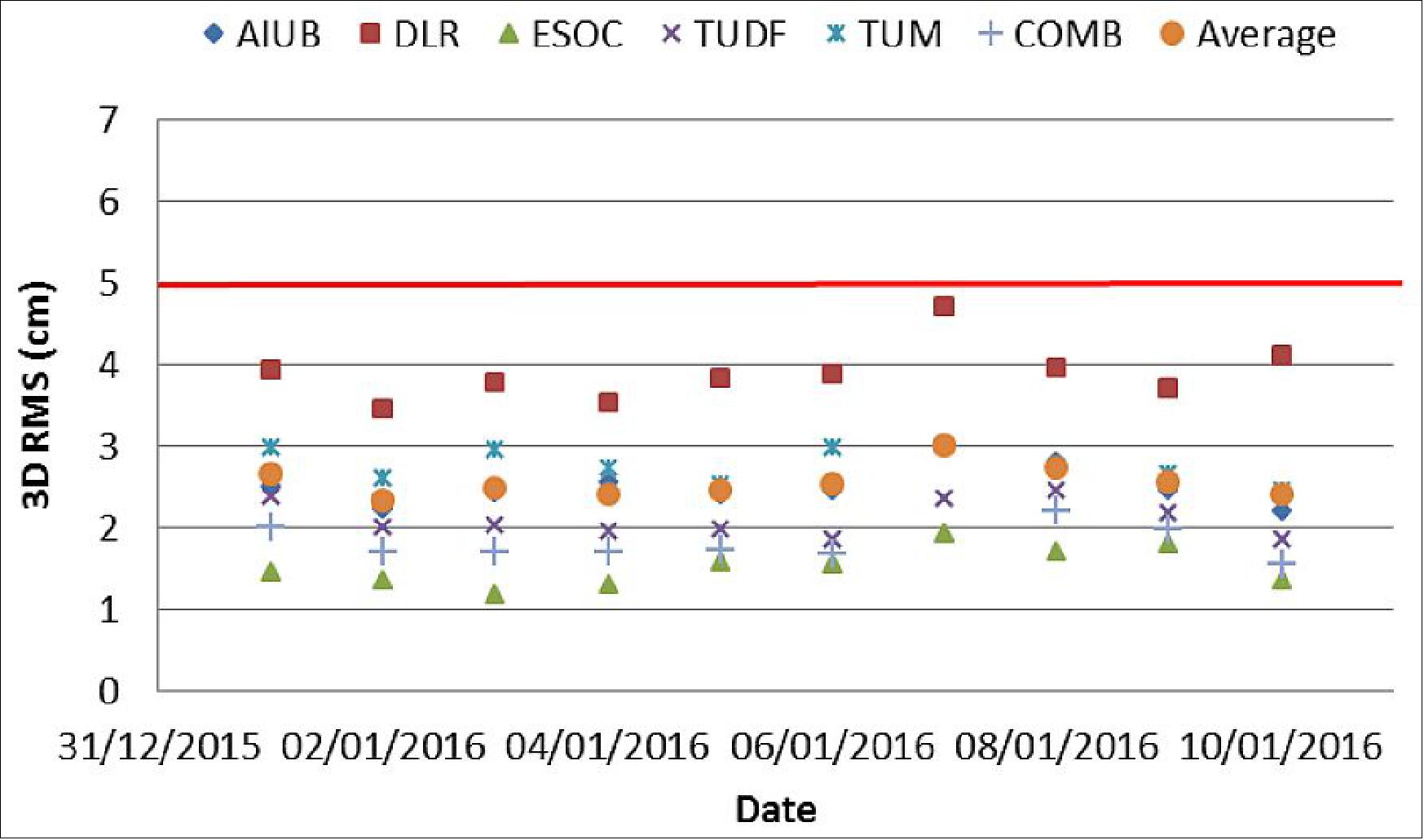
Figure 78: Sentinel-1A orbit comparisons (3D RMS; cm) between CPOD and external solutions; red line is threshold (image credit: GMV)
In addition, all NRT and NTC products are compared routinely against an offline ESOC solution (which used the same POD SW, NAPEOS, but of a different version and using different configuration and inputs). The following plots (Figures 94 and 95) show the differences concerning ESOC from October 2015 to January 2016, where it can be seen that systematically the differences are well below the threshold. The cases above the threshold are typically due to maneuvers and data gaps.
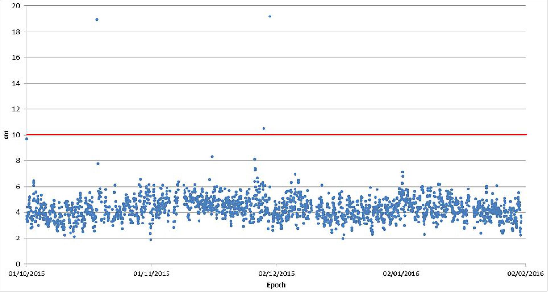
Figure 79: Sentinel-1A Restituted Orbital Product vs. ESOC (2D RMS) from 1st October 2015 until 31st January 2016 (image credit: GMV)
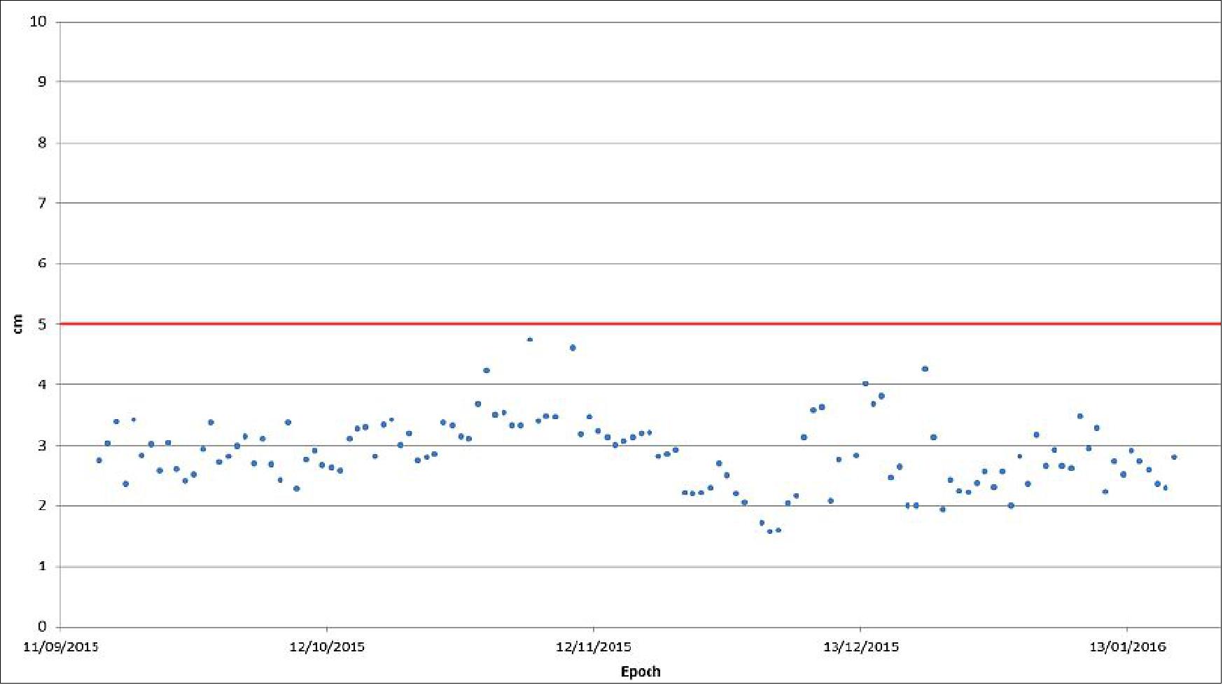
Figure 80: Sentinel-1A Precise Orbital Product vs. ESOC (3D RMS) from 1st October 2015 to 31st January 2016 (image credit: GMV)
In the case of Sentinel-2A, the accuracy results are similar to those of Sentinel-1A.
Figure 96 shows the results of the last comparison campaign of January 2016; it shows the 3D RMS per day, during 10 days in January 2016, between the operational Sentinel-2 NTC solution (CPOD) and the daily solutions provided by each institution. Additionally there is a combined solution (COMB) computed as a weighted average of all individual solution. It can be seen that the differences are systematically below 5 cm, like in the case of Sentinel-1A.
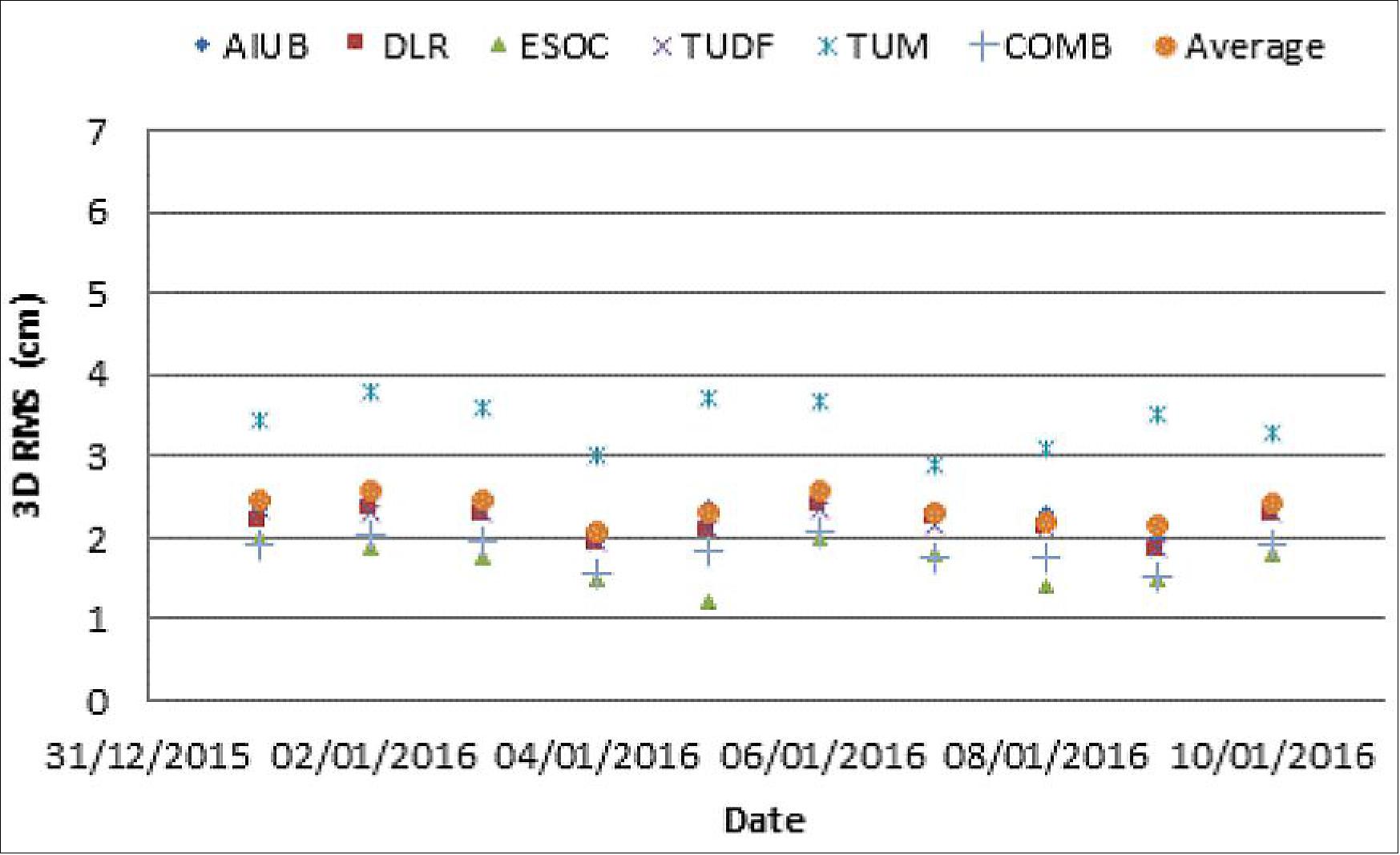
Copernicus / Sentinels EDRS System Operations
EDRS (European Data Relay Satellite) will provide a data relay service to Sentinel-1 and -2 and initially is required to support 4 Sentinels simultaneously. Each Sentinel will communicate with a geostationary EDRS satellite via an optical laser link. The EDRS GEO satellite will relay the data to the ground via a Ka-band link. Optionally, the Ka-band downlink is planned to be encrypted, e.g. in support to security relevant applications. Two EDRS geo-stationary satellites are currently planned, providing in-orbit redundancy to the Sentinels. 140)
EDRS will provide the same data at the ground station interface as is available at the input to the OCP (Optical Communications Payload) on-board the satellites, using the same interface as the X-band downlink. The EDRS transparently adapts the Sentinels data rate and format to the internal EDRS rate and formats, e.g. EDRS operates at bit rates of 600 Mbit/s and higher.
With EDRS, instrument data is directly down-linked via data relay to processing and archiving centers, while other data continues to be received at X-band ground stations. The allocation of the data to downlink via X-band or EDRS is handled as part of the Sentinel mission planning system and will take into account the visibility zones of the X-band station network and requirements such as timeliness of data.
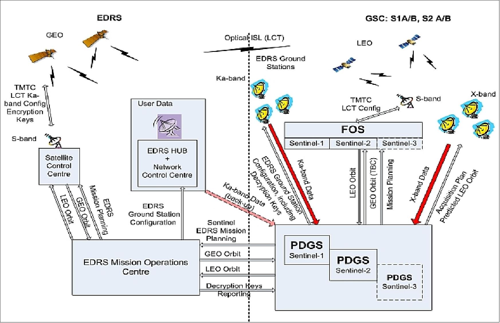
Copernicus / Sentinel Data Policy
The principles of the Sentinel data policy, jointly established by EC and ESA, are based on a full and open access to the data:
• anybody can access acquired Sentinel data; in particular, no difference is made between public, commercial and scientific use and in between European or non-European users (on a best effort basis, taking into consideration technical and financial constraints);
• the licenses for the Sentinel data itself are free of charge;
• the Sentinel data will be made available to the users via a "generic" online access mode, free of charge. "Generic" online access is subject to a user registration process and the acceptation of generic terms and conditions;
Following registration, the user will have the possibility to immediately download a test data set that simulates the data products that will be generated by Sentinel-1. Following launch, registered users will be granted early access to Sentinel-1 data samples, even before the full operational qualification of the products is completed.
Registration is open to all users via simple on-line self-registration accessible via the Sentinel Data Hub. 141)
• additional access modes and the delivery of additional products will be tailored to specific user needs, and therefore subject to tailored conditions;
• in the event security restrictions apply to specific Sentinel data affecting data availability or timeliness, specific operational procedures will be activated.
ESA Member States approved these principles in September 2009. 142) 143) 144) 145) 146)
Sentinel-1 Operational Products
• Level-0 products: Compressed, unprocessed instrument source packets, with additional annotations and auxiliary information to support the processing. 147)
• Level-1 products:
- Level-1 Slant-Range Single-Look Complex Products (SLC): Focused data in slant-range geometry, single look, containing phase and amplitude information.
- Level-1 Ground Range Detected Geo-referenced Products (GRD): Focused data projected to ground range, detected and multi-looked. Data is projected to ground range using an Earth ellipsoid model, maintaining the original satellite path direction and including complete geo-reference information.
• Level-2 Ocean products: Ocean wind field, swell wave spectra and surface currents information as derived from SAR data.
Product generation policy | Product type | Access mode | Timeliness |
Systematic Global (for all acquired data) | L0 L1 GRD L2 Ocean | Subscription | 3 hours from observation (NRT data) 24 hours from observation (standard) |
Free online access from archive | > 24 hours from observation | ||
Systematic Regional (for a subset of acquired data) | L1 SLC (Single-Look Complex) | Subscription | 3 hours from observation (NRT data) 24 hours from observation (standard) |
Free online access from archive | > 24 hours from observation | ||
Systematic Local (for a subset of data acquired over ocean in the visibility of a Core Ground Station) | L0 | Subscription | < 1 hour from observation |
Acquisition mode | Product type | Resolution class | Resolution (range x azi) (m) | Pixel spacing (range x azi) (m) | No of looks (range x azi) | ENL |
SM (Stripmap Mode) | SLC | - | 1.7 x 4.3 to 3.6 x 4.9 | 1.5 x 3.6 to 3.1 x 4.1 | 1 x 1 | 1 |
GRD | FR | 9 x 9 | 4 x 4 | 2 x 2 | 3.9 | |
HR | 23 x 23 | 10 x 10 | 6 x 6 | 34.4 | ||
MR | 84 x 84 | 40 x 40 | 22 x 22 | 464.7 | ||
IW (Interferometric Wide Swath) | SLC | - | 2.7 x 22 to 3.5 x 22 | 2.3 x 17.4 to 3 x 17.4 | 1 | 1 |
GRD | HR | 20 x 22 | 10 x 10 | 5 x 1 | 4.9 | |
MR | 88 x 89 | 40 x 40 | 22 x 5 | 105.7 | ||
EW (Extra Wide Swath) | SLC | - | 7.9 x 42 to 14.4 x 43 | 5.9 x 34.7 to 12.5 x 34.7 | 1 x 1 | 1 |
GRD | HR | 50 x 50 | 25 x 25 | 3 x 1 | 3 | |
MR | 93 x 87 | 40 x 40 | 6 x 2 | 12 | ||
WV (Water Vapor) | SLC | - | 2.0 x 4.8 and 3.1 x 4.8 | 1.7 x 4.1 and 2.7 x 4.1 | 1 x 1 | 1 |
GRD | MR | 52 x 51 | 25 x 25 | 13 x 13 | 139.7 |
Table 14: Planned operational ESA Sentinel-1 products - L1 characteristics 148)
• For GRD (Ground Range Detected) products, the resolution corresponds to the mid range value at mid orbit altitude, averaged over all swaths.
• For SLC (Slant-Range Single-Look Complex) products SM/IW/EW products, the resolution and pixel spacing are provided from lowest to highest incidence angle. For SLC WV products, the resolution and pixel spacing are provided for beams WV1and WV2.
• For SLC SM/IW/EW products, the resolution and pixel spacing are provided from lowest to highest incidence angle. For SLC WV products, the resolution and pixel spacing are provided for beams WV1and WV2.
Preparatory Campaigns
In the context of the Copernicus program, ESA is conducting several coordinated preparatory activities (studies, campaigns, etc.) to demonstrate/validate the observation concepts (as well as many other system aspects) that are being planned for the various Sentinel missions. The following campaigns are in particular dedicated in support of Sentinel-1 (and -2, AgriSAR) applications.
AgriSAR 2009
The AgriSAR 2009 campaign of ESA took place in April 2009. The objective is to evaluate how frequent multi-polarization acquisitions provided by Sentinel-1 will improve applications such as land-cover mapping and crop monitoring. To accomplish this ambitious task, ESA has asked MDA Geospatial Services to acquire multi-temporal, quad-polarization RADARSAT-2 imagery throughout the 2009 growing season over three test sites. The chosen sites are located in Flevoland in the Netherlands, Barrax in Spain and Indian Head in mid-west Canada.
In addition to the contribution from MDA Geospatial Services, the campaign included also several European and Canadian scientists to help with ground activities. These activities included the collection and analysis of information about land cover, crop type, crop condition and other parameters such as soil moisture. Of particular interest were the new algorithms and methods required to extract land-cover information from a dense temporal series of SAR images and follow how the crops develop. 149)
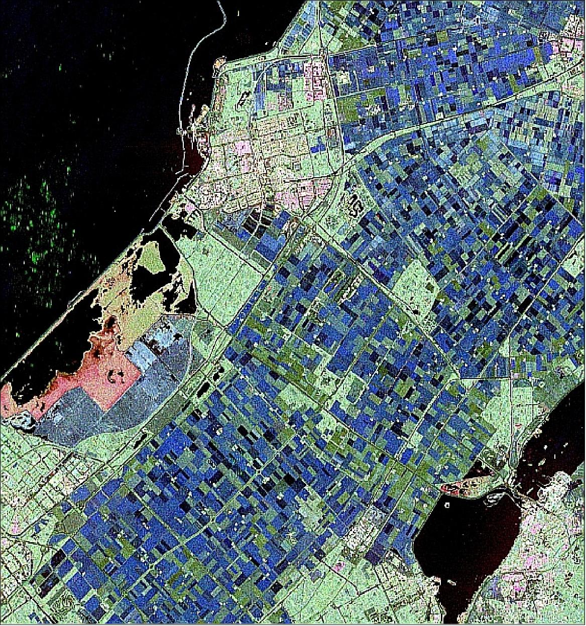
Figure 83: The color composite of a RADARSAT-2 polarimetric radar image acquired over the Flevoland test site in the Netherlands on April 4, 2009 (image credit: ESA)
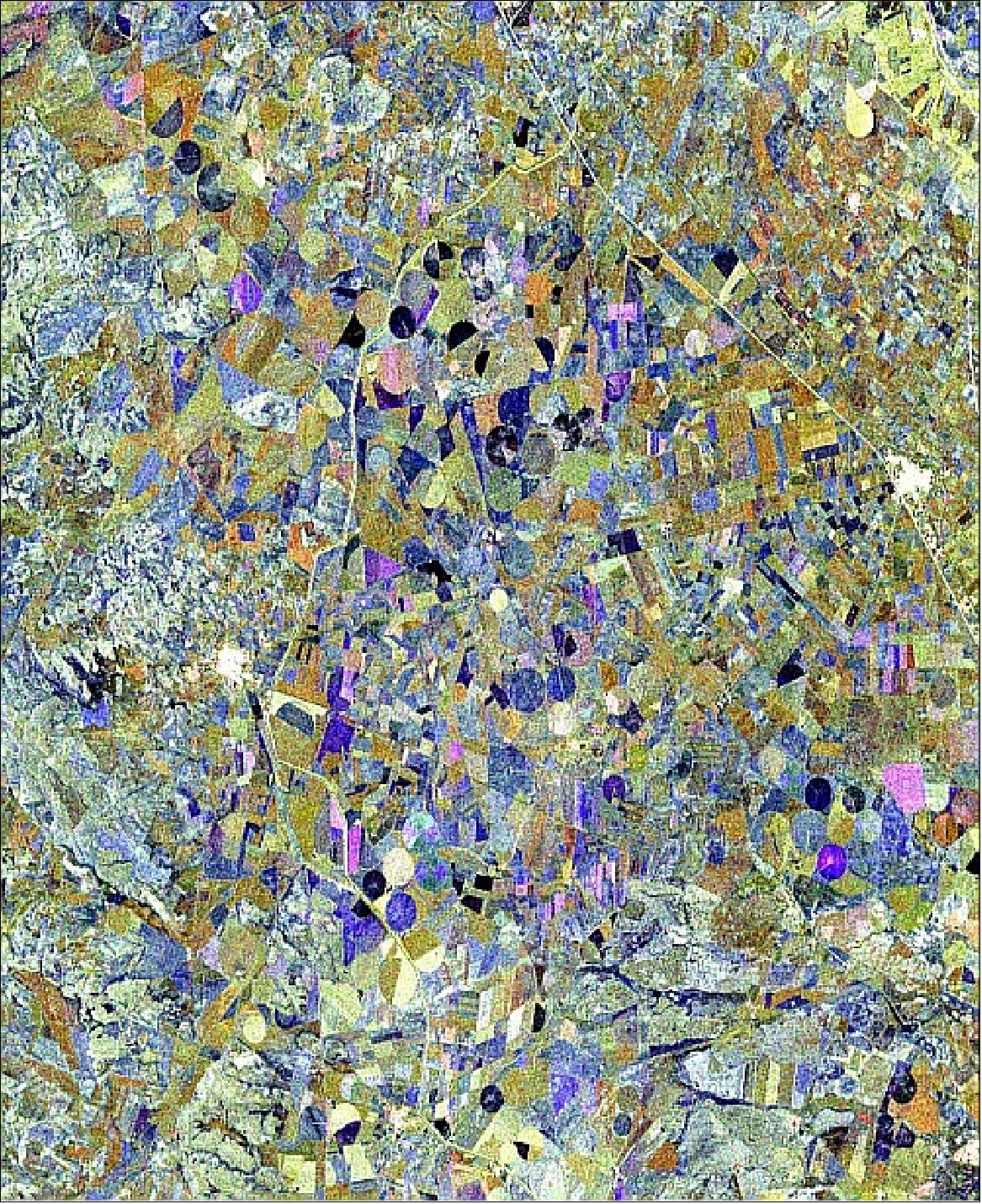
Figure 84: Polarimetric RADARSAT-2 SAR image of the Barrax test site in Spain on April 9, 2009 (image credit: ESA)
IceSAR 2007
The IceSAR airborne campaign (3 weeks in March 2007), which took place near Longyearbyen in Svalbard (Norway), was conducted by AWI (Alfred Wegner Institut), Bremerhaven, DLR/HR (Microwave and Radar Institute), and ESA. The radar configuration consisted of a C-band instrument with VV and VH polarizations, very similar to the future Sentinel-1 sensor. The C-band SAR was flown on the DO-228 aircraft of DLR (E-SAR instrument with C- and X-band capability). In addition, the Polar-2 aircraft of AWI was flown carrying the AWI infrared line scanner during the IceSAR campaign in coordination with the radar aircraft. 150) 151)
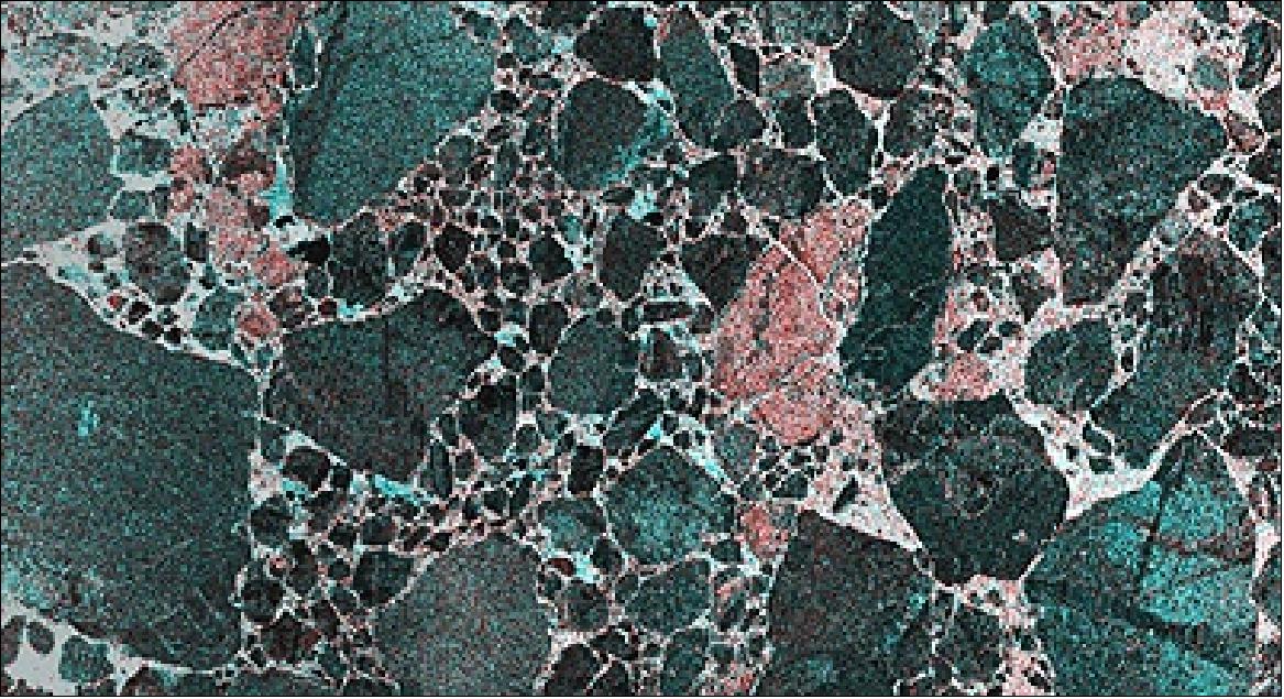
Figure 85: An airborne SAR sea-ice image taken over Storfjorden, Svalbard on March, 16, 2007 (image credit: ESA)
AgriSAR 2006
The AgriSAR campaign of ESA took place in the summer of 2006 (Apr. 18 - Aug. 2, 2006) - representing an ambitious large-scale attempt to assess the performance of the Sentinel-1 (C-band SAR) and Sentinel-2 (Optical Multispectral) for land applications. The campaign was unique in scope and scale representing frequent airborne SAR coverage during the entire crop-growing season, from sowing to harvest. 152) 153) 154)
The main test site was Demmin (Durable Environmental Multidisciplinary Monitoring Information Network), an agricultural site located in Mecklenburg-Vorpommern in North-East Germany, approximately 150 km north of Berlin. Main crop types in the area are winter wheat, barley, maize, rape and sugar beet. The DLR (German Aerospace Center) E-SAR system was flown over the Demmin test site more than 14 times between April and July. Weekly in-situ measurements were taken on the ground in selected fields throughout the same period.
In addition to SAR coverage, optical data using the Canadian CASI instrument from ITRES Research and the Spanish AHS from the National Institute for Aerospace Technology (INTA), were acquired during critical phases of the growing season in June and July. The June acquisitions were extended to include a forest and grassland site in the central Netherlands, used by the EU EAGLE project.
In total, over 15 research institutes from Germany, Spain, Italy, Belgium, The Netherlands, Britain, Canada and Denmark participated in the campaign.
References
1) “Copernicus: new name for European Earth Observation Programme,” European Commission Press Release, Dec. 12, 2012, URL: http://europa.eu/rapid/press-release_IP-12-1345_en.htm
2) M. W. J. Davidson, E. Attema, B. Rommen, N. Floury, L. Moreno Patricio, G. Lerini, “ESA Sentinel-1 SAR mission concept,” Proceedings of EUSAR 2006, Dresden, Germany, May 16-18, 2006
3) http://esamultimedia.esa.int/docs/GMES/ESA/3_coloc_Sentinel1_Status.pdf
4) E. Attema, P. Bargellini, P. Edwards, G. Levrini, S. Lokas, L. Moeller, B. Rosich-Tell, P. Secchi, R. Torres, M. Davidson, P. Snoeij, “Sentinel-1: The Radar Mission for GMES Operational Land and Sea Services,” ESA Bulletin, No 131, August 2007, pp. 10-17, URL: http://www.esa.int/esapub/bulletin/bulletin131/bul131a_attema.pdf
5) E. Attema, “Mission Requirements Document for the European Radar Observatory Sentinel-1,” July 7, 2005, URL: http://esamultimedia.esa.int/docs/GMES/GMES_SENT1_MRD_1-4_approved_version.pdf
6) M. Davidson, E. Attema, “Sentinel-1 SAR Mission Current Status,” 5th GSE Co-location Meeting, March 6-7, 2007, ESA/ESRIN, Frascati, Italy, URL: http://esamultimedia.esa.int/docs/GMES/ESA/3_coloc_Sentinel1_Status.pdf
7) Malcolm Davidson, Evert Attema, Laura Moreno Patricia, Guido Levrini, Bjorn Rommen, Nicolas Floury, “ESA Sentinel-1 SAR Mission,” OceanSAR 2006 , St John’s, Newfoundland, Oct 23-25, 2006, URL: http://www.oceansar2006.com/presentations/74.pdf
8) Evert Attema, Malcolm Davidson, Paul Snoeij, Björn Rommen, Nicolas Floury, “Sentinel-1 Mission Overview,” Proceedings of IGARSS 2009 (IEEE International Geoscience & Remote Sensing Symposium), Cape Town, South Africa, July 12-17, 2009
9) Paul Snoeij, Evert Attema, Guido Levrini, Malcolm Davidson, Bjorn Rommen, Nicolas Floury, Berthyl Duesmann, Betlem Rosich, “Sentinel-1 Mission Capabilities,” Fringe 2009 Workshop - Advances in the Science and Applications of SAR Interferometry, Frascati, Italy, Nov. 30-Dec. 4, 2009, URL: http://earth.eo.esa.int/workshops/fringe09/participants/51/pres_51_Attema.pdf
10) Pierre Potin, Betlem Rosich, Siegfried Schmuck, “Sentinel-1 Mission Operations Concept,” Proceedings of SeaSAR 2012, The 4th International Workshop on Advances in SAR Oceanography, Tromsø, Norway, June 18-22, 2012, URL: https://earth.esa.int/c/document_library/get_file?folderId=233696&name=DLFE-2148.pdf
11) Malcolm Davidson, Paul Snoeij, Evert Attema, Björn Rommen, Nicolas Floury, Guido Levrini, Berthyl Duesmann, “Sentinel-1 Mission Overview,” Proceedings of EUSAR 2010, 8th European Conference on Synthetic Aperture Radar, June 7-10, 2010, Aachen, Germany, URL: http://rittenburg.dnsalias.org/Paul/Publications/A168-S1-MissionOverview-paper.pdf
12) E. Attema, M. Davidson, N. Floury, G. Levrini, B. Rosich, B. Rommen, P. Snooeij, “Sentinel-1 ESA’s New European Radar Observatory,” Proceedings of EUSAR 2008, 7th European Conference on Synthetic Aperture Radar, June 2-5, 2008, Friedrichshafen, Germany
13) “Signature secures future Sentinels for GMES,” March 10, 2010, URL: http://www.esa.int/esaLP/SEMR8U9KF6G_LPgmes_0.html
14) Dirk Geudtner, Ramón Torres, Paul Snoeij, Allan Ostergaard, Igancio Navas-Traver, Björn Rommen,Michael Brown, “Sentinel-1 System Overview and Performance,”Proceedings of the ESA Living Planet Symposium, Edinburgh, UK, Sept. 9-13, 2013, SP-722, Dec. 2013
15) Ramon Torres, Svein Lokas, Claudio Bruno, Renato Croci, Michelangelo L’Abbate, Massimiliano Marcozzi, Aniceto Panetti, Andrea Pietropaolo, Paolo Venditti , Mario Masci, Dirk Geudtner, Dave Bibby, Gianluigi Di Cosimo,“ Proceedings of IAC 2011 (62nd International Astronautical Congress), Cape Town, South Africa, Oct. 3-7, 2011, paper: IAC-11.B1.2.6
16) A. Pietropaolo, M. L'Abbate, C. Bruno, “Sentinel-1 Mission Analysis,” Proceedings of EUSAR 2008, 7th European Conference on Synthetic Aperture Radar, June 2-5, 2008, Friedrichshafen, Germany
17) Aniceto Panetti , Friedhelm Rostan, Michelangelo L’Abbate, Claudio Bruno, Antonio Bauleo, Toni Catalano, Marco Cotogni, Luigi Galvagni, Andrea Pietropaolo, Giacomo Taini, Paolo Venditti, Markus Huchler, Ramon Torres, Svein Lokas, David Bibby, “Copernicus Sentinel-1 Satellite and C-SAR Instrument,” Proceedings of the ESA Living Planet Symposium, Edinburgh, UK, Sept. 9-13, 2013 (ESA SP-722, Dec. 2013)
18) Aniceto Panetti, Friedhelm Rostan, Michelangelo L’Abbate, Claudio Bruno, Roberto Baldassarri, Antonio Bauleo, Toni Catalano, Marco Cotogni, Luigi Galvagni, Fabio Ippoliti, Pierluigi Petrini, Sergio Pica, Andrea Pietropaolo, Francesca Spataro, Giacomo Taini, Paolo Venditti, Mathias von Alberti, Ramon Torres, Svein Lokas, David Bibby, “Copernicus Sentinel-1: Satellite outline and early results,” Proceedings of the 65th International Astronautical Congress (IAC 2014), Toronto, Canada, Sept. 29-Oct. 3, 2014, paper: IAC-14,B1,1.1
19) Aniceto Panetti, Friedhelm Rostan, Michelangelo L’Abbate, Claudio Bruno, Roberto Baldassarri, Antonio Bauleo, Toni Catalano, Marco Cotogni, Luigi Galvagni, Fabio Ippoliti, Pierluigi Petrini, Sergio Pica, Andrea Pietropaolo, Francesca Spataro, Giacomo Taini, Paolo Venditti, Mathias von Alberti, Ramon Torres, Svein Lokas, David Bibby, “Copernicus Sentinel-1A and -1B: The Satellite,” Proceedings of the Advanced RF Sensors and Remote Sensing Instruments &Ka-band Earth Observation Radar Missions, (ARSI'14 & KEO'14), ESA/ESTEC, Noordwijk, The Netherlands, Nov. 4-7, 2014
20) M. A. Martín Serrano, M. Catania, J. Sánchez, A. Vasconcelos, D. Kuijper, X. Marc, ”Sentinel-1a Flight Dynamics LEOP Operational Experience,” Proceedings of the 25th International Symposium on Space Flight Dynamics, Munich, Germany, Oct. 19-23, 2015, URL: http://issfd.org/2015/files/downloads/papers/137_Martin-Serrano.pdf
21) Aniceto Panetti, Michelangelo L’Abbate, Claudio Bruno, Antonio Bauleo, Toni Catalano, Marco Cotogni, Luigi Galvagni, Andrea Pietropaolo, Giacomo Taini, Paolo Venditti, Friedhelm Rostan, Markus Huchler, Mathias von Alberti, David Bibby, Svein Lokas, Ramon Torres, “”Sentinel-1 Spacecraft,” Proceedings of EUSAR 2014 (10th European Conference on Synthetic Aperture Radar), Berlin, Germany, June 3-5, 2014
22) C. A. Penazzi, “VAST International Workshop on GMES: The Industrial Perspective,” June 26, 2007, URL: http://www.camera.it/eisc2007/files%5Citaliano%5Cworkshop%5CRELAZIONE_PENAZZI_FRASCATI_WORKSHOP.pdf
23) “GMES Sentinel-1 Industry Day for EC FP7 Countries,” Nov. 2007, URL: http://esamultimedia.esa.int/docs/industry/Sentinel/Nov07/Sentinel-1-FP7-Industry-Day-Nov-07.pdf
24) Roberto Sigismondi, Flaviano Bagaglini, Mario Cossu, Michelangelo L’Abbate, Adriano Lupi, Marco Mappini, Paolo Venditti, Monica Martinez Fernandez, Svein Lokas, Giuseppe Mandorlo, Pierrik.Vuilleumier, “A common design approach for GMES Sentinels transmission assemblies,” Proceedings of the 60th IAC (International Astronautical Congress), Daejeon, Korea, Oct. 12-16, 2009, IAC-09.B1.1.6
25) Paul Snoeij, Dirk Geudtner, Ramón Torres, Malcolm Davidson, David Bibby, Svein Lokas, “GMES Sentinel-1 System Overview,” POLinSAR 2013 Workshop Presentations, January 28-February 1, 2013, ESA ESRIN, Frascati, Italy, URL: https://earth.esa.int/c/document_library/get_file?folderId=408536&name=DLFE-5605.pdf
26) H. L. Moeller, S. Lokas, O. Sy, B. Seitz, P. Bargellini, “The GMES-Sentinels – System and Operations,” Proceedings of the SpaceOps 2010 Conference, Huntsville, ALA, USA, April 25-30, 2010, paper: AIAA 2010-2189
27) http://www.esa.int/esaMI/Operations/SEM98Z8L6VE_0.html
28) Aniceto Panetti, Ramon Torres, Syein Lokas, Claudio Bruno, Renato Croci, Michelangelo L’Abbate, Massimiliano Marcozzi, Andrea Pietropaolo, Paolo Venditti, “GMES Sentinel-1: Mission and Satellite System Overview, “ Proceedings of EUSAR 2012 (9th European Conference on Synthetic Aperture Radar), Nuremberg, Germany, April 23-26, 2012
29) Luigi Galvagni, Giovanni Campolo, Marco Anania, Daniele Temperanza, Luisella Giulicchi, “Design key features of an avionics integrated control system (ICS) for GMES Sentinel 1 spacecraft,” Proceedings of GNC 2011, 8th International ESA Conference on Guidance, Navigation & Control Systems, Carlsbad (Karlovy Vary), Czech Republic, June 5-10, 2011
30) Mario Cossu, Luigi Corsano, Michelangelo L’Abbate, Marco Mappini, Rita Roscigno, Marco Sacchettino, Roberto Sigismondi, Paolo Venditti, “From large to small Earth Observation satellites: wide range of applications for Data Handling and Transmission Payload,” Proceedings of the 60th IAC (International Astronautical Congress), Daejeon, Korea, Oct. 12-16, 2009, IAC-09.D1.2.2
31) S. Sanchez, E. Lopez, J. Oster, E. Midan, P. Venditti, R. Sigismondi, M. Martinez, “High Data Rate Multi-Mission X-band Transmission Assembly for Earth Observation Satellites,” Proceedings of 5th ESA Workshop on Tracking, Telemetry and Command Systems for Space Applications (TT&C20110), Noordwijk, The Netherlands, Sept. 21-23, 2010
32) Michael Koller, Max Pignède, Daniel Fischer, Pier Bargellini, Àlvaro Manchado, “Preparing future Mission Data Systems for Secure Space Communications,” Proceedings of SpaceOps 2012, The 12th International Conference on Space Operations, Stockholm, Sweden, June 11-15, 2012, URL: http://www.spaceops2012.org/proceedings/documents/id1279125-Paper-003.pdf
33) Paul Snoeij, Evert Attema, Andrea Monti Guarnieri, Fabio Rocca, “GMES Sentinel-1 FDBAQ Performance Analysis,” Proceedings of the 2009 IEEE Radar Conference, Pasadena, CA, USA, May 4-8, 2009, paper: 3022
34) Paul Snoeij, Evert Attema, Andrea Monti Guarnieri, Fabio Rocca, “FDBAQ a novel encoding scheme for Sentinel-1,” Proceedings of IGARSS 2009 (IEEE International Geoscience & Remote Sensing Symposium), Cape Town, South Africa, July 12-17, 2009
35) Evert Attema, Paul Snoeij, Andrea Monti Guarnieri, Fabio Rocca, Pietro Guccione, Davide D’Aria, Renato Croci, Andrea Olanda, “Sentinel-1 Flexible Dynamic Block Adaptive Quantizer,” Proceedings of EUSAR 2010, 8th European Conference on Synthetic Aperture Radar, June 7-10, 2010, Aachen, Germany
36) Elke Malz, Rolf Scheiber, Josef Mittermayer, Paul Snoeij, Evert Attema, “Sentinel-1 FDBAQ performance validation using TerraSAR-X data,” Proceedings of IGARSS (International Geoscience and Remote Sensing Symposium), Munich, Germany, July 22-27, 2012
37) Robert Lange, Frank Heine, Hartmut Kämpfer, Rolf Meyer, "High Data Rate Optical Inter-Satellite Links," 35th ECOC (European Conference on Optical Communication) Sept. 20-24, 2009, Vienna, Austria
38) Wolfgang Griethe, Mark Gregory, Frank Heine, Hartmut Kämpfner, “Advanced Broadband Links for TIER III UAV Data Communication,” Proceedings of the DASIA (DAta Systems In Aerospace) 2011 Conference, San Anton, Malta, May 17-20, 2011, ESA SP-694, August 2011
39) “Gearing up for a new era in Earth observation,” ESA, January 21, 2014, URL: http://www.esa.int/Our_Activities/Observing_the_Earth/Copernicus/Gearing_up_for_a_new_era_in_Earth_observation
40) “Sentinel-1 spreads its wings,” ESA, Feb. 21, 2014, URL: http://www.esa.int/Our_Activities/Observing_the_Earth/Copernicus/Sentinel-1_spreads_its_wings
41) “Sentinel-1 arrival,” ESA, Feb. 25, 2014, URL: http://www.esa.int/spaceinimages/Images/2014/02/Sentinel-1_arrival
42) “Sentinel-1A arrives in Kourou,” ESA Weeks in Images, Feb. 24-28, 2014, URL: http://www.esa.int/Highlights/Week_In_Images_24_24_February_2014
43) “Europe lofts first Copernicus Environmental Satellite,” ESA, April 3, 2014, URL: http://www.esa.int/Our_Activities/Observing_the_Earth/Copernicus/Sentinel-1/Europe_lofts_first_Copernicus_environmental_satellite
44) ”Sentinel-1B lifts off,” ESA, April 25, 2016, URL: http://www.esa.int/spaceinimages/Images/2016/04/Sentinel-1B_lifts_off
45) ”Sentinel-1B – Second eye of the Earth guardian in orbit,” DLR, April 26, 2016, URL: http://www.dlr.de/dlr/en/desktopdefault.aspx/tabid-10081/151_read-17549/year-all/#/gallery/22793
46) “ESA + Arianespace... Sign On + Prepare For Second Radar Satellite (Contracts),” SatNews Daily, July 17, 2014, URL: http://www.satnews.com/story.php?number=1280748535#
47) “Arianespace to launch Sentinel-1B observation satellite,” Arianespace, July 17, 2014, URL: http://www.arianespace.com/news-press-release/2014/7-17-2014-Sentinel-1B.asp
48) “Doubling Radar Vision of Earth,” ESA, July 17, 2014, URL: http://www.esa.int/Our_Activities/Observing_the_Earth/Copernicus/Sentinel-1/Doubling_radar_vision_of_Earth
49) ”Preparing for more radar vision,” ESA, March 10, 2016, URL: http://www.esa.int/Our_Activities/Observing_the_Earth/Copernicus/Sentinel-1/Preparing_for_more_radar_vision
50) ”Approxching launch: student CubeSats integrated on theit orbital deployer,” ESA, March 17, 2016, URL: http://www.esa.int/Education/CubeSats_-_Fly_Your_Satellite/Approaching_launch_Student_CubeSats_integrated_in_their_orbital_deployer
51) Carmelo Carrascosa, Fernando E. Alemán, Francisco J. Atapuerca, Andrea Pietropaolo, Giacomo Taini, Berthyl Duesmann, “Orbit Analysis and Orbit Control Strategy for Sentinel-1 Mission,” Proceedings of the 59th IAC (International Astronautical Congress), Glasgow, Scotland, UK, Sept. 29 to Oct. 3, 2008, IAC-08.C1.4.2
52) Dirk Geudtner, Rámon Torres, Paul Snoeij, Malcolm Davidson, “Sentinel-1 System Overview,” ESA/ESTEC, URL: http://earth.eo.esa.int/workshops/fringe2011/files/Sentinel-1%20System_Fringe_final_1.pdf
53) J. Roselló Guasch, P. Silvestrin, M. Aguirre, L. Massotti, “Navigation needs for ESA’s Earth Observation missions,” Proceedings of the 7th IAA Symposium on Small Satellites for Earth Observation, Berlin, Germany, May 4-7, 2009, IAA-B7-1401
54) Josef Aschbacher, Thomas Beer, Antonio Ciccolella, Giancarlo Filippazzo, Maria Milagro, Alessandra Tassa, “Copernicus - Moving from development to operations,” ESA Bulletin, No 157, Feb. 2014, pp. 30-37, URL: http://www.esa.int/About_Us/ESA_Publications/ESA_Bulletin_157_Feb_2014
55) ”Arianespace wins new contract to launch Sentinel-1C observation satellite on board Vega-C,” Arianespace Press Release, 7 April 2022, URL: https://www.arianespace.com/press-release/arianespace-wins-new-contract-to-launch-sentinel-1c-observation-satellite-on-board-vega-c/
56) ”Ride into orbit secured for Copernicus Sentinel-1C,” ESA Applications, 8 April 2022, URL: https://www.esa.int/Applications/Observing_the_Earth/Copernicus/Sentinel-1/Ride_into_orbit_secured_for_Copernicus_Sentinel-1C
57) ”Europe’s next radar Sentinel unfolds,” ESA Applications, 07 August 2020, URL: https://www.esa.int/Applications/Observing_the_Earth/Copernicus/Sentinel-1/Europe_s_next_radar_Sentinel_unfolds
58) ”Tap into Europe in motion,” ESA Application, 26 July 2022, URL: https://www.esa.int/Applications/Observing_the_Earth/Copernicus/Sentinel-1/Tap_into_Europe_in_motion
59) ”Copernicus Sentinel-1 maps Bangladesh flood,” ESA Applications, 30 June 2022, URL: https://www.esa.int/ESA_Multimedia/Images/2022/06/Copernicus_Sentinel-1_maps_Bangladesh_flood
60) ”What can satellites reveal about climate tipping points?,” ESA Applications, 26 May 2022, URL: https://www.esa.int/Applications/Observing_the_Earth/Space_for_our_climate/What_can_satellites_reveal_about_climate_tipping_points
61) Jeff Foust, ”Hope fading for recovery of European radar imaging satellite,” SpaceNews, 21 March 2022, URL: https://spacenews.com/hope-fading-for-recovery-of-european-radar-imaging-satellite/
62) ”Copernicus Sentinel-1B anomaly (5th update),” ESA News, 25 February 2022, URL: https://web.archive.org/web/20230927072536/https://sentinels.copernicus.eu/web/sentinel/-/copernicus-sentinel-1b-anomaly-5th-update/1.2?redirect=%2Fweb%2Fsentinel%2Fmissions%2Fsentinel-1
63) ”Earth from Space: Lofoten, Norway,” ESA Applications, 11 March 2022, URL: https://www.esa.int/Applications/Observing_the_Earth/Copernicus/Earth_from_Space_Lofoten_Norway
64) ”Monitoring crop health across the Netherlands,” ESA Applications, 8 February 2022, URL: https://www.esa.int/Applications/Observing_the_Earth/Copernicus/Sentinel-1/Monitoring_crop_health_across_the_Netherlands
65) ”Copernicus Sentinel-1B anomaly (3rd update),” Copernicus News, 14 January 2022, URL: https://tinyurl.com/2mn7ah7s
66) Earth from Space: Kangerlussuaq Glacier,” ESA Applications, 14 January 2022, URL: https://www.esa.int/Applications/Observing_the_Earth/Copernicus/Earth_from_Space_Kangerlussuaq_Glacier
67) Stephen Brough, J. Rachel Carr, Neil Ross and James M. Lea, ”Exceptional Retreat of Kangerlussuaq Glacier, East Greenland, Between 2016 and 2018,” Frontier in Earth Science, 31 May 2019, https://doi.org/10.3389/feart.2019.00123,
68) ”Copernicus Sentinel-1B anomaly (2nd update),” Copernicus News, 07 January 2022, URL: https://sentinels.copernicus.eu/web/sentinel/-/copernicus-sentinel-1b-anomaly-updat-2
69) ”Copernicus Sentinel-1B anomaly (update),” Copernicus News, 25 December 2021, URL: https://web.archive.org/web/20230529183809/https://sentinels.copernicus.eu/web/sentinel/-/copernicus-sentinel-1b-anomaly-update-1
70) First Copernicus satellite exceeds design working life,” ESA Applications, 04 October 2021, URL: https://www.esa.int/Applications/Observing_the_Earth/Copernicus/Sentinel-1/First_Copernicus_satellite_exceeds_design_working_life
71) ”Mackenzie River, Canada,” ESA Applications, 01 October 2021, URL: https://www.esa.int/About_Us/Week_in_images/Week_in_images_27_September_-_1_October_2021
72) ”A-74 iceberg near collision with Brunt Ice Shelf,” ESA Applications, 20 August 2021, URL: https://www.esa.int/ESA_Multimedia/Images/2021/08/A-74_iceberg_near_collision_with_Brunt_Ice_Shelf
73) ”Satellites map floods in western Europe,” ESA Applications, 16 July 2021, URL: https://www.esa.int/ESA_Multimedia/Images/2021/07/Satellites_map_floods_in_western_Europe
74) ”Earth from Space: Lake Mar Chiquita,” ESA Applications, 25 June 2021, URL: https://www.esa.int/Applications/Observing_the_Earth/Earth_from_Space_Lake_Mar_Chiquita
75) ”Meet the world’s largest iceberg,” ESA Applications, 19 May 2021, URL: https://www.esa.int/ESA_Multimedia/Images/2021/05/Meet_the_world_s_largest_iceberg
76) ”Suez Canal traffic jam seen from space,” ESA Applications, 26 March 2021, URL: https://www.esa.int/ESA_Multimedia/Images/2021/03/Suez_Canal_traffic_jam_seen_from_space
77) ”Satellites map record floods in Australia,” ESA Applications, 24 March 2021, URL: https://www.esa.int/ESA_Multimedia/Images/2021/03/Satellites_map_record_floods_in_Australia
78) ”Maps to improve forest biomass estimates,” ESA Applications, 17 March 2021, URL: https://www.esa.int/Applications/Observing_the_Earth/Space_for_our_climate/Maps_to_improve_forest_biomass_estimates
79) ”Giant iceberg breaks off Brunt Ice Shelf in Antarctica,” ESA Applications, 02 March 2021, URL: https://www.esa.int/ESA_Multimedia/Images/2021/03/Giant_iceberg_breaks_off_Brunt_Ice_Shelf_in_Antarctica
80) ”Getz on the run,” ESA Applications, 23 February 2021, URL: https://www.esa.int/Applications/Observing_the_Earth/Copernicus/Sentinel-1/Getz_on_the_run
81) Heather L. Selley, Anna E. Hogg, Stephen Cornford, Pierre Dutrieux, Andrew Shepherd, Jan Wuite, Dana Floricioiu, Anders Kusk, Thomas Nagler, Lin Gilbert, Thomas Slater & Tae-Wan Kim, ”Widespread increase in dynamic imbalance in the Getz region of Antarctica from 1994 to 2018,” Nature Communications, volume 12, Article number: 1133 (2021), published: 23 February 2021, https://doi.org/10.1038/s41467-021-21321-1, URL: https://www.nature.com/articles/s41467-021-21321-1.pdf
82) ”Satellite radar interferometry effective for mapping crops,” ESA Applications, 19 February 2021, URL: https://www.esa.int/Applications/Observing_the_Earth/Copernicus/Sentinel-1/Satellite_radar_interferometry_effective_for_mapping_crops
83) Alejandro Mestre-Quereda, Juan M. Lopez-Sanchez, Fernando Vicente-Guijalba, Alexander W. Jacob, and Marcus E. Engdahl, ”Time-Series of Sentinel-1 Interferometric Coherence and Backscatter for Crop-Type Mapping,” IEEE Journal of selected topics in Applied Earth Observations and Remote Sensing, Vol. 13, Published: 09 July 2020, https://doi.org/10.1109/JSTARS.2020.3008096, URL: [web source no longer available]
84) ”Is Brunt on the brink?,” ESA Applications, 12 February 2021, URL: https://www.esa.int/Applications/Observing_the_Earth/Is_Brunt_on_the_brink
85) ”Is this the end of the A-68A iceberg?,” ESA Applications, 3 February 2021, URL: https://www.esa.int/Applications/Observing_the_Earth/Is_this_the_end_of_the_A-68A_iceberg
86) ”Mapped by Sentinel-1 for Vendée Globe safety,” ESA Applications, 28 January 2021, URL: https://www.esa.int/ESA_Multimedia/Images/2021/01/Mapped_by_Sentinel-1_for_Vendee_Globe_safety
87) ”Tanezrouft Basin,” ESA Applications, 15 January 2021, URL: https://www.esa.int/ESA_Multimedia/Images/2021/01/Tanezrouft_Basin
88) F. Rostan, S. Riegger, W. Pitz, A. Torre, R. Torres, “The C-SAR Instrument for the GMES Sentinel-1 Mission,” Proceedings of IGARSS 2007 (International Geoscience and Remote Sensing Symposium), Barcelona, Spain, July 23-27, 2007
89) F. Rostan, S. Riegger, W. Pitz, R. Croci, R. Torres, “The C-SAR Instrument Design & Performance for the GMES Sentinel-1 Mission,” Proceedings of EUSAR 2008, 7th European Conference on Synthetic Aperture Radar, June 2-5, 2008, Friedrichshafen, Germany
90) U. Schönfeldt, H. Braubach, “Electrical Architecture of the Sentinel-1 SAR Antenna Subsystem,” Proceedings of EUSAR 2008, 7th European Conference on Synthetic Aperture Radar, June 2-5, 2008, Friedrichshafen, Germany
91) M. von Alberti, “Thermo-Mechanical Architecture of the Sentinel-1 SAR Antenna,” Proceedings of EUSAR 2008, 7th European Conference on Synthetic Aperture Radar, June 2-5, 2008, Friedrichshafen, Germany
92) M. Hutchinson, L. Griffiths, E. Mak, “Next Generation CORE Radar Electronics Subsystem for Sentinel-1,” Proceedings of EUSAR 2008, 7th European Conference on Synthetic Aperture Radar, June 2-5, 2008, Friedrichshafen, Germany
93) Ramon Torres, Ignacio Navas-Traver, Roberta Bertoni, Paul Snoeij, Evert Attema, Guido Levrini, Renato Croci, Michelangelo L'Abbate, Andrea Pietropaolo, Friedhelm Rostan, Markus Huchler, “Sentinel-1 CSAR Instrument Design,” Proceedings of the 2nd Workshop on Advanced RF Sensors and Remote Sensing Instruments 2009, Noordwijk, The Netherlands, Nov. 17-18, 2009
94) Pierre Potin, “Sentinel-1 Mission Overview,” ESA/ESRIN, Frascati, Italy, Jan. 19, 2011, URL: http://earth.eo.esa.int/pub/polsarpro_ftp/RadarPol_Course11/Wednesday19/Sentinel-1_overview.pdf
95) F. Rostan, M. Huchler, S. Riegger, R. Croci, R. Torres, “The GMES Sentinel-1 C-SAR instrument: Development Status and Performance Overview,” Proceedings of IGARSS (International Geoscience and Remote Sensing Symposium), Vancouver, Canada, July 24-29, 2011
96) Friedhelm Rostan, Sebastian Riegger, Markus Huchler, Renato Croci, Ramon Torres, “The Sentinel-1 C-SAR Instrument,” Proceedings of EUSAR 2012 (9th European Conference on Synthetic Aperture Radar), Nuremberg, Germany, April 23-26, 2012
97) Paul Snoeij, Ramon Torres, Dirk Geudtner, Michael Brown, Patrick Deghaye, Ignacio Navas-Traver, Allan Østergaard, Bjorn Rommen, Nicolas Floury, Malcolm Davidson, “Sentinel-1 Instrument Overview,” Proceedings of SEASAR 2012, The 4th International Workshop on Advances in SAR Oceanography, Tromsø, Norway, June 18-22, 2012, URL: https://earth.esa.int/c/document_library/get_file?folderId=233696&name=DLFE-2149.pdf
98) Paul Snoeij, Dirk Geudtner, Ramón Torres, Malcolm Davidson, David Bibby, Svein Lokas, “GMES Sentinel-1 System Overview,” POLinSAR 2013, 6th International Workshop on Science and Applications of SAR Polarimetry and Polarimetric Interferometry, Frascati, Italy, Jan. 28- Feb. 1, 2013, URL: https://earth.esa.int/c/document_library/get_file?folderId=408536&name=DLFE-5605.pdf
99) Friedhelm Rostan, Markus Huchler, Sebastian Riegger, Antonio Bauleo, Ramon Torres, “The Copernicus Sentinel-1 C-SAR instrument on its way to operational service,” Proceedings of IGARSS (IEEE Geoscience and Remote Sensing Society) 2014, Québec, Canada, July 13-18, 2014
100) “Sentinel-1 SAR,” ESA Technical Guide, URL: https://sentinel.esa.int/web/sentinel/sentinel-1-sar-wiki/-/wiki/Sentinel%20One/Instrument
101) “Sentinel-1 SAR User Guide Introduction,” ESA, URL: https://sentinel.esa.int/web/sentinel/user-guides/sentinel-1-sar
102) Francesco De Zan, Andrea M. Monti Guarnieri, “TOPSAR: Terrain Observation by Progressive Scans,” IEEE Transactions on Geoscience and Remote Sensing, Vol. 44, Issue 9, Sept. 2006, pp. 2352-2360
103) D. D'Aria, F. De Zan, D. Giudici, A. Monti Guarnieri, F. Rocca, “Burst-mode SARs for wide-swath surveys,” Canadian Journal of Remote Sensing, Vol. 33, No 1, 2007, pp. 27-38, URL: http://home.dei.polimi.it/monti/papers/tucan.pdf
104) Evert Attema, Paul Snoeij, Ramon Torres, Andrea Pietropaolo, Daniele Scaranari, Vanessa Mastroddi, Silvia Occhigrossi, Claudio Bruno, Michelangelo L’Abbate, “Analysis of Sentinel-1 Mission Capabilities,” Proceedings of EUSAR 2010, 8th European Conference on Synthetic Aperture Radar, June 7-10, 2010, Aachen, Germany
105) Adriano Meta, Pau Prats, Ulrich Steinbrecher, Josef Mittermayer, Rolf Scheiber, “TerraSAR-X TOPSAR and ScanSAR comparison,” Proceedings of EUSAR 2008, 7th European Conference on Synthetic Aperture Radar, June 2-5, 2008, Friedrichshafen, Germany
106) P. Prats, A. Meta, R. Scheiber, J. Mittermayer, A. Moreira, J. Sanz-Marcos, “A TOPSAR Processing Algorithm Based on Extended Chirp Scaling: Evaluation with TerraSAR-X Data,” Proceedings of EUSAR 2008, 7th European Conference on Synthetic Aperture Radar, June 2-5, 2008, Friedrichshafen, Germany
107) Pau Prats, Luca Marotti, Steffen Wollstadt, Rolf Scheiber, “TOPS Interferometry with TerraSAR-X,” Proceedings of EUSAR 2010, 8th European Conference on Synthetic Aperture Radar, June 7-10, 2010, Aachen, Germany
108) Rolf Scheiber, Steffen Wollstadt, Stefan Sauer, Elke Malz, Josef Mittermayer, Pau Prats, Paul Snoeij, Evert Attema,, “Sentinel-1 Imaging Performance Verification with TerraSAR-X,” Proceedings of EUSAR 2010, 8th European Conference on Synthetic Aperture Radar, June 7-10, 2010, Aachen, Germany
109) Javier Duro, David Albiol, Fifame N. Koudogbo, Alain Arnaud, Céline Tison, Jean-Claude Souyris, “Emulation of TOPSAR data from TerraSAR-X Stripmap mode,” Proceedings of EUSAR 2010, 8th European Conference on Synthetic Aperture Radar, June 7-10, 2010, Aachen, Germany
110) Geir Engen, Yngvar Larsen, “Efficient Full Aperture Processing of TOPS Mode Data,” Proceedings of EUSAR 2010, 8th European Conference on Synthetic Aperture Radar, June 7-10, 2010, Aachen, Germany
111) Josef Mittermayer, Pau Prats, Davide D’Aria, Riccardo Piantanida, S. Sauer, Andrea Monti Guarnieri, Evert Attema, Paul Snoeij, “TOPS Sentinel-1 and TerraSAR-X Processor Comparison based on Simulated Data,” Proceedings of EUSAR 2010, 8th European Conference on Synthetic Aperture Radar, June 7-10, 2010, Aachen, Germany
112) Dirk Geudtner, “Implementation of the TOPS Mode on RADARSAT-2 in Support of the Copernicus Sentinel-1 Mission; RADARSAT-2 TOPS SAR Interferometry (InSAR) Data Stack Acquisitions,” ESA Technical Note, Issue 1.0, Feb. 25, 2014, URL: https://earth.esa.int/documents/10174/134665/S1-TN-ESA-SY-0469_RSAT_TOPS_InSAR_Stack_Report
113) Gordon Davidson, Vince Mantle, Berhard Rabus, Dan Williams, Dirk Geudtner, “Implementation of TOPS mode on RADARSAT-2 in Support of the Sentinel-1 Mission,” URL: http://www.livingplanet2013.org/abstracts/837320.htm
114) Friedhelm Rostan, Sebastian Riegger, Markus Huchler, Renato Croci, Roman Torres, Paul Snoeij, “The Sentinel-1 C-SAR Instrument Design & Performance,” Proceedings of EUSAR 2010, 8th European Conference on Synthetic Aperture Radar, June 7-10, 2010, Aachen, Germany, URL: http://rittenburg.dnsalias.org/Paul/Publications/A176-The%20Sentinel-1%20C-SAR%20Instrument%20Design%20&%20Performance_p292-rostan.pdf
115) A. Hees, A. Herschlein, P. Koch, F. Rostan, M. Huchler , R. Croci , A. Østergaard, “The GMES Sentinel-1 SAR Antenna Subsystem,” Proceedings of the 3rd Workshop on Advanced RF Sensors and Remote Sensing Instruments (ARSI), Noordwijk, The Netherlands, Sept. 13-15, 2011, URL: http://www.congrex.nl/11c11/ARSI%20papers/HEES_ARSI_Paper.pdf
116) A. Hees, B. Grafmüller, P. Koch, M. Huchler, R. Croci, A. Østergaard, “The GMES Sentinel-1 Antenna Model,” Proceedings of 33rd ESA Antenna Workshop on Challenges for Space Antenna Systems, ESA/ESTEC, Noordwijk, The Netherlands, Oct. 18-21, 2011
117) Michael Hutchinson, Les Griffiths, Adrian Smith, Sam Doody, "The Sentinel-1 Radar Electronics Subsystem Development," Proceedings of EUSAR 2012 (9th European Conference on Synthetic Aperture Radar), Nuremberg, Germany, April 23-26, 2012
118) Richard Gough, Nick Bradley, Les Griffiths, Sam Doody, Mike Hutchinson, “Sentinel-1 Instrument Control Electronics Hardware Design,” Proceedings of EUSAR 2010, 8th European Conference on Synthetic Aperture Radar, June 7-10, 2010, Aachen, Germany
119) Dirk Geudtner, Pierre Potin, Ramon Torres, Paul Snoeij, David Bibby, “Overview of the GMES Sentinel-1 Mission,” Proceedings of EUSAR 2012 (9th European Conference on Synthetic Aperture Radar), Nuremberg, Germany, April 23-26, 2012
120) Dirk Geudtner, Ramon Torres, Paul Snoeij, David Bibby, Björn Rommen, “Sentinel-1 System,” Proceedings of EUSAR 2014 (10th European Conference on Synthetic Aperture Radar), Berlin, Germany, June 3-5, 2014
121) Massimiliano Imparato, Marco Del Marro, Marco Fantozzi, Marziale Feudale, Roberto Giordani, Ernesto Ippoliti, Umberto Lecci, Giulio Massimo Perusini, Luca Sollecchia, Andrea Suriani, “Sentinel-1 SAR C-Band Electronic Front-End (EFE),” Proceedings of the 2nd Workshop on Advanced RF Sensors and Remote Sensing Instruments 2009, Noordwijk, The Netherlands, Nov. 17-18, 2009
122) Renato Croci, Allan Østergaard, “Verification of the GMES Sentinel-1 Antenna Model,” Proceedings of EUSAR 2012 (9th European Conference on Synthetic Aperture Radar), Nuremberg, Germany, April 23-26, 2012
123) Paul Snoeij, Evert Attema,Berthyl Duesmann, Malcolm Davidson, Nicolas Floury, Betlem Rosich, Bjorn Rommen, Guido Levrini, “GMES Sentinel-1 Mission, System and Products,” Proceedings of the 4th International POLinSAR 2009 Workshop, Jan. 26-30, 2009, ESA/ESRIN, Frascati, Italy, URL: http://earth.esa.int/workshops/polinsar2009/participants/39/pres_1_Attema_39.pdf
124) Marco Schwerdt, Björn Döring, Manfred Zink, Benjamin Bräutigam, Dirk Schrank, “Innovative and efficient strategy of calibrating Sentinel-1,” Proceedings of IGARSS 2009 (IEEE International Geoscience & Remote Sensing Symposium), Cape Town, South Africa, July 12-17, 2009
125) Marco Schwerdt, Björn Döring, Manfred Zink, Dirk Schrank, “In-Orbit Calibration Plan of Sentinel-1,” Proceedings of EUSAR 2010, 8th European Conference on Synthetic Aperture Radar, June 7-10, 2010, Aachen, Germany
126) Paul Snoeij, Evert Attema, Ignacio Navas-Traver, Allan Østergaard, Ramon Torres, “Internal and External Calibration of the Sentinel-1 CSAR,” Proceedings of the CEOS SAR Cal/Val Workshop, Zürich, Switzerland, Aug. 25-27, 2010
127) A. Østergaard, I. Navas-Traver, P. Snoeij, M. Brown, B. Rommen, D. Geudtner, D. Bibby, R. Torres, E. Schied, F. Rostan, M. Schwerdt, M. Zink, A. Bauleo, R. Croci, A. Pietropaolo, “Sentinel-1in-orbit calibration approach,” Proceedings of the ESA Living Planet Symposium, Edinburgh, UK, Sept. 9-13, 2013 (ESA SP-722, Dec. 2013)
128) Eberhard Schied, Friedhelm Rostan, Allan Østergaard, Ignacio Navas Traver, Paul Snoeij, “The Sentinel-1 C-SAR Internal Calibration,” Proceedings of EUSAR 2010, 8th European Conference on Synthetic Aperture Radar, June 7-10, 2010, Aachen, Germany
129) Paul Snoeij, Ignacio Navas-Traver, Dirk Geudtner, Allan Østergaard, Bjorn Romen, Michael Brown, Ramon Torres, Marco Schwerdt, Björn Döring, Manfred Zink, “In-Orbit Calibration Strategy for Sentinel-1,” Proceedings of SPIE Remote Sensing 2012, 'Sensors, Systems, and Next-Generation Satellites,' Edinburgh, Scotland, UK, Vols. 8531-8539, Sept. 24-27, 2012, paper: 8533-48
130) Marco Schwerdt, Kersten Schmidt, Nuria Tous Ramon, Gabriel Castellanos Alfonzo, Björn Döring, Manfred Zink, Pau Prats, ”Sentinel-1B Independent In-Orbit System Calibration - First Results -,” Proceedings of EUSAR 2016, 11th European Conference on Synthetic Aperture Radar, Hamburg, Germany, June 6-9, 2016
131) Marco Schwerdt, Kersten Schmidt, Nuria Tous Ramon, Gabriel Castellanos Alfonzo, Björn Döring, Manfred Zink, Pau Prats, “Independent Verification of the Sentinel-1A System Calibration - First Results -,” Proceedings of EUSAR 2014 (10th European Conference on Synthetic Aperture Radar), Berlin, Germany, June 3-5, 2014
132) Pierre Potin, “Sentinel-1 User Handbook,” ESA, Sept. 1, 2013, Issue 1, Rev. 0,URL: https://sentinel.esa.int/documents/247904/685163/Sentinel-1_User_Handbook
133) Gunter Schreier, Stefan Dech, Erhard Diedrich, Thomas Hahmann, Holger Maas, Eberhard Mikusch, Egbert Schwarz, Hans Weber, “Ground Segment Facilities of the European Earth Observation Program Copernicus at the German Aerospace Center,” Proceedings of the 64th International Astronautical Congress (IAC 2013), Beijing, China, Sept. 23-27, 2013, paper: IAC-13-B1.4.4
134) Commission Delegated Regulation (EU) “ by establishing registration and licensing conditions for GMES users and defining criteria for restricting access to GMES dedicated data and GMES service information”, C(2103) 411 final, Brussels, 16.7.2013, URL: http://register.consilium.europa.eu/doc/srv?l=EN&t=PDF&gc=true&sc=false&f=ST%2012386%202013%20INIT&r=http%3A%2F%2Fregister.consilium.europa.eu%2Fpd%2Fen%2F13%2Fst12%2Fst12386.en13.pdf
135) Serge Barros, Francois Copin, Bernard Momméja, Eric Maliet, Laure Brooker Lizon-Tati, “Sentinel-1 PDGS, the GMES ground system for Sentinel 1 satellites operation,” Proceedings of the 64th International Astronautical Congress (IAC 2013), Beijing, China, Sept. 23-27, 2013, paper: IAC-13-B1.4.9
136) “Sentinel-1 — ESA’s Radar Observatory Mission for GMES Operational Services,” ESA SP 1322/1, March 2012, URL: http://esamultimedia.esa.int/multimedia/publications/SP-1322_1/offline/download.pdf
137) Pierre Potin, “Sentinel-1 Mission,” POLinSAR 2015, ESA/ESRIN, Frascati, Italy, Jan. 26-30, 2015, URL: http://seom.esa.int/insarap/files/INSARAP-2014_Sentinel-1_Mission_Status_PPotin.pdf
138) Jaime Fernández, Diego Escobar, Heike Peter, Pierre Féménias, ”Copernicus POD Service Operations - Orbital Accuracy of Sentinel-1a and Sentinel-2a,” Proceedings of the 25th International Symposium on Space Flight Dynamics, Munich, Germany, Oct. 19-23, 2015, URL: http://issfd.org/2015/files/downloads/papers/128_Fernandez-Sanchez.pdf
139) Jaime Fernández, Diego Escobar , Francisco Ayuga, ”Copernicus POD Service Operational Experience,” Proceedings of the 14th International Conference on Space Operations (SpaceOps 2016), Daejeon, Korea, May 16-20, 2016, paper: AIAA 2016-2385, URL: http://arc.aiaa.org/doi/pdf/10.2514/6.2016-2385
140) H. L. Moeller, S. Lokas, O. Sy, B. Seitz, P. Bargellini, “The GMES-Sentinels – System and Operations,” Proceedings of the SpaceOps 2010 Conference, Huntsville, ALA, USA, April 25-30, 2010, paper: AIAA 2010-2189
141) “Sentinel Data Hub,” URL: https://senthub.esa.int/
142) ESA teams and ESA supporting companies, “SAR Interferometry opportunities with the European Space Agency: ERS-1, ERS-2, Envisat, Sentinel-1A, Sentinel-1B, ESA 3rd Party Missions (ALOS),” Fringe 2011 Workshop, Frascati, Italy, Sept. 19-23. 2011, URL: http://earth.eo.esa.int/workshops/fringe2011/files/Laur%20-%20ESA%20and%20inSAR%20-%20Fringe11.pdf
143) “ESA Member States approve full and open Sentinel data policy principles,” ESA, Nov. 27, 2009, URL: http://www.esa.int/esaEO/SEMXK570A2G_environment_0.html
144) Susanne Mecklenburg, “GMES Sentinel Data Policy - An overview,” GENESI-DR (Ground European Network for Earth Science Interoperations - Digital Repositories) workshop, ESAC, Villafranca, Spain, December 4, 2009
145) Bianca Hoersch, “GMES Space Component & Sentinel(-2),” Landsat Science Team Meeting, Mountain View, CA, USA, Jan. 19-21, 2010, URL: http://landsat.usgs.gov/documents/Jan_2010_Landsat_Science_Team_meeting_Jan2010_Hoersch_Final-short.pdf
146) “EU: Sentinel data policy principles have been approved,” Dec. 18, 2009, URL: http://www.epractice.eu/en/news/300771
147) B. Rosich, M. Santuari, N. Miranda, C. Putignano, “Sentinel-1 Ground Segment Overview, Operational Products and Interferometric capabilities,” Fringe 2009 Workshop - Advances in the Science and Applications of SAR Interferometry, Frascati, Italy, Nov. 30-Dec. 4, 2009, URL: http://earth.eo.esa.int/workshops/fringe09/participants/1197/pres_1197_Rosich.pdf
148) Pierre Potin, “Sentinel-1 Mission Operations Concept,” POLinSAR 2013 Workshop Presentations, January 28-February 1, 2013, ESA ESRIN, Frascati, Italy, URL: https://earth.esa.int/c/document_library/get_file?folderId=408536&name=DLFE-5604.pdf
149) “A Glimpse of future GMES Sentinel-1 radar images,” April 29, 2009, URL: http://www.esa.int/esaLP/SEM1FCANJTF_LPgmes_0.html
150) http://www.esa.int/esaLP/SEMFI0R08ZE_LPcampaigns_0.html
151) IceSAR Campaign Provides Glimpse Of Future Sentinel-1 Images Over Ice,” Science Daily, March 20, 2007, URL: http://www.sciencedaily.com/releases/2007/03/070320120452.htm
152) “European airborne campaign simulates Sentinel imagery over land,” URL: http://www.esa.int/esaLP/SEMQ4LBUQPE_LPcampaigns_0.html
153) “AGRISAR - Airborne SAR and Optic Campaigns,” URL: http://www.dlr.de/hr/desktopdefault.aspx/tabid-2511/3772_read-5673/
154) I. Hajnsek, R. Horn, R. Scheiber, R. Bianchi, M. Davidson, Malcolm, “The AGRISAR Campaign: Monitoring the Vegetation Cycle using Polarimetric SAR Data,” Proceedings of the. ENVISAT Symposium, April 23-27, 2007, Montreux, Switzerland, ESA SP-636
155) ESA, “Sentinel-1B in-flight Anomaly Summary Report”, URL: https://sentinels.copernicus.eu/documents/247904/4819394/Sentinel-1B+In-Flight+Anomaly+Summary+Report.pdf
156) ESA, Sentinel Online News, “End of mission of the Copernicus Sentinel-1B satellite”, August 3, 2022, URL: https://sentinels.copernicus.eu/web/sentinel/-/end-of-mission-of-the-copernicus-sentinel-1b-satellite/1.5
157) Nally J, Spatial Source “Sentinel-1C radarsat put through pre-flight tests”, February 22, 2023, URL: https://www.spatialsource.com.au/sentinel-1c-radarsat-put-through-pre-flight-tests/
158) Wikipedia, “Sentinel-1”, URL: https://en.wikipedia.org/wiki/Sentinel-1
159) Space Voyaging, “ESA suffers a big loss as Vega C will remain on the ground for several months”, March 3, 2023, URL: https://www.spacevoyaging.com/esa-suffers-a-big-loss-as-vega-c-will-remain-on-the-ground-for-several-months/