GeoEye-1 (OrbView-5)
EO
High resolution optical imagers
Land
Multi-purpose imagery (land)
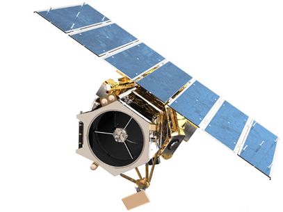
Launched from California, USA in September 2008, GeoEye-1 (formerly OrbView-5) is a high-resolution imaging satellite currently owned and operated by Maxar Technologies. Originally designed and built by commercial company GeoEye, the company was merged with DigitalGlobe, which has since been acquired by Maxar Technologies. GeoEye-1 imagery is used for various applications, including but not limited to air and marine transportation, defence, disaster response, oil and gas exploration, mining exploration and production, mapping of remote regions, insurance and risk management, location-based services and agricultural crop management.
Quick facts
Overview
| Mission type | EO |
| Agency | GeoEye, Maxar |
| Mission status | Operational (extended) |
| Launch date | 06 Sep 2008 |
| Measurement domain | Land |
| Measurement category | Multi-purpose imagery (land) |
| Measurement detailed | Land surface imagery |
| Instruments | GIS |
| Instrument type | High resolution optical imagers |
| CEOS EO Handbook | See GeoEye-1 (OrbView-5) summary |
Related Resources
Summary
Mission Capabilities
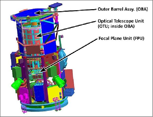
GeoEye-1 carries the GeoEye Imaging System (GIS), a pushbroom imaging system which has an optics subsystem (telescope assembly), a focal plane assembly (FPA) and a digital electronics subsystem.
The optics subsystem uses a Three Mirror Anastigmatic (TMA) telescope design with the primary mirror aperture having a diameter of 1.1 m. Three mirrors are used to image and focus the light, with two additional mirrors to direct the image to the FPA (Focal Plane Assembly). The telescope provides a near-perfect image to the FPA and converts the analog pixels into digitised signals.
Performance Specifications
GIS has a swath width of 15.2 km at nadir and offers 3 m geolocation accuracy, enabling customers to map natural and man-made features to within 3 m of their actual location. GeoEye-1 images at a resolution of 0.41 m for panchromatic data and 1.65 m for 4-band multispectral data. The Focal Plane Assembly (FPA) consists of an array of Charge Coupled Device (CCD) detectors with 8 µm pixel size for Panchromatic (PAN) and 32 µm pixel size for Multispectral (MS) imagery.
The satellite is in a sun-synchronous orbit, at an altitude of 681 km and an inclination of 98o. GeoEye-1 has the capability to revisit any point on Earth every 3 days. The Local Time on Descending Node (LTDN) is at 1030 hours and the period is 98 minutes.
Space and Hardware Components
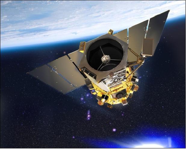
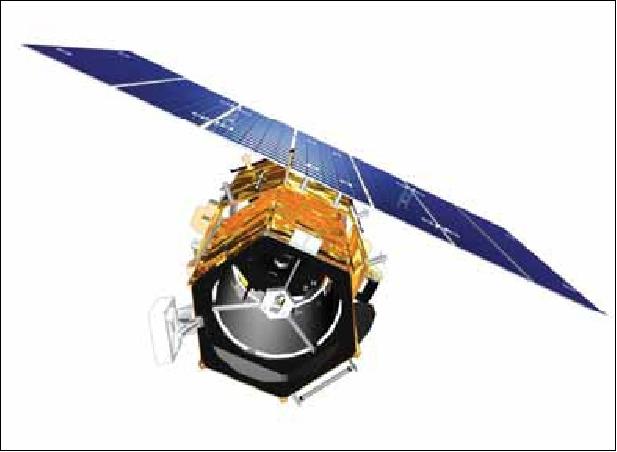
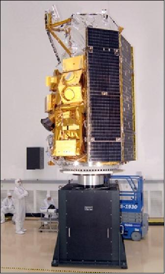
The GeoEye-1 satellite design is based on Spectrum Astro's (now General Dynamics/C4 Systems) SA-200 High Performance (SA-200HP) standard modular bus of Coriolis and SWIFT heritage. The spacecraft is 3-axis stabilised with a sophisticated attitude control system that provides a stable as well as an agile imaging platform. The satellite has outlasted its 10 years of expected operational life, being still operational as of July 2022.
The source data are stored on solid-state onboard recorders of 1.2 Tbit capacity. The downlink of imagery is in X-band at 740 or 150 Mbit/s, and the Telemetry, Tracking, and Command (TT&C) data are in S-band. Maxar has a fully integrated receiving, processing, and distribution network for delivering high-quality imagery products to customers around the world.
GeoEye-1 (OrbView-5)
Overview Spacecraft Launch Mission Status Sensor Complement Ground System References
GeoEye-1, formerly known as OrbView-5, is the next-generation high-resolution imaging mission of GeoEye, Dulles, VA, USA. In January 2006, the commercial imaging company GeoEye Inc. was formed, made up of former Orbimage of Dulles VA, and of former Space Imaging of Thornton, CO (Orbimage acquired Space Imaging in 2005 and gave the merged company the new name of GeoEye). The newly formed GeoEye company is the world's largest commercial satellite imagery provider.
On Sept. 30, 2004, OrbImage was awarded a NextView vendor contract of NGA (National Geospatial-Intelligence Agency). The contract, referred to as NextView OrbImage, provides long-term revenue commitments as well as capital for the development of OrbView-5. NGA's NextView program is designed to give US commercial imaging satellite operators the financing to build their satellites for high-resolution imaging.
GeoEye's principal partners for the development and launch of the GeoEye-1 satellite include General Dynamics (formerly Spectrum Astro), ITT Industries (imager), and Boeing Launch Services. GeoEye's partners for the ground segment include IBM and MDA (MacDonald, Dettwiler and Associates) of Richmond, BC, Canada. 1) 2)
As of January 31, 2013, GeoEye-1 is a satellite of the DigitalGlobe commercial constellation of Longmont, CO, USA (Ref. 10).
Spacecraft
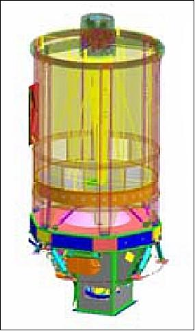
The GeoEye-1 spacecraft is being designed and developed at General Dynamics/C4 Systems of Gilbert, AZ (formerly Spectrum Astro) as prime contractor. The contract was award in Dec. 2004. The spacecraft design is based on the SA-200HP standard modular bus (of Coriolis and SWIFT heritage). The spacecraft is 3-axis stabilized with a sophisticated attitude control system to provide a highly stable, while also highly agile imaging platform.
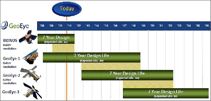
A body-pointing capability of up to ± 60º is being provided, made possible by enhanced reaction wheels (low jitter). The image geolocation accuracy is ≤ 3 m. The spacecraft mass is 1955 kg (bus mass = 1260 kg), the S/C design is fully redundant with an operational life of 7 years (the expected life is 10 years). 3) 4) 5) 6) 7)
Spacecraft dimensions | 4.35 m x 2.7 m (stowed configuration) |
Structure & Thermal | - An optical bench, attached to the spacecraft through kinematic mounts, provides precise thermally controlled alignment of the instruments |
C&DH (Command & Data Handling) subsystem | - Standard cPCI backplane/bus, RAD750 CPU, block redundant with automated handover to backup |
ADCS (Attitude Determination and Control Subsystem) | - 3-axis stabilized, (8) high-performance RWAs (Reaction Wheel Assemblies) |
Onboard propellant | 144.5 kg (adequate for a 15 year supply) |
Thrusters | 8, each of 22.2 N |
Spacecraft power | - Deployable, 7-panel solar array (GaAs), 3862 W EOL |
Launch mass | 1955 kg (bus mass of 1260 kg) |
Launch
GeoEye-1 was launched on Sept. 6, 2008 (18:50:57 UTC) on a Delta-2 (7420-10) vehicle from VAFB, CA. The launch provider was ULA (United Launch Alliance). 8)
Orbit: Sun-synchronous circular orbit, altitude = 681 km, inclination = 98º, period = 98 minutes, local equatorial crossing at 10:30 hours, effective revisit time capability ≤ 3 days.
Note: During late summer of 2013 the orbit altitude of the GeoEye-1 Satellite sensor was raised by Digital Globe from 681 km to 770 km. The GeoEye-1 new nadir GSD (Ground Sample Distance) is 46 cm for panchromatic data compared to the previous GSD of 41cm (Ref. 13). Despite this, GeoEye-1 imagery remains a valuable tool for high resolution requirements and is still being used for many applications today.
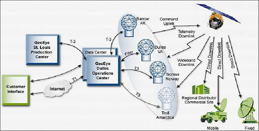
RF communications: The source data are being stored on solid-state onboard recorders of 1.2 Tbit capacity. The downlink of imagery in X-band at 740 Mbit/s (or at 150 Mbit/s), the TT&C data are in S-band. The S/C is being operated from the command and control facility at GeoEye headquarters in Dulles, VA, along with an imagery acquisition station. Three other acquisition stations will be operated or leased by GeoEye in Barrow, AK, Tromsø, Norway and Troll, Antarctica (the TrollSat station is located at 72º S and 2º E). The latter two stations are being leased from KSAT (Kongsberg Satellite Services) of Tromsø, Norway.
A total of four stations are needed to handle primary data reception due to the large volume of data that will be captured by the satellite. In addition, GeoEye will continue to support a network of receiving stations owned and operated by local business partners, referred to as Regional Affiliates and Regional Distributors.
Ground segment: GeoEye has built a fully integrated receiving, processing, and distribution network for delivering high-quality imagery products to customers around the world.
In late 2006, GeoEye purchased high-bandwidth, high-performance computer technology from SGI (Silicon Graphics Inc.). Four SGI Altix systems were installed at the Dulles (VA) ground station for data processing, distribution, and archiving services.
Mission Status
• According to the WMO website, GeoEye-1 of DigitalGlobe is operational in 2016. 9)
• The GeoEye-1 spacecraft of DigitalGlobe and its payload are operating nominally in 2015.
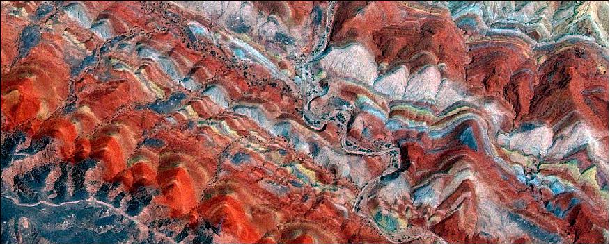
Legend to Figure 7: The Rainbow Mountains, a new UNESCO World Heritage Site, are located at the Zhangye Danxia Landform Geological Park in the Gansu Province of northwestern China. Zhangye 's Danxia was formed by the erosion of red sandstone, forming isolated peaks and steep stratified outcrops. Its special geological structure, combined with long-term desert conditions , freeze-thaw peeling, and wind and water erosion gave rise to its present appearance. Geologists believe that Danxia topography was formed by folding of layered oceanic crust. Exposed slanting rock layers have different colors, textures, shapes, sizes, and patterns. The combination of differences in density and erosion create towering peaks, cave holes, and stone halls.
• In 2014, the GeoEye-1 spacecraft of DigitalGlobe and its payload are operating nominally completing 6 years on orbit in Sept. 2014.
• In 2013, the GeoEye-1 spacecraft and its payload are operating "nominally".
Merger of DigitalGlobe and GeoEye 10) 11) 12)
• On January 31, 2013, DigitalGlobe and GeoEye have completed their merger, creating a global leader in Earth imagery and geospatial analysis. Hence, the GeoEye-1 satellite is now being operated by DigitalGlobe. 10) 11)
- The merger was forced by the government's decision to reduce funding for commercial satellite imagery purchases in light of budget constraints and reduced demand for this type of satellite imagery. 12)
- Though referred to as commercial companies, both GeoEye and DigitalGlobe have been heavily dependent on the government as a market for their high resolution satellite imagery. A series of contracts over the past decade under the auspices of the National Geospatial-Intelligence Agency (NGA), part of the Intelligence Community, assured the companies of sufficient revenue to build new satellites and remain solvent as they sought to develop non-government markets.
- Last year, however, NGA informed GeoEye that it would not continue supporting the company under the most recent contract, EnhancedView, signed in 2010. The Senate Armed Services Committee attempted to come to GeoEye's rescue, but by the time the FY2013 National Defense Authorization Act reached the final stages of negotiation in late December, the die was cast.
- From a space policy perspective the government's decision to discontinue its arrangement with GeoEye is an opportunity to extract lessons learned about public-private partnerships in commercial space. The growing number of companies looking to the government to help fund their space systems and serve as a market for their wares also might be well served to recalibrate expectations. Policies are good, but they are often trumped by budgets.
• During late summer of 2013 the orbit altitude of the GeoEye-1 Satellite sensor was raised from 681 km to 770 km. GeoEye-1 new nadir GSD (Ground Sample Distance) is 46 cm compared to the previous GSD of 41cm. 13)
• In 2012, the GeoEye-1 spacecraft and its payload are operating "nominally". The satellite imagery is used for a variety of purposes, including but not limited to defense, disaster response, air and marine transportation, oil and gas exploration, mining production and exploration, mapping of remote regions, location-based services, insurance and risk management, agricultural crop management, etc.
Several geolocation accuracy studies of the imagery were performed. 14) 15)
Period | Mono | Stereo | ||||||
| # images | CE90 (m) | RMSE (m) | # pairs | CE90 (m) | RMSE (m) | LE90 (m) | RMSE (m) |
2009 Q2-Q4 | 530 | 3.6 | 2.3 | 222 | 3.4 | 2.2 | 3.2 | 2.0 |
2010 | 136 | 3.8 | 2.4 | 65 | 3.5 | 2.2 | 3.5 | 2.3 |
2011 | 193 | 2.8 | 1.9 | 43 | 2.8 | 1.9 | 2.9 | 2.8 |
Legend to Table 2:
- RMSE (Root Mean Square Error)
- CE90 (Circular Error of 90%)
- LE90 (Linear Error of 90%)
• GeoEye maintains continuous calibration assessments for the GIS (GeoEye Imaging System) instrument of GeoEye-1 involving the geometric, radiometric and focus parameters to verify the performance quality of the imagery. 16)

Legend to Figure 8: This half-meter resolution satellite image shows the Pearl Harbor Memorial, located about two miles west of the Honolulu Airport in Pearl Harbor on the island of Oahu, Hawaii. GeoEye tasked its GeoEye-1 satellite on Dec. 7, 2011 to commemorate the 70th anniversary of the Pearl Harbor Attack on Dec. 7, 1941. The image specifically shows the USS Missouri (center), a museum ship docked at Battleship Row, and crowds of people standing in formation on the dock. The USS Arizona Memorial (upper right) was built over the remains of the sunken battleship USS Arizona, which can be seen below the white memorial under the water's surface. The Arizona Memorial is managed by the National Park Service and is now a part of the dedicated WWII Valor in the Pacific National Monument Ref. 17).
• In October 2011, an ELR (Enhanced Line Rate) firmware package was uploaded with the objective to increase the overall collection capacity v. the SLR (Standard Line Rate) of the GIS camera. The ELR features are: 18)
- ELR camera slew rate is double that of SLR
- Faster collection of large area targets (25% – 30% increase)
- Point target collection times largely unchanged
- Camera on times decrease up to 40%
- End-to-end capacity increase: 15% – 20%.
• The GeoEye-1 spacecraft and its payload are operating "nominally" (with a downlink antenna pointing anomaly) in 2011. GeoEye-1 continues to have excellent radiometric performance.
- The geolocation accuracy performance assessment for GeoEye-1 system during 2010 was better than 4 m for mono CE90 and stereo CE90/LE90 (Circular Error of 90%/Linear Error of 90%). The GeoEye-1 system continues produce very good geolocation accuracy performance. 19)
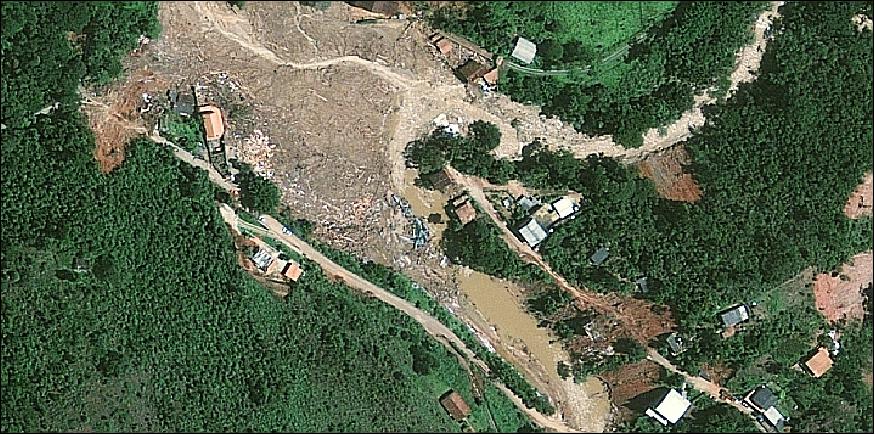
Legend to Figure 10: This half-meter resolution satellite image shows numerous landslides in Nova Friburgo, which is located north of Rio de Janeiro, Brazil. According to news reports the slides were triggered by deluges in the mountains just north of Rio and are the deadliest natural disaster to hit Brazil since flooding occurred four decades ago. The image was collected by the GeoEye-1 satellite on January 20, 2011 from 681 km in space as it moved from north to south over Brazil. 20)
• The GeoEye-1 spacecraft and its payload are operating "nominally" (with a downlink antenna pointing anomaly) in 2010.
• In mid-December 2009, GeoEye Inc. reported that the GeoEye-1 satellite has developed a glitch in its antenna-pointing system that could affect the operations of the company's overseas partners but will not diminish GeoEye's ability to serve its biggest customer, the U.S. NGA (National Geospatial-Intelligence Agency). 21)
The defect reduces GeoEye-1's ability to take images and simultaneously downlink to ground stations other than the four stations operated by GeoEye itself. For the GeoEye-owned facilities, GeoEye-1's imaging and downlinking functions are not performed simultaneously. 22)
• In early Dec. 2009, GeoEye announced the start of GeoEye-1 commercial operations for its regional affiliate in Saudi Arabia, KACST (King Abdulaziz City for Science and Technology). In addition to directly acquiring GeoEye-1 imagery, KACST will be able to provide other GeoEye-1 imagery and value-added products to its customers. 23)
• However, on May 12, 2009, the GeoEye company disclosed a problem with the GIS camera of GeoEye-1 which leaves small areas of black and white in certain color images collected. The investigation team determined, that the issue is only present in one profile but not in the others. The issue doesn't affect resolution or accuracy. There is little or no impact for GeoEye's Service Level Agreement with NGA. The causes of the problem are still being investigated. 24)
• In February 2009, GeoEye announced the start of commercial operations for its GeoEye-1 spacecraft. On Feb. 22, 2009, the National Geospatial-Intelligence Agency (NGA) notified the Company that imagery from the GeoEye-1 satellite has been certified as meeting their stringent requirements for quality, accuracy and resolution. As a result of the certification, the GeoEye-1 satellite is fully commissioned. The NextView program is designed to ensure that the NGA has access to commercial imagery in support of its mission to provide timely, relevant and accurate geospatial intelligence in support of national security. 25) 26)
• As of Dec. 2008, GeoEye-1 still experienced geolocation problems that prevented the company of selling its imagery.
• On Nov. 11, 2008 GeoEye Inc. reported that the GeoEye-1 spacecraft will not enter commercial service until December due to software glitches on the ADCS (Attitude Determination and Control Subsystem) that went undetected in ground testing. 27)
• On Oct. 8, 2008 GeoEye Inc. released the first, color half-meter ground resolution image taken from its GeoEye-1 satellite (Figure 14). The spacecraft had been undergoing calibration and check-out since it was launched on Sept. 6 from Vandenberg Air Force Base in California. 28)
Sensor Complement
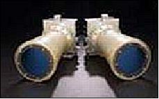
The requirements of GeoEye-1 called for panchromatic imagery with a resolution of 0.41 m and multispectral imagery with a resolution of 1.64 m. The imager has been designed and developed by ITT Space Systems Division, formerly Kodak Remote Sensing Systems of Rochester, New York, which built also the sensor for Ikonos-2 (launch April 27, 1999). In January 2007, the GeoEye-1 imager system was delivered to General Dynamics for integration into the spacecraft. 29) 30)
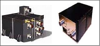
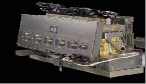
GIS (GeoEye Imaging System)
GIS is a pushbroom imaging system whose basic elements are the optics subsystem (telescope assembly), the focal plane assembly (CCD detector), and the digital electronics subsystem. The optics subsystem employs a TMA (Three Mirror Anastigmatic) telescope design with a primary mirror aperture of 1.1 m in diameter. Three mirrors are used to image and focus the light, and two additional mirrors to direct the image to the FPA (Focal Plane Assembly). The telescope is designed to give a near-perfect (diffraction limited) image to the FPA and to convert the analog pixels into digitized signals.
The FPA consists of an array of CCD detectors with 8 µm pixel size for PAN and 32 µm pixel size for multispectral imagery. ITT has included an outer barrel and door assembly to help protect the telescope and maintain its thermal environment.
Imager type | Pushbroom imager. Lline scan imaging system with TDI (Time Delay Integration) capability | |
Imaging mode | Panchromatic (Pan) | Multispectral (MS) |
Spectral range | 450-900 nm | 450-510 nm (blue) |
Spatial resolution at nadir | 0.41 m GSD | 1.64 m GSD |
Swath width | 15.2 km (multiple adjoining paths can be imaged in a target area in a single orbit pass due to S/C agility) | |
Detectors | Pan: Si CCD array (8 µm pixel size) with a row of > 35,000 detectors | |
Data quantization | 11 bit | |
Geolocation accuracy of imagery | ≤ 3 m (using a GPS receiver, a gyroscope and a star tracker) without any GCP (Ground Control Points) | |
Optics | TMA telescope (5-element modified Cassegrain optical design) | |
FOV (Field of View) | > 1.28º | |
Instrument size | 3 m tall (the volume is 5.3 m3) | |
Total instrument mass | 452 kg | |
In orbit, the GIS instrument is providing the highest spatial resolution available in 2008 [GSD (Ground Sample Distance) = 41 cm for Pan and 1.64 m for MS]. The operational support modes of the GIS instrument are: 31)
• Simultaneous panchromatic and multispectral (pan-sharpened) 32)
• Panchromatic only
• Multispectral only
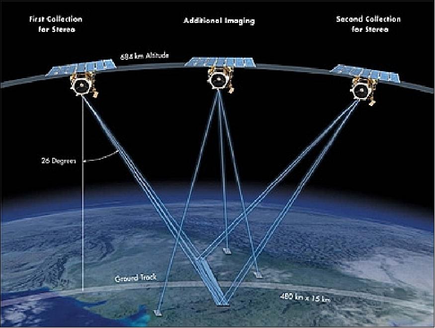
The agile spacecraft is capable to provide also stereo observations in any direction (along-track or cross-track with a continuous stereo area up to 6270 km2 daily). The daily monoscopic collection capacity is:
- Up to 700,000 km2 of panchromatic imagery
- Up to 350,000 km2 of pan-sharpened multispectral imagery
As a major customer, NGA will receive priority tasking and a large discount for agreeing to purchase a large volume of imagery. But there will still be a large amount of capacity dedicated to commercial customers and for the company to build a vast archive of imagery in a relatively short period of time.
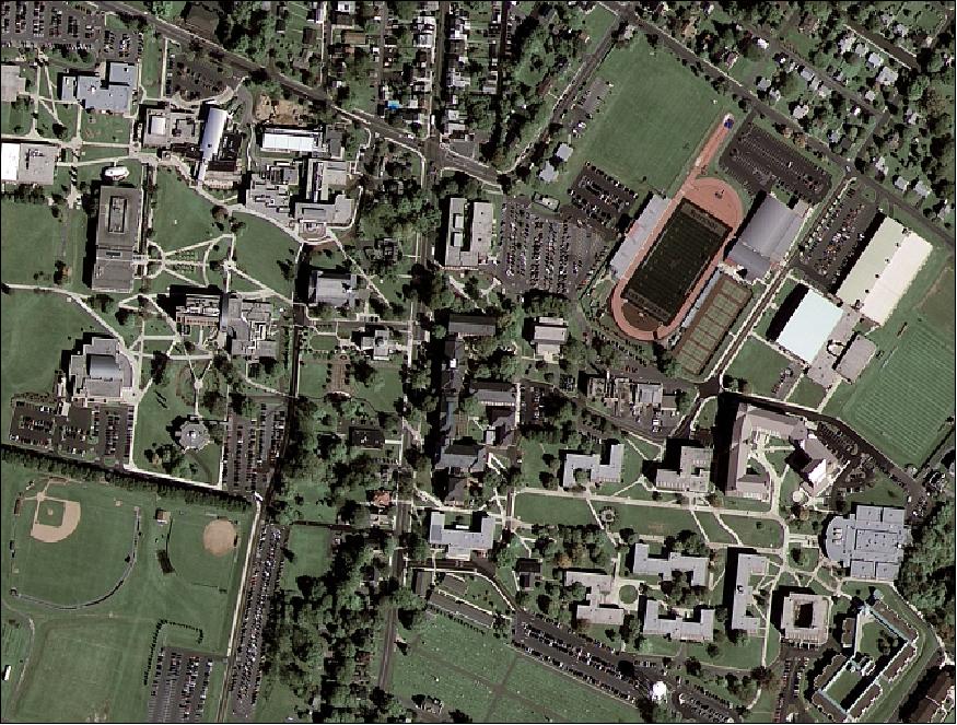
The color image of Figure 14 was observed on October 7, 2008 from an orbital altitude of 761 km as GeoEye-1 moved down the eastern seaboard of the United States. Although the satellite collects Pan imagery at 0.41m ground resolution, due to U.S. licensing restrictions, commercial customers will only get access to imagery that has been processed to 0.5 m ground resolution.
Ground Segment
MDA (MacDonald, Dettwiler and Associates) and Orbit Logic have upgraded elements of GeoEye's ground segment. The receiving antennae are located at the Company's headquarters in Dulles, VA and in Barrow, AK. Kongsberg Satellite Services is providing leased ground terminal services in Tromso, Norway and Troll, Antarctica.
References
1) K. P. Corbley, "GeoEye-1 Satellite Coming," GEOconnexion International Magazine, Sept. 2006, pp. 50-55, http://www.geoconnexion.com/uploads/geoeye_intv5i8.pdf
2) Dennis Jones, "GeoEye Corporate Overview," JACIE (Joint Agency Commercial Imagery Evaluation) Workshop, Fairfax, VA, USA, March 14-16, 2006, URL: http://calval.cr.usgs.gov/JACIE_files/JACIE06/Files/18Jones.pdf
3) J. Croft, "GeoEye's Next-Generation Imaging Satellite," GeoInformatics, June 2008, pp. 18-21, URL: [web source no longer available]
4) http://launch.geoeye.com/LaunchSite/about/partners.aspx
5) "GeoEye-1 Fact Sheet," URL: http://launch.geoeye.com/LaunchSite/assets/documents/geoeye1_factsheet.pdf
6) http://www.aerospace-technology.com/projects/geoeye-1-satellite/
7) "Data sheet GeoEye-1," DigitalGlobe, URL: https://dg-cms-uploads-production.s3.amazonaws.com/uploads/document/file/97/DG_GeoEye1.pdf
8) "GeoEye-1 Satellite Launches Into Space From Vandenberg Air Force Base, California," GeoEye, Sept. 6, 2008, URL: http://geoeye.mediaroom.com/index.php?s=43&item=304
9) "Satellite: GeoEye-1," WMO/OSCAR, Jan. 14, 2016, URL: http://www.wmo-sat.info/oscar/satellites/view/494
10) "DigitalGlobe and GeoEye Complete Combination," DigitalGlobe, Press Release, Jan. 31, 2013, URL: [web source no longer avaliable]
11) "DigitalGlobe and GeoEye Complete Combination," Space Daily, Feb. 6, 2013, URL: http://www.spacedaily.com/reports/DigitalGlobe_and_GeoEye_Complete_Combination_999.html
12) Marcia S. Smith, "DigitalGlobe and GeoEye Complete Merger," Space Policy Online.com, Jan. 31, 2013, URL: http://www.spacepolicyonline.com/news/digitalglobe-and-geoeye-complete-merger
13) "GeoEye-1 Satellite Sensor (0.46m)," Satellite Imaging orp., URL: http://www.satimagingcorp.com/satellite-sensors/geoeye-1/
14) David Mulawa, "GeoEye Geolocation Assessment and Reporting Update for 2011," Proceedings of the 11th Annual JACIE (Joint Agency Commercial Imagery Evaluation ) Workshop, Fairfax, VA, USA, April 17-19, 2012, URL: http://calval.cr.usgs.gov/wordpress/wp-content/uploads/mulawa-GeoEye-geolocation-JACIE-2012.pdf
15) Paul C. Bresnahan, "Geolocation Accuracy Re-Evaluations of GeoEye-1 and QuickBird-2," Proceedings of the 11th Annual JACIE (Joint Agency Commercial Imagery Evaluation ) Workshop, Fairfax, VA, USA, April 17-19, 2012, URL: http://calval.cr.usgs.gov/wordpress/wp-content/uploads/Bresnahan_Paul_JACIE2012_NIQU_CCAP_Geolocation_Accuracy
_GE1_QB2_Approved-for-Public-Release-12-182.pdf
16) Nancy E. Podger, "Overview of Image Quality Performance of the GeoEye-1 High Resolution Imaging Satellite," Proceedings of the 11th Annual JACIE (Joint Agency Commercial Imagery Evaluation ) Workshop, Fairfax, VA, USA, April 17-19, 2012, URL: http://calval.cr.usgs.gov/wordpress/wp-content/uploads/Podger_2012_JACIE_GeoEye-1_Image_Quality.pdf
17) "Pearl Harbor Memorial, 70th Anniversary - Pearl Harbor, Honolulu, Hawaii USA," GeoEye, URL: http://www.geoeye.com/CorpSite/gallery/gallery-image.aspx?2092&g=18
18) Preston Mattox, "GeoEye-1 New Sensor Mode – 1x2 Multispectral Pixel Aggregation," Proceedings of the 11th Annual JACIE (Joint Agency Commercial Imagery Evaluation ) Workshop, Fairfax, VA, USA, April 17-19, 2012, URL: http://calval.cr.usgs.gov/wordpress/wp-content/uploads/Mattox_JACIE_2012_GeoEye-1_New-Sensor-Mode_1x2_Multispectral_Pixel_Aggregation.pdf
19) David Mulawa, "GeoEye-1 Geolocation Assessment and Reporting Update," 10th Annual JACIE ( Joint Agency Commercial Imagery Evaluation) Workshop, March 29-31, 2011, Boulder CO, USA, URL: http://calval.cr.usgs.gov/JACIE_files/JACIE11/Presentations/WedPM/210_mulawa_JACIE_11.095.pdf
20) "GeoEye Featured Satellite Images," URL: http://www.geoeye.com/CorpSite/gallery/detail.aspx?iid=357&gid=1
21) Peter B. de Selding, "Glitch Suspends GeoEye-1 Operations," Space News Dec. 17, 2009, URL: http://www.spacenews.com/earth_observation/091217-glitch-temporarily-suspends-geoeye-1-operations.html
22) Peter B. de Selding, "GeoEye Revenue Up Despite Satellite Antenna Issue," Space News, May 17, 2010, p. 10, URL: http://www.spacenews.com/earth_observation/100512-geoeye-sales-rise.html
23) "GeoEye Announces the Start of GeoEye-1 Commercial Operations for its Regional Affiliate in Saudi Arabia," Dec. 8, 2009, URL: http://geoeye.mediaroom.com/index.php?s=43&item=345
24) Turner Brinton, "GeoEye: Camera Glitch on New Satellite Won't Affect NGA Sales," Space News, May 18, 2009, p. 6
25) "GeoEye-1 Satellite Attains Full Operational Capability Certification," Space Mart Feb. 23, 2009, URL: http://www.spacemart.com/reports/GeoEye_1_Satellite_Attains_Full_Operational_Capability
_Certification_999.html
26) "GeoEye-1 Satellite Attains Full Operational Capability Certification from the National Geospatial-Intelligence Agency," GeoEye, Feb. 20, 2009, URL: http://geoeye.mediaroom.com/index.php?s=43&item=317
27) Peter B. de Selding, "Start of GeoEye-1 Service Delayed by Software Glitch," Space News Nov. 17, 2008, p. 6
28) "GeoEye Releases First Image Collected by Its New GeoEye-1 Earth-Imaging Satellite," GeoEye, Oct. 8, 2008, URL: http://geoeye.mediaroom.com/index.php?s=43&item=308
29) J. Croft, "GeoEye & ITT Team Up for Out-of-this-World Technology," Imaging Notes Magazine, Spring 2008, Vol. 23, No 1, URL: http://www.imagingnotes.com/go/article_free.php?mp_id=128&cat_id=21
30) "ITT's Integrated Electro-Optical Payload for GeoEye's Next-Generation Earth-Imaging Satellite—GeoEye-1," ITT, URL: http://launch.geoeye.com/LaunchSite/assets/documents/ITT_Fact_Sheet2.pdf
31) GeoEye-1 the world's highest resolution commercial satellite," Eurimage, URL: http://www.eurimage.com/products/pdf/e-GEOS%20GeoEye.pdf
32) C. S. Fraser , M. Ravanbakhsh, "Georeferencing from GeoEye-1 imagery: early indications of metric performance," Proceedings of the ISPRS 2009 Workshop, 'High-Resolution Earth Imaging for Geospatial Information,' Hannover, Germany, June 2-5, 2009, URL: http://www.isprs.org/proceedings/XXXVIII-1-4-7_W5/paper/Fraser-207.pdf
33) William Schuster, "GeoEye CorporateOverview - For the JACIE Civil Commercial Imagery Evaluation Workshop," March 20-22, 2007, Fairfax, VA, USA, URL: http://calval.cr.usgs.gov/JACIE_files/JACIE07/Files/110Schus.pdf
34) Martin H. Taylor, Gene Dial, "GeoEye's Imagery Collection and Production Services Current Performance and Future Systems," 10th Annual JACIE ( Joint Agency Commercial Imagery Evaluation) Workshop, March 29-31, 2011, Boulder CO, USA, URL: http://calval.cr.usgs.gov/JACIE_files/JACIE11/Posters/11.140_Taylor_JACIE2011_Poster.pdf
35) Preston Mattox, "Introducing the GeoEye Sensor Performance Lab," 10th Annual JACIE ( Joint Agency Commercial Imagery Evaluation) Workshop, March 29-31, 2011, Boulder CO, USA, URL: http://calval.cr.usgs.gov/JACIE_files/JACIE11/Presentations/WedPM/145_Mattox_JACIE_11.035.pdf
The information compiled and edited in this article was provided by Herbert J. Kramer from his documentation of: "Observation of the Earth and Its Environment: Survey of Missions and Sensors" (Springer Verlag) as well as many other sources after the publication of the 4th edition in 2002. - Comments and corrections to this article are always welcome for further updates (eoportal@symbios.space).
Overview Spacecraft Launch Mission Status Sensor Complement Ground System References