GOES (Geostationary Operational Environmental Satellite) 2nd Generation
EO
Atmosphere
Ocean
Cloud type, amount and cloud top temperature
Geostationary Operational Environmental Satellite (GOES) 2nd Generation Series consisted of a group of five satellites, sequentially named GOES-I, J, K, L and M and designated numbers 8 - 12 in place of consecutive letters after launch. The satellites were operated by the National Oceanic and Atmospheric Administration (NOAA) and the National Aeronautics and Space Administration (NASA) and provided geostationary weather monitoring. All five satellites were launched between 1994 and 2001, with a design lifetime of 7 years.
Quick facts
Overview
| Mission type | EO |
| Agency | NOAA |
| Mission status | Mission complete |
| Launch date | 17 May 1974 |
| End of life date | 19 Aug 2013 |
| Measurement domain | Atmosphere, Ocean, Land |
| Measurement category | Cloud type, amount and cloud top temperature, Liquid water and precipitation rate, Atmospheric Temperature Fields, Aerosols, Multi-purpose imagery (ocean), Radiation budget, Multi-purpose imagery (land), Surface temperature (land), Surface temperature (ocean), Atmospheric Humidity Fields, Ozone, Atmospheric Winds |
| Measurement detailed | Cloud top height, Ocean imagery and water leaving spectral radiance, Aerosol absorption optical depth (column/profile), Cloud cover, Precipitation intensity at the surface (liquid or solid), Cloud imagery, Aerosol Extinction / Backscatter (column/profile), Upward long-wave irradiance at TOA, Aerosol effective radius (column/profile), Fire temperature, Fire fractional cover, Atmospheric specific humidity (column/profile), O3 Mole Fraction, Atmospheric temperature (column/profile), Land surface temperature, Sea surface temperature, Cloud top temperature, Wind profile (horizontal), Atmospheric stability index |
| Instruments | LRIT, SEM (GOES), S&R (GOES), SXI, Imager, GOES Comms, Sounder, VISSR, SEM/EPS, WEFAX, SEM (POES), SEM/MAG, SEM/XRS-EUV, DCS (NOAA), SEM/HEPAD, VAS, DCIS |
| Instrument type | Imaging multi-spectral radiometers (vis/IR), Space environment, Other, Communications, Data collection, Atmospheric temperature and humidity sounders, In situ |
| CEOS EO Handbook | See GOES (Geostationary Operational Environmental Satellite) 2nd Generation summary |
Summary
Mission Capabilities
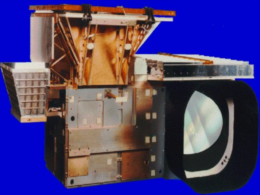
The instruments on board the GOES 2nd Generation spacecraft included the GOES Imager, GOES Sounder, Space Environment Monitor (SEM), Search and Rescue Satellite (S&RSAT), and a Data Collection System (DCS). The GOES Imager was a multispectral five-channel instrument that imaged the Earth’s surface to analyse various weather-related phenomena for storm monitoring and prediction. The GOES Sounder is a 19-channel radiometer used to sense emitted thermal energy and reflected solar energy to calculate vertical profiles of temperature and moisture. SEM was a package that consisted of an Energy Particle Sensor (EPS), High Energy Proton and Alpha Particle Detector (HEPAD), magnetometer, Solar X-Ray Sensor (XRS) and Solar X-Ray Imager (SXI). This package measured solar radiation in the X-ray and Extreme Ultraviolet (EUV) regions, as well as the magnetic field and energetic particle environment during orbit. SXI monitored the sun’s X-rays to detect solar flares at an early stage to ensure human and space mission safety. S&RSAT was used to detect emitted distress signals on Earth.
Performance Specifications
The GOES Imager utilised a Cassegrain telescope to image in one visible spectrum (VIS) band, two midwave infrared (MWIR) bands and two thermal infrared (TIR) bands, with a spatial resolution of 4 km x 4 km on MWIR and TIR bands. The resolution in the VIS band was 1 km x 1 km. The GOES Sounder also utilised a Cassegrain telescope which imaged in nine TIR bands, six MWIR bands, three shortwave infrared (SWIR) bands, and one VIS band. SEM measured two solar X-ray flux (XRS) bands and five EUV bands, and detected protons in seven bands, alpha particles in six bands, and electrons in three bands.
The satellites operated in a geostationary orbit at an altitude of 35,786 km above the equator.
Space and Hardware Components
The second generation GOES spacecraft were all constructed by Space Systems/Loral (SS/L) and the sensors were provided by ITT (International Telegraph and Telephone) Aerospace. Furthermore, the spacecraft was designed to be modular, with a propulsion module, electronics module, solar array, solar sail and sensor complement. The propulsion module was crucial in adjusting the orbit of the satellite from on-orbit standby to the required orbit.
GOES (Geostationary Operational Environmental Satellite) 2nd Generation Series
Spacecraft Operational Status Sensor Complement Ground Segment References
GOES is a joint NOAA/NASA weather satellite series. NOAA is responsible for providing funding, requirements, and operation of the system in orbit. NASA, under contract from NOAA, is responsible for spacecraft procurement, design, and development of the spacecraft and its instruments, and the launch of each satellite. NOAA owns and operates the satellites and provides the services to the user community.
Background
ATS-1 (Applications Technology Satellite) was the first US geostationary satellite (launched December 6, 1966) with the ability to “see weather systems” by imaging the full-disk Earth every half hour with a spin scan camera. Operational use of ATS-3 (launched November 6, 1967) imagery at NSSFC (National Severe Storm Forecast Center) and at NHC (National Hurricane Center) followed in 1972. A total of six spacecraft were part of the ATS series. The prime objective of the series was to test new technologies (spin stabilization, gravity gradient stabilization, demonstration of data collection from remote terminals, etc.) for communications and to investigate the geostationary orbit environment.
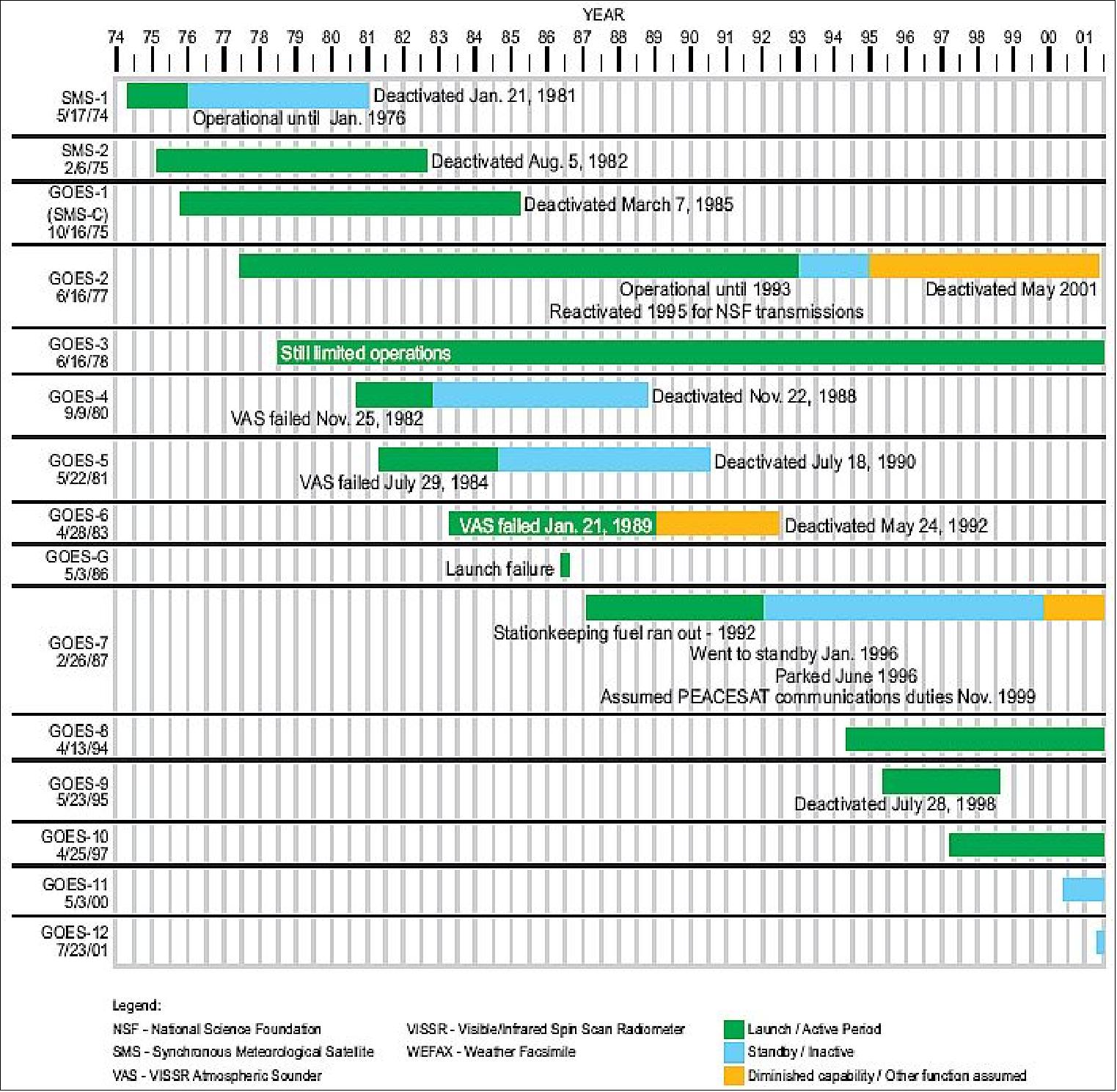
NASA developed two Synchronous Meteorological Satellites (SMS-1, -2), which were launched on May 17, 1974 and February 6, 1975. A total of eight additional “GOES” satellites in the same series were funded by NOAA, the first being GOES-1 launched on October 16, 1975. The last satellite in this initial series (1st generation) was GOES-7. 1) 2) 3) 4)
Spacecraft | Launch | Comment | S/C Generation |
ATS | Dec. 6, 1966, May 30, 1974 | ATS (Applications Technology Satellite) was a series of six NASA satellites (multi-purpose engineering spacecraft in GEO) with the objective to explore and flight-test new technologies and techniques for communications, meteorological and navigation satellites. | Demonstration S/C in GEO |
SMS-1 | May 17, 1974 | SMS-1 (Synchronous Meteorological Satellite-1) is the first operational geostationary weather satellite, located at 45º W. S/C mass = 627 kg, full-disk images of western hemisphere every 30 min. SMS-1 was deactivated by NASA on January 21, 1981 |
|
SMS-2 | Feb. 6, 1975 | After the successful launch of the SMS satellites, NASA turned over the geostationary satellite program to NOAA for operation. |
|
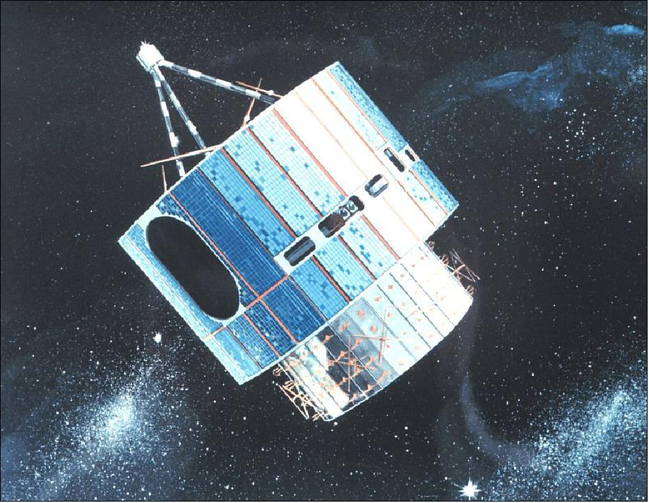
GOES-1 | Oct. 16, 1975 | S/C mass of 293 kg. GOES-1 to -7 were spin-stabilized spacecraft with a design life of 5 years. The main instrument was VISSR (Visible Infrared Spin Scan Radiometer) built by HUghes SBRC. GOES-1 was deactivated by NASA on March 7, 1985 | 1st Generation GOES S/C |
GOES-2 | Jun. 16, 1977 | GOES-2 was operational until 1993. It was re-activated in 1995 to broadcast NSF transmissions from the South Pole to public broadcasting facilities in the U.S. In May 2001, GOES-2 was boosted into a higher orbit to make room for other GEO S/C | |
GOES-3 | Jun. 16, 1978 | Ops period: 1978-1993. Re-activated in 1995 to transmit educational programming throughout the Hawaiian Islands from the University of Hawaii. | |
GOES-4 | Sept. 9, 1980 | GOES-4 VAS failed in Nov. 1982. The VAS instrument of GOES-4 was able to provide the first vertical temp. and moisture measurements from GEO. GOES-4 was de-activated on Nov. 22, 1988 | |
GOES-5 | May 22, 1981 | GOES-D to -H spacecraft were built by Boeing. | |
GOES-6 | Apr. 28, 1983 | GOES-6 is out of service due to equipment failure in 1989. Orbit is unstable. | |
GOES-G | May 3, 1986 | Launch failure | |
GOES-7 | Feb. 26,1987 | - On April 12, 2012, GOES-7 was “retired” from service with a final burn into a graveyard orbit (300 km above its GEO orbit, Ref. 5) | |
GOES-8 | Apr. 13, 1994 | First second generation S/C (3-axis stabilized); S&RSAT became operational on GOES-8; GOES-8 operated for over 6.5 years (design life of 3 years). GOES-8 was functioning at 75º W. The S/C was deactivated on May 5, 2004 and boosted into a higher orbit (350 km above GEO) | 2 nd Generation S/C |
GOES-9 | May 23, 1995 | GOES-I to -M S/C were built by SS/L; In July 2002, GOES-9 was removed from operational service in 1998 - to act as backup for GMS-5 of Japan, starting in 2003 | |
GOES-10 | April 25, 1997 | In the initial mission, the S/C suffered a solar array malfunction. A recovery procedure was performed to invert the S/C and operate the solar array in the reverse direction. The S/C became operational in July 1998. It replaces GOES-9 which had problems with its attitude control system. GOES-10 is positioned at 135º W. The design life of KLM S/C is 5 years. | |
GOES-11 | May 3, 2000 | - GOES-11 was launched into a storage orbit at 105º W (backup) | |
GOES-12 | July 23, 2001 | GOES-12 is the last of the 2nd generation S/C built by SS/L | |
GOES-13 | May 24, 2006 | GOES-N, and -O (options for -P and -Q) S/C are being built by BSS (Boeing Satellite Systems) on a Boeing 601 S/C platform, the S/C feature a star tracker for pointing | 2 nd Generation S/C extended |
GOES-14 | June 27, 2009 | GOES-14 is located at 105º W (on-orbit storage) | |
GOES-15 | March 4, 2010 | GOES-15 is located at 135º W | |
GOES-Q |
| NOAA may not exercise the option for GOES-Q | |
GOES-R | Nov. 19, 2016 | Start of 3rd generation satellites and instruments (ABI, ABS) | 3 rd |
The GOES program is a key element in US National Weather Service (NWS) operations. GOES weather imagery and quantitative sounding data represent a continuous and reliable stream of environmental information used to support weather forecasting, severe storm tracking, and meteorological research. NOAA policy calls for the operation of two meteorological satellites in geostationary orbit. Each of these spacecraft views almost a third of the Earth's surface: one monitors North and South America and most of the Atlantic Ocean, the other North America and the Pacific Ocean basin. GOES-East is nominally positioned at 75º W longitude over the equator, while GOES-West is nominally positioned at 135º W longitude over the equator plane. The two spacecraft operate together to produce a full-face picture of the Earth, day and night. Coverage extends approximately from 20º W longitude to 165º E longitude. The GOES mission consists of the space segment and the ground segment.
In general, meteorological observations from GEO offer repetitive synoptic views of large Earth regions (about 40% of the Earth's surface are viewed by one satellite); they are ideal to monitor large-scale phenomena in various fields such as in meteorology, hydrology and oceanography. Satellites in GEO feature a fixed-position, constant-signal and continuous-coverage relationship between the spacecraft and its ground segment (seemingly hovering at a particular longitude over the equator at an altitude of about 35,800 km). Hence, they provide a constant monitoring capability for observing any type of quickly developing weather phenomena (severe weather conditions such as tornadoes, flash floods, hail storms, hurricanes, etc.) or diurnal variations in weather events. Due to their position above the equator, GEO satellites provide only a distorted view of the polar regions where they are of practically no use. With the exception of these high latitude regions, the existing system of geostationary meteorological satellites give a global view of our planet. - GEO satellite observations have also important roles in the development of a climate observing system.
In addition, GEO observations are used to estimate rainfall during thunderstorms and hurricanes for flash flood warnings, as well as estimates of snowfall accumulations and the overall extent of snow cover.
Most GEO meteorology spacecraft feature, apart from their meteorological payload, also data collection systems for environmental monitoring as well as S&R (Search and Rescue) systems in support of humanitarian rescue operations. Some agencies (ISRO) add the meteorological use of the GEO satellite to the prime function of telecommunication support. ESA is also using its Meteosat series for telecommunication purposes, namely the distribution of meteorological data to the world-wide user community.
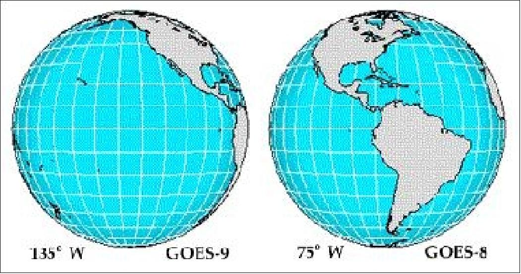
Coverage: GOES-East (slot at 75º W) provides the primary coverage of real-time weather information for North and South America and most of the Atlantic Ocean. The GOES-West (slot at 135º W) coverage region is mostly over the Pacific Ocean and North America. Total coverage of the system extends approximately from 20º W longitude to 165º E longitude. The main mission is carried out by the primary instruments, the Imager and the Sounder.
Spacecraft
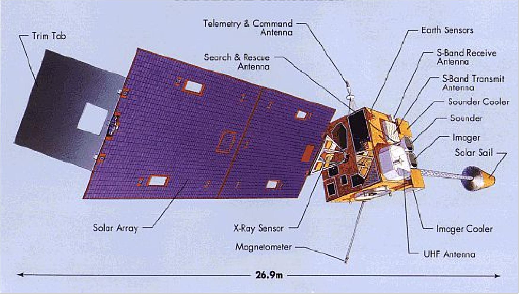
All GOES spacecraft (starting from GOES-I) are of three-axis, body-stabilized design capable of continuously pointing the optical line of sight of the imaging and sounding radiometers to the Earth. GOES S/C (I to M) were built and integrated by Space Systems/Loral (SS/L) for NASA/GSFC; the sensors (imager and sounder) are provided by ITT Aerospace of Fort Wayne, IND. NOAA is the owner and operator of all GOES S/C. 7) 8) 9) 10) 11) 12) 13)
The S/C is modular in design. It is made up of the following elements: propulsion module, electronics module, four major panels (earth, north, south, and anti-earth facing), the solar array and drive, the solar sail and boom, and the sensor complement. In its deployed configuration the S/C is about 26.9 m in total length (solar sail to trim tab), about 5.9 m in overall height, and 4.9 m in width. The main body (bus) of the spacecraft has a size of 2 m x 2.1 m x 2.3 m. The design life is 7 years providing an operational life of 5 years (min). A capability to maintain stationkeeping at ±0.5º in longitude and ±0.5º in latitude is provided.
A single-wing solar array (silicon cells) on the S/C rotates about the satellite pitch axis to track the sun during orbital motion, generating a minimum of 1057 W at summer solstice. A conical solar sail on top of the 17 m boom of the S/C is used to balance the torque caused by the solar radiation pressure (a trim tab on the solar wing provides fine control).
Orbit: Geostationary at an altitude of about 35,786 km above the equator. Two satellites in two different locations are operated in parallel. GOES-E is positioned at 75º western longitude, GOES-W at 135º western longitude.
The GOES I-M system performs the following basic functions:
• Acquisition, processing, and dissemination of imaging and sounding data
• Acquisition and dissemination of SEM (Space Environment Monitor) data
• Reception and relay of data from ground-based DCPs (Data Collection Platforms)
• Continuous relay of WEFAX and other data to users
• Relay of distress signals (alerts via S&RSAT) from people, aircraft, or marine vessels to the search & rescue ground stations.
S/C stabilization | Three-axis stabilized | |
S/C design life | 7 years (5 year mission) | |
S/C body size | 2 m x 2.1 m x 2.3 m | |
S/C on-orbit dimensions |
| |
S/C mass | GOES-I/J/K/L | GOES-M |
S/C power (solar array) | 1057 W EOL at summer solstice, bus voltage of 42 V | |
Solar array size | 4.8 m x 2.7 m | |
Pointing accuracy (3 sigma) of antenna | ±0.25º in roll, pitch and yaw | |
GOES data transmission: Direct broadcast and relay in S-band. - UHF-band at 401, 406 and 468 MHz. The UHF-band is used to receive environmental data from the DCPs. It is also used for S&RSAT service provision.
Data Link Type | Source | Uplink | Downlink | Destination |
Command | CDA/DSN | 2034 |
| S/C |
Telemetry + SEM | S/C |
| 1694 | CDA, SEC-Boulder CO, DSN |
Ranging | DSN, STDN | 2034 | 2209 | S/C, DSN |
WEFAX | CDA | 2033 | 1691 | Users/APT |
DCPI | CDA | 2034 | 468 | DCP |
DCPR | DCP | 401 | 1694 | CDA/Users |
S&RSAT | ELT/EPIRB | 406 | 1544 | S&RSAT Ground Station |
MDL (diagnostic data) | S/C |
| 1681.5 | SOCC/SEL |
PDR (Processed Data Relay at 2.111 Mbit/s) | CDA | 2027.7 | 1685.7 | Users (via S/C) |
Image Raw Data (2.62 Mbit/s) | S/C |
| 1676 | CDA |
The GOES satellites series is being monitored and controlled by SOCC (Satellite Operations Control Center) of NOAA/NESDIS (National Environmental Satellite, Data, and Information Service) in Suitland, MD. After the satellites complete on-orbit checkout, NOAA assumes responsibility for command and control, data receipt, and product generation and distribution. NOAA's CDA (Command and Data Acquisition) station, located at NASA's Wallops Flight Facility, Wallops Island, Va., supports the interface to both satellites.
Mission Status
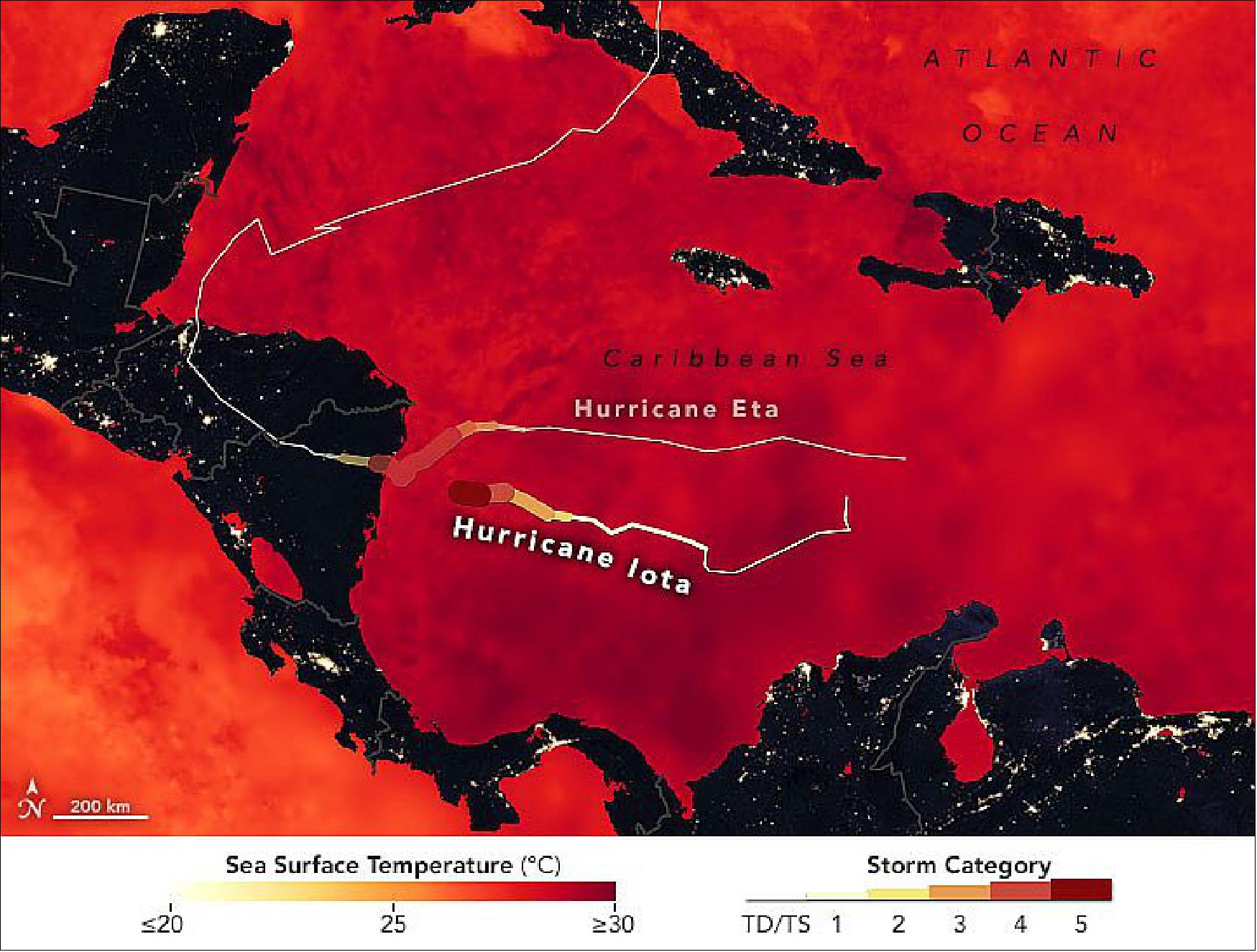
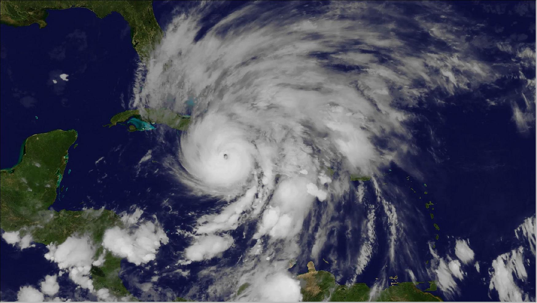
• November 17, 2020: Less than two weeks after being hit by category 4 Hurricane Eta, several Central American countries braced for the arrival of category 5 Hurricane Iota. The U.S. National Hurricane Center (NHC) warned of potentially devastating storm surges and winds, along with torrential rain that will fall upon areas already coping with damaged levees and swollen lakes, reservoirs, and rivers. Iota appeared headed for landfall late on November 16 in northern Nicaragua, likely within tens of kilometers from where Eta hit on November 3, 2020. 14)
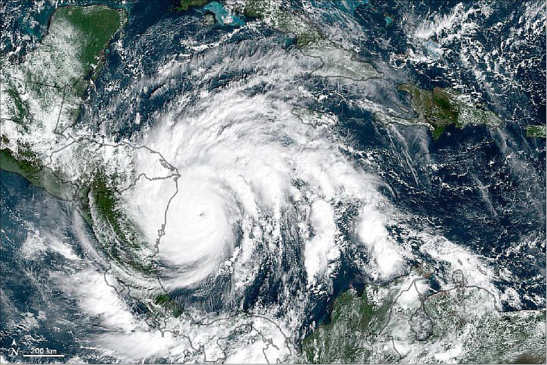
- Iota is the strongest hurricane and 30th named storm of the 2020 Atlantic season, the most since modern record-keeping began. (The previous record of 28 was set in 2005.) It also marked the first time that two hurricanes have formed in the Atlantic in any November. Iota is the 13th storm to reach hurricane strength this year; the average hurricane year brings 11.5 named storms and six hurricanes.
- As of 1 p.m. U.S. Eastern Time on November 16, the NHC had issued hurricane warnings for large portions of coastal Nicaragua and Honduras. Iota had strengthened to a category 5 storm, with sustained winds of 260 km (160 miles) per hour. Forecasters warned of coastal storm surges as high as 4.5 to 6 meters (15 to 20 feet) and rainfall amounts between 250 to 750 mm (10 to 30 inches) across parts of Nicaragua, Honduras, Guatemala, and Belize.
- Tropical storm Iota reached hurricane strength early on November 15. Over the course of 36 hours, wind speeds increased by 160 km (100 miles) per hour—well beyond the threshold of 55 km (35 miles) per hour that meteorologists refer to as “rapid intensification.” The storm grew over particularly warm Caribbean waters, which are known to fuel hurricanes. La Niña conditions in the eastern Pacific may also have played a role, as such events typically reduce wind shear that can break up storms. Iota is the tenth storm to undergo rapid intensification in 2020.
- Research meteorologist Philip Klotzbach of Colorado State University, who is also a hurricane historian, noted on Twitter that Iota is just the second Atlantic hurricane to ever reach category 5 intensity in November. It is also the fifth Atlantic hurricane to form after October 1, 2020. The first 24 named storms of the year produced two major hurricanes; the last six storms have produced four major hurricanes.
- Klotzbach also noted that before 2020, only four category 4 or 5 hurricanes had ever made landfall in Nicaragua. Now two are going to land in the span of two weeks.
Repurposing of the GOES-13 Mission of NOAA to EWS-G1 by the USSF (U. S. Space Force)
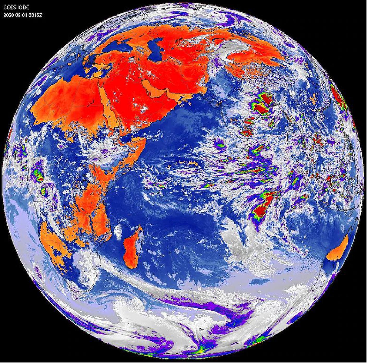
• September 8, 2020: The U.S. Space Force (USSF) has declared Initial Operational Capability of the Electrooptical Infrared Weather System Geostationary (EWS-G1) spacecraft. EWS-G1, formerly known as GOES-13, was transferred to the U.S. Air Force by the National Oceanic and Atmospheric Administration (NOAA) in 2019 under an agreement between the U.S. Air Force and NOAA for Interagency Cooperation on Collection of Spaceborne Environmental Monitoring Data. 15)
Originally launched in 2006, GOES-13 provided operational weather coverage over the United States East Coast for 10 years before being replaced in the GOES-East position by GOES-16. EWS-G1 is the first Department of Defense (DoD) owned geostationary weather satellite. The satellite provides timely cloud characterization and theater weather imagery to DoD in the Indian Ocean region, addressing needs across Central Command (CENTCOM) and other operating theaters.
- The transfer and relocation of EWS-G1 is the culmination of joint efforts between the USSF’s Space and Missile Systems Center, NOAA and NASA (National Aeronautics and Space Administration).
- “EWS-G1 is a prime example of innovation and the leveraging of partnerships. SMC partnered with NOAA and NASA to deliver critically needed Geostationary visible and infrared cloud characterization and theater weather imagery in the Indian Ocean region. This effort demonstrates speed by allowing the spacecraft to be moved and operated in the Indian Ocean region far earlier than a new satellite could be produced and fielded,” said Charlotte Gerhart, SMC’s Production Corps Low Earth Orbit Division chief. “The repurposing of GOES-13, and residual NOAA ground equipment, accomplished the mission at a fraction of the procurement cost of a brand new system.”
- After the relocation maneuver, NOAA and the U.S. Space Force completed a thorough checkout of the EWS-G1 spacecraft and sensors. All criteria were met to declare the system operational and EWS-G1 is now providing weather data to DOD forecasters. NOAA will continue to operate EWS-G1 on behalf of the U.S. Space Force for its remaining life span, from the NOAA Satellite Operations Facility in Suitland, Maryland and Wallops Command and Data Acquisition Station in Virginia.

• January 8, 2018: GOES-13 retired -to make way for next generation of weather imagery! — NOAA’s GOES-13 satellite has captured some of the most notorious weather events in recent U.S. history – from paralyzing blizzards in the Northeast and Midwest, to destructive hurricanes like Sandy in 2012 and last summer’s historic run of Hurricane Harvey, Irma and Maria. 16)
- But with the emergence of the next-generation GOES-16 as NOAA’s new GOES-East satellite, GOES-13, which held the position since April 2010, was powered down on January 8, 2018. It can be reactivated if one of NOAA’s other operational or backup satellites experiences trouble.
- “GOES-13 was a reliable work horse, supplying meteorologists with the crucial imagery and data, which enabled NOAA to provide accurate forecasts and warnings of storms, many of which are in the record books,” said retired Navy Rear Adm. Timothy Gallaudet, acting NOAA administrator.
- A previous NOAA geostationary satellite, GOES-14, also deactivated, will remain NOAA’s primary back-up satellite, and can be activated if either GOES-16 or GOES-15, the current GOES-West satellite, experiences technical difficulties.
- The next next-generation satellite, NOAA’s GOES-S is scheduled for launch on March 1, 2018 and will become the new GOES-West satellite after a checkout and testing phase, which can take up to a year. Forecasters will be able to take advantage of its advanced imagery during that phase-in time. Together, these satellites will enable NOAA to more closely monitor weather systems over North America, South America, and the Atlantic and Pacific Oceans to help protect lives and property.
• On May 24, 2016, GOES-13 was 10 years on orbit. Known as GOES-N prior to launch, GOES-13 has been serving actively as GOES-East since April 2010. It was the first of NOAA's three-axis, body-stabilized geosynchronous environmental satellites and features a variety of enhanced instruments whose capabilities surpass those of earlier GOES satellites. Among them are: 17)
- An improved INR (Image Navigation and Registration) system that uses star trackers, optical devices that measures the position of the stars to help with spacecraft orientation, to provide more stable and accurate Earth-pointing capabilities, decreasing the amount of “shake” in an image.
- An imaging radiometer that uses data obtained from its five channels to continuously produce images of the Earth’s surface, oceans, severe storm development, cloud cover, cloud temperature and height, surface temperature, and water vapor. It allows users to identify fog at night, distinguish between water and ice clouds during daytime hours, detect hot spots (such as volcanoes and forest fires), locate a hurricane eye, and acquire measurements of ground and sea surface temperatures.
- A sounder that provides detailed descriptions of conditions in the atmosphere at any time, allowing meteorologists to deduce atmospheric temperature and moisture profiles, surface and cloud-top temperatures, and ozone distributions. Sounder data is also used in computer models that produce mid-and long-range weather forecasts.
- A space environment monitor that consists of three components — an energetic particle sensor package, two magnetometer sensors, and a solar x-ray sensor — to keep tabs space weather conditions and provide warnings of geomagnetic storms capable of damaging communications and electrical infrastructure on Earth.
As part of the international COSPAS-Search and Rescue Satellite-Aided Tracking (SARSAT) system, GOES-13 carries a transponder that detects signals transmitted by 406 MHz emergency beacons used by planes, ocean-going vessels, and individuals in emergency situations and relays the location data to search and rescuers.
• Oct. 16, 2015: 40th anniversary of GOES-1. On October 16, 1975, NOAA’s first GOES (Geostationary Operational Environmental Satellite) was launched from Cape Canaveral Air Force Station in Florida. Known as GOES-A when it launched, the satellite was designated GOES-1 once operational. 18)
- GOES-1 returned its first image only nine days later on October 25, and quickly became an essential tool used by the NOAA’s National Weather Service.
- Using a Visible/Infrared Spin Scan Radiometer (VISSR), the satellite provided day and night observations of cloud and surface temperatures, cloud heights and wind fields. Although GOES-1 was spin-stabilized, only viewing Earth about 10 percent of the time and providing data in only two dimensions, it gave forecasters their first near-real time look at atmospheric conditions from a fixed location.
- GOES-1 remained active throughout the launches of GOES-2-6, until finally being decommissioned on March 7, 1985.
- The following generations of GOES satellites and their instruments continued to improve, experiencing significant enhancements, and have now provided continuous and accurate imagery and data on atmospheric conditions, solar activity, and Earth’s weather systems for 40 years. Over the decades, the GOES satellites have taken well over 3 million images!
• In March 2012 the following GOES missions are operational: 19)
- GOES-12 provides coverage for South America
- GOES-13 is the operational East spacecraft
- GOES-14 is on-orbit storage
- GOES-15 is the operational West spacecraft.
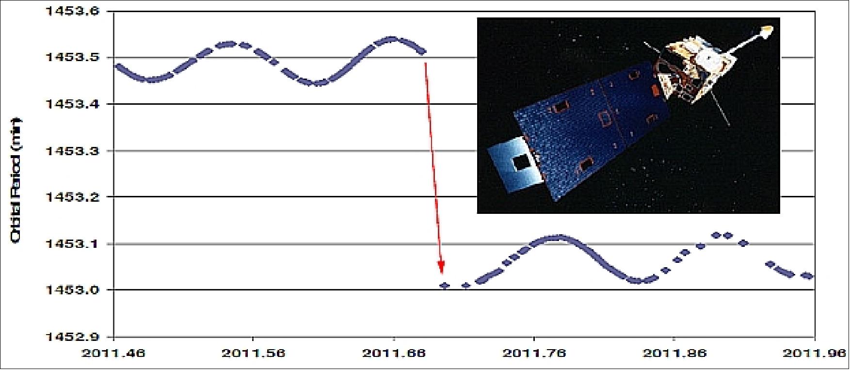
Note: The GOES-10 spacecraft was decommissioned on December 2. 2009. Nearly two years after the GOES-10 spacecraft had been decommissioned and placed in a compliant disposal orbit above GEO, then on Sept. 5, 2011 the orbit of the vehicle was abruptly perturbed: the perigee decreased by 20 km. - The cause is still unknown, but a collision with a small object is a possibility (Figure 10, Ref. 6).
• GOES-10 (located at 60º W) is operating nominally as of 2008, providing coverage for South America. GOES-10 was activated on July 21, 1998 to replace the GOES-9 spacecraft. See GOES-10 status under GOES N, O, P for more details. 20)
• GOES-11: located at 135º W longitude, is the operational West spacecraft as of 2008. The SEM package is operating with degraded performance.
GOES-11 was in orbital storage after launch. As of June 2004, GOES-11 has returned to normal on-orbit mode from the Z-Axis Precession (ZAP) storage mode.
• GOES-12: located at 75º W longitude, is the operational East spacecraft. The SEM package is operating with degraded performance. The SXI is not operational.
An anomaly of the X-ray positioning electronics box occurred on April 16, 2007. As a consequence, the GOES-12 S/C cannot point the XRS and SXI at the sun, nor can it process the XRS data that normally would pass through it. Hence, the XRS and SXI data are not distributed anymore starting at April 12, 2007. 21)
• GOES-9 (West), with a launch in 1995, was put into a storage mode 2002. As of April 2003, GOES-9 is providing a backup service for Japan's GMS-5 satellite (on NOAA loan to JMA), GOES-9 is located at 155º E for the backup service. The replacement follow-on S/C (to GMS-5), MTSAT-1R (Multifunctional Transportation Satellite-1 Replacement), was launched on Feb. 26, 2005 (long launch delays due to H-IIA launch vehicle problems). GOES-9 still has sounding and limited imaging capabilities providing a supply of data comparable to that of the GMS-5. As of 2007, GOES-9 still serves in a backup function at 160º East.
• GOES-8 (formerly GOES East). It operated until 2003 and was relocated to 165º E on Aug. 24, 2003 as backup for GOES-9. GOES-8 was decommissioned by NOAA on May 5, 2004.
• GOES-13, with a launch on May 24, 2006, was placed in on-orbit storage on Jan. 5, 2007. It will remain in storage until either thruster fuel is depleted or instrument failure occurs on one of the two currently operational GOES satellites. 22)
Sensor Complement
Starting with GOES-I (GOES-8 on-orbit) each satellite carries two separate so-called second generation instruments, an imager and a sounder, providing simultaneous imaging and sounding capabilities. 23)
GOES Imager
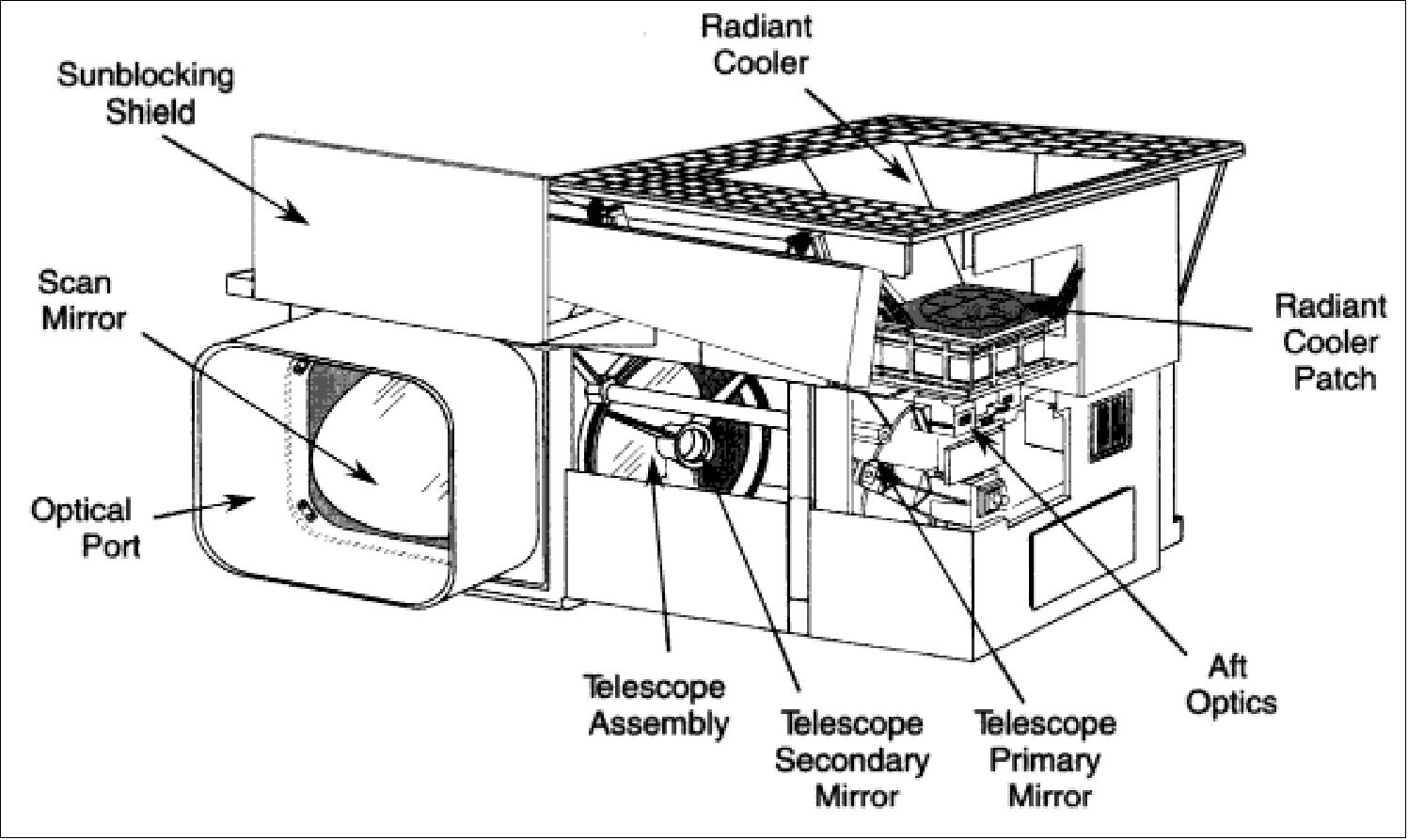
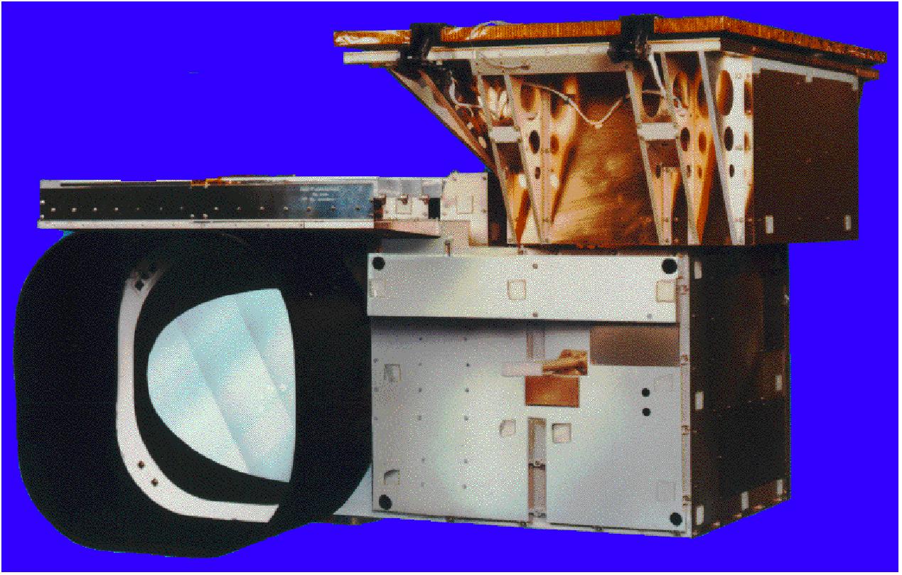
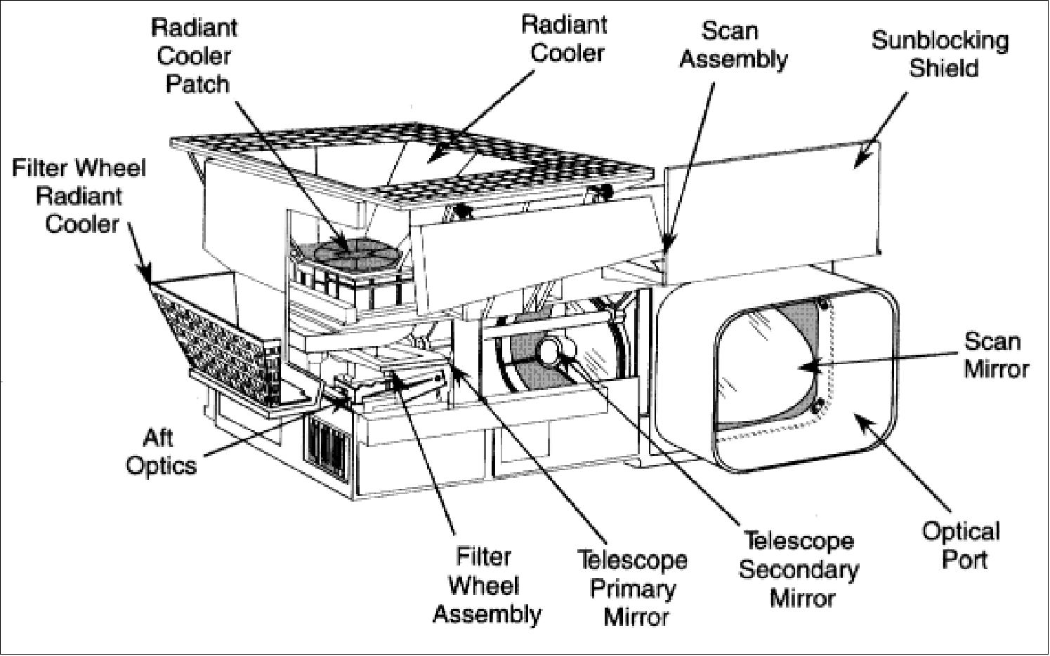
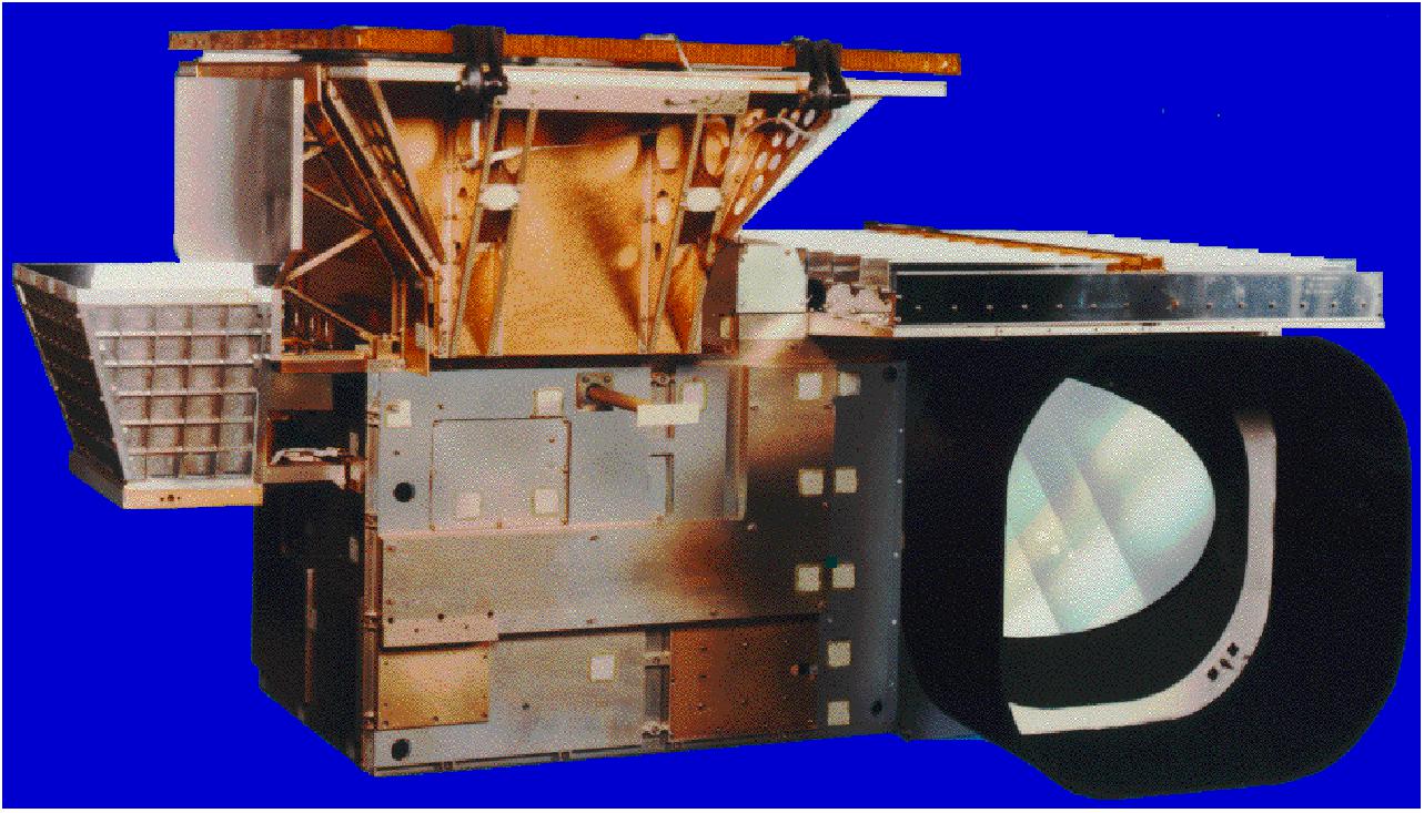
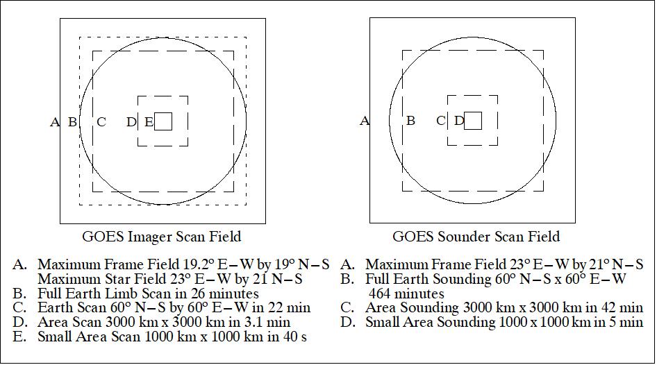
The GOES imager is a multispectral imaging radiometer, built by ITT A/CD of Fort Wayne, IN. Objective: Operational meteorology and climatology (one channel in the VIS and four channels in the IR range). The GOES Imager measures radiant and solar-reflected energy from sampled areas of the Earth. The instrument consists of electronics, power supply, and sensor modules. The sensor module containing the telescope, scan assembly, and detectors, is mounted on a baseplate external to the spacecraft, together with the shields and louvers for thermal control. By means of a servo-driven, two-axis gimballed mirror scan system in conjunction with a Cassegrain telescope, the imager's channels can simultaneously sweep an 8 km north-to-south swath along an east-to-west/west-to-east path, at a rate of 20º (optical) east-west per second. Resolution: = 1km in the VIS range and 4 km in the IR region (except for the 6.5-7.0 µm MWIR channel at 8 km resolution). A normal full Earth disk scan (18º x 18º) is done in 25 minutes (a 3000 km x 3000 km area can be scanned in 3.1 minutes, a 1000 km x 1000 km area in 40 seconds). The instrument can produce full-Earth disk images, sector images that contain the edges of the Earth, and various sizes of area scans completely enclosed within the Earth scene using a new flexible scan system. Scan selection permits rapid continuous viewing of local areas for monitoring of regional phenomena. The key features of the imager are summarized in Tables 4 and 7. The pointing accuracy of the GOES Imager is within a 4 km radius at nadir. 24) 25) 26)
Spectral | 1 | 2 | 3 | 4 | 5 |
Prime measurement purpose | Cloud Cover | Nighttime Clouds, Fires, Volcanoes | Water Vapor | Surface Temp. | Low-level moisture, clouds |
Wavelength (µm) | 0.55 - 0.75 | 3.80 - 4.00 | 6.50 - 7.00 | 10.20 - 11.20 | 11.5 - 12.50 |
Measurement Range | 1.6 to100% | 4 to 320 K | 4 to 320 K | 4 to 320 K | 4 to 420 K |
S/N or NEDT | 150:1 | 1.4 K at 300 K | 1.0 K at 230 K | .35 K at 300 K | .35 K at 300 K |
Detector Type | Silicon | InSb | HgCdTe | HgCdTe | HgCdTe |
Spatial resolution (µrad) | 28 (1 km x 1 km at nadir) | 112 (4 km x 4 km at nadir) | 224 (8 km x 8 km at nadir) | 112 (4 km x 4 km at nadir) | 112 (4 km x 4 km at nadir) |
Channel No | Spectral Range (µm) | Measurement Range | Measurement Objective |
1 | 0.55 - 0.75 | 1.6 to100% albedo | Cloud cover |
2 (GOES-I/J/K) | 3.80 - 4.00 | 4 - 320 K | Nighttime clouds (space-340 K) |
3 (GOES-I/J/K/L) | 6.50 - 7.00 13.0 - 13.7 | 4 - 320 K | Water vapor (space-290 K) |
4 | 10.20 - 11.20 | 4 - 320 K | SST and water vapor (space-335 K) |
5 (GOES (I/J/K/L) | 11.50 - 12.50 | 4 - 320 K | SST and water vapor (space-335 K) |
Spectral | 1 | 2* | 3* | 4 | 5 |
Wavelength (µm) | 0.55 - 0.75 | 3.80 - 4.00 | 6.50 - 7.00 | 10.20 - 11.20 | 11.5 - 12.50 |
Product | |||||
Clouds | x | x | x | x | x |
Water vapor |
|
| x | x | x |
Surface temperature |
|
| 0 | x | 0 |
Winds | x |
| x | x |
|
Albedo + IR flux | x |
| 0 | x | 0 |
Fires + smoke | x | x |
| 0 | 0 |
Legend to Table 6:
• * = new operational data
• x = primary channel
• 0 = secondary channel
GOES Sounder
The GOES sounder is an infrared sounder for operational meteorology and climatology (19 channel discrete-filter radiometer). Objective: atmospheric soundings. Data products are: vertical temperature and moisture profiles, layer mean temperature and moisture, cloud height and amount, total precipitable water, surface temperatures, lifted index, gradient and wind derived from horizontal temperature and moisture fields. Resolution: 8 km. The GOES Sounder is of HIRS/2 heritage providing similar instrument operation and performance. A filter wheel rotating ten times per second provides for data sampling at ten steps per second (the filter wheel brings the spectral filters into the optical path of the detector array, thereby providing channel definition). The detector filter arrangement makes use of four spectral bands (see Table 8). The Sounder's multi-element detector array assemblies simultaneously sample four separate fields or atmospheric columns, i.e., four detectors are simultaneously irradiated in each band, providing an output from four Instantaneous Geometric Fields of View (IGFOV). In this manner the system can sample four 8 km IGFOV each 0.1 seconds. - The data products of the sounder are planned for use in numerical weather forecast models. They provide data coverage in oceanic regions lacking conventional observations.
Both Imager and Sounder employ a servo-driven, two-axis gimballed mirror systems (whiskbroom type) in conjunction with a 31 cm Cassegrain telescope (separate sensors with independent operation). Each instrument has a flexible scan control, enabling coverage of small areas as well as global scenes (Earth's full disk), and close-up, continuous observations of severe storms.
Feature | GOES Imager | GOES Sounder |
Optical aperture | 31.1 cm | 31.1 cm |
Telescope type | Cassegrain | Cassegrain |
Total step & sample time | N/A | 0.1 s (0.2 s and 0.4 s optional) |
Methods of scan | 2-axis, continuous, | 2-axis, step & dwell; E/W 280 µrad steps; N/S 1120 µrad steps (optional 2240 µrad steps, 0.2 s dwell) |
Scan rate | 20º/s optical | 40 soundings/s |
Slew rate | 10º/s mechanical | 10º/s mechanical |
Spatial resolution (µrad) | VIS = 28, Ch. 2,4, & 5 = 112, | all channels = 242 µrad (diameter) |
Sampling | 1.75/IGFOV VIS, Ch. 2, Ch. 4 & Ch. 5 3.5/IGFOV Ch. 3 | 4 IGFOVs sampled simultaneously |
Sampling rate | 183.3 µs/pixel (IR), | 0.1 s |
Chan. co-registration | ± 28 µrad | Within 22 µrad of channel 8 |
Star sensing | Uses visible array SNR 6 for 4th mag stars (400 samples) | Separate visible array SNR 6 for 4th mag stars (each sample) |
Data output | 10 bit quantization | 13 bit quantization |
Data rate | 2.6208 Mbit/s | 40 kbit/s |
Data format | NRZ-S, PN code | NRZ-S, PN code |
Patch temperature | Regulated at 94 K, 101 K or 104 K | Regulated at 94 K, 101 K or 104 K |
Time between space looks | 2.2 s large frame | 2 min |
Time between BB calibrations | 10-30 min (can override or inhibit) | 20 min (can override or inhibit) |
Priority frame select | 1 level normal; 2 levels priority | 1 level normal; 2 levels priority |
Channel (detector, range) | Center Wavelength | NEΔN | Measurement Objective |
1 (HgCdTe, longwave) | 14.71 | 0.66 | Temperature Sounding |
8 (HgCdTe, midwave) | 11.03 | 0.16 | Surface Temperature |
13 (InSb, shortwave) | 4.57 | 0.013 | Temperature Sounding |
19 (Silicon (visible) | 0.70 | 0.10% Albedo | Cloud |
Silicon (Star Sense) | 0.65 | 6:1 SNR | 4th magnitude stars |
An onboard `Image Navigation and Registration' (INR) system provides good pointing accuracy, i.e. geographical location capability of the imager and sounder pixels in near real-time. The INR system removes the apparent image-to-image motion resulting from orbital motion, satellite attitude deviations, and satellite thermal distortions. This is achieved by continuously steering the instrument scan mirrors to compensate for this motion. Compensation signals are generated in the attitude and orbit control system based on predicted orbits and attitude parameters that are transmitted to the satellite at least once each day from a ground station. The parameters are generated using image landmarks, star views, and satellite range data collected throughout the day. 27)
Product Type | Vert. Resolution | Horiz. Resolution | Absolute Accuracy | Relative Accuracy |
Temperature |
|
|
|
|
Moisture |
|
|
|
|
Cloud |
|
|
|
|
Ozone |
|
|
|
|
IR Flux | total | 50 km | 10 W m-2 | 3 W m-2 |
GOES SEM (Space Environment Monitor) Instruments
In addition, the GOES I-M missions fly the SEM (Space Environment Monitor) instrument package of NOAA/SEC (Space Environment Center). SEM is an operational NOAA instrument package with the objective to provide “space weather” on a regular basis to the user community by measuring the solar wind particle flux and its variations. The package is provided by NOAA/SEC in Boulder, CO.
The SEM instrument package provides data which are processed by SEC (Boulder CO) of NOAA in near real-time for space environment forecasts. The SEM instruments survey the sun and monitor the solar-terrestrial electromagnetic environment that affects a number of Earth activities [operational reliability of ionospheric radio (satellite communications, navigation systems), over-the-horizon radar, electric power transmission, crews on-board of high-altitude aircraft and space stations].
Each SEM package is composed of four separate sensor systems: two energetic particle sensors (EPS, HEPAD), a magnetometer, and a solar soft X-ray sensor. Starting with GOES-M (GOES-12, launch July 23, 2001) the SEM package was extended by a fifth instrument, the SXI (Solar X-Ray Imager). - Note: the GOES series SEM package differs considerably from the POES series SEM package.
EPS (Energetic Particle Sensor)
Objective: monitoring solar protons and alpha particles produced during flares, and continuous monitoring of electrons at geostationary orbit. Measurement in seven channels for high proton fluxes, six channels for alpha particle fluxes, and in three channels for electron flux (note: electron fluxes were not measured from GOES-6 and GOES-7).
Channel Designation | Particle Type | Nominal Energy Range (MeV) | GOES-7 Nominal |
P1 | Proton | <= 0.8 - 4 | 0.6 - 4.2 |
A1 | Alpha | 4 - 10 | 3.8- 9.9 |
E1 | Electron | => 0.6 |
|
HEPAD (High Energy Proton and Alpha Particle Detector)
Objective: monitoring the very high energy protons and alpha particles in large solar flares, and continuous monitoring of galactic cosmic rays. HEPAD uses the phenomenon of Cerenkov radiation which occurs when an incident particle travels at speeds greater than the local speed of light in a high refractive index material, in this case fused silica.
Note: EPS and HEPAD are functionally identical to those flown on previous GOES satellites, except for the additional two electron channels and a reduced entrance aperture of the D4 dome detector.
Channel Designation | Particle Type | Nominal Energy Range (MeV) | GOES-7 Nominal |
P8 | Proton | 350 - 420 | 365 - 430 |
A7 | Alpha | 2560 - 3400 |
|
Magnetometer of SEM Package
Objective: measurement of the magnitude and direction of the ambient magnetic field. Three boom-mounted orthogonal sensors for the three components. Sensitivity of 0.2 nT, measurement range of ±1000 nT.
XRS (Solar X-Ray Sensor)
Objective: measurement of the solar X-ray spectrum in two broad energy bands: 1-8 and 0.5-4 Å. The X-ray sensor continuously looks into the sun direction. The collimator and ion chamber assembly are mounted on a single axis positioner, which in turn is mounted on the S/C solar yoke. 28)
Note: XRS is similar to the previously flown designs; however, it is continuously pointed at the sun by virtue of being mounted on the solar array yoke, and on top of a positioner that tracks the sun in the north-south direction.
SXI (Solar X-ray Imager)
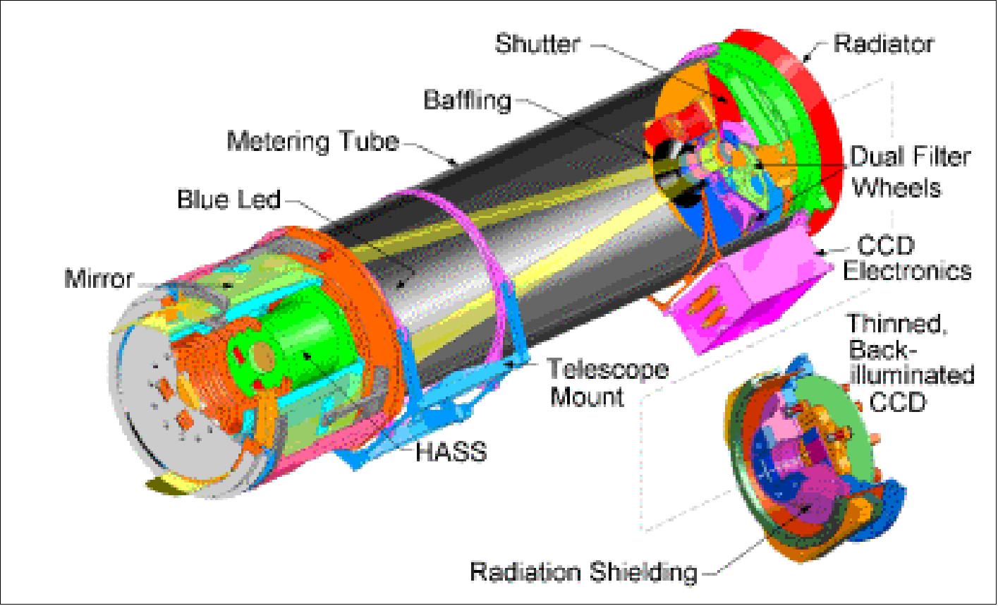
SXI is part of the SEM subsystem starting with GOES-M (GOES-12). The instrument is a broadband imager operating in the 0.6-6.0 nm bandpass (soft X-ray region). It has a full width at half maximum (FWHM) of ~10 arcsec sampled with 5 arcsec pixels in a 512 x 512 detector array. The objective of SXI is the provision of full-disk solar imagery at a 1 minute intervals on a continuous basis (around the clock). This feature provides a sensitive means of detecting the beginning of solar flares - explosive events on the sun's surface that are fueled by the intense magnetic fields that accompany sunspots. Solar activity in turn causes disturbances in the solar wind which propagates to Earth disturbing its local magnetic field. The early warning function is important because the solar flares affect not only the safety of humans in high-altitude missions, such as the ISS crew, but also communication systems. 29) 30) 31) 32)
The SXI employs a small telescope that makes use of advanced technology and grazing incidence optics to allow it to see the sun's outer atmosphere or corona in X-rays. Observational flexibility is provided in form of recurring sequences of images. Sequences can be selected or modified based on solar activity levels. Examples are: 33)
• Locate coronal holes for geomagnetic storm forecasts
• Detect and locate flares for forecasts of solar energetic particle (SEP) events related to flares
• Monitor changes in the corona that indicate coronal mass ejections (CMEs)
• Detect active regions beyond east limb for F10.7 forecasts
• Analyze active region complexity for flare forecasts.
Imaging exposure times |
|
Spacecraft SXI boresight pointing (to the center of the solar disk) | Within 3 arcmin elevation, |
Spectral sensitivity (integration time 100 ms) |
|
Dynamic range | 1000 when measured with monochromatic illumination at 44.7 Å |
Data quantization | 10 bits (linear or logarithmic channels) |
Point response (image on pixel array) Percentage of total energy incident on detector falling inside |
|
Background: SEM-1 instruments were initially introduced on satellites in geostationary orbit starting in 1974. The SEM package of the GOES series was upgraded with the introduction of SXI (Solar X-ray Imager) instrument on GOES-12 (launch July 23, 2001) and the follow-up spacecraft of the series. The SXI instrument is providing space weather forecasters with near real-time imagery of the sun's explosive atmosphere, helping them issue timely warnings when solar activity might harm spaceborne and/or ground-based assets. NOAA/SEC receives the data, which is being shared with the US Air Force, and NASA in real-time. Products available to the research community are described as Level 0 (raw data) and Level 1.
SXI as flown on GOES-12 is considered the prototype instrument; it was developed by NASA/MSFC (Marshall Space Flight Center) and it employs a detector of the type MCP (Microchannel Plate).
The follow-on SXI instruments (GOES-N, -O, -P) are being built at LMSAL (Lockheed Martin Solar Astrophysics Laboratory) for NOAA/SEC; they employ CCD detectors (thinned, back-illuminated) instead of the MCPs, providing improved sensitivities. Both types of instruments provide the following features: a) detector array size of 512 x 580 pixels, b) 5 arcsec pixels, c) bandpass of 0.6-6.0 nm. The Lockheed instrument has the capability to interleave additional images and to respond to solar flares and other events autonomously.
S&RSAT (Search and Rescue Satellite) Payload
S&RSAT on GOES, referred to as GEOS&R (Geostationary Search and Rescue):34)
S&R capability (the distress signal detection function) was first introduced on GOES-7 as a research/demonstration program to introduce the technology into the COSPAS-S&RSAT system. It is now an operational GOES service of the GOES-I-M series.
The S&RSAT design differs somewhat between GOES-7 and the new GOES-8 series. On GOES-7, -8, and -9, S&RSAT receives signals with the GOES UHF antenna. On GOES-7, both the DCP data and the S&RSAT data are transmitted back through the same downlink transmitter, the S-band antenna. The GOES-7 downlink frequency is 1698 MHz. On GOES-8 (and follow-on satellites), the S&RSAT downlink transmission is through a separate S&RSAT (L-band) helix antenna. On GOES-8, the uplink frequency for S&RSAT is 406 MHz and the downlink frequency is 1544.5 MHz; and for the DCP reporting mode (DCPR), the uplink frequency is 401 MHz with the DCPR downlink at 1694 MHz. - The GEOS&R system is also being considered for future Meteosat as well as for the GMS satellite series.
DCS (Data Collection System) on GOES Spacecraft
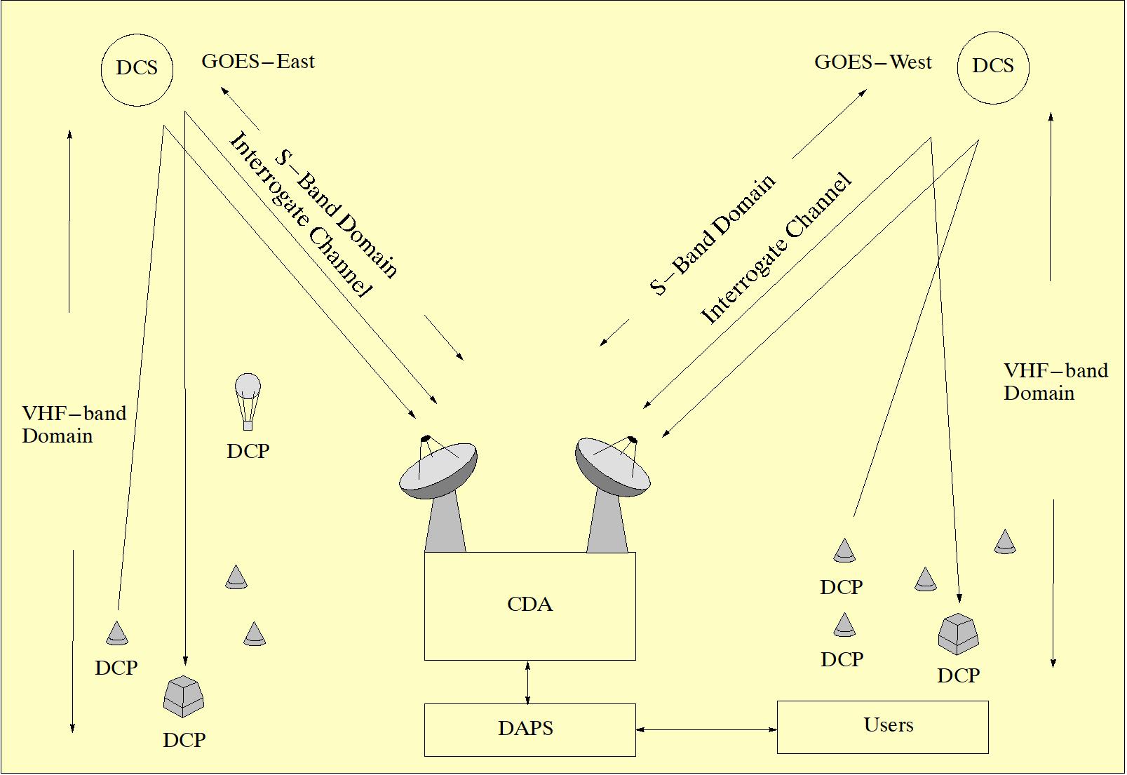
The DCS on NOAA-GOES satellites provides an operational data collection service for a large number of land-, air- and sea-based data collection platforms (DCPs) in the ground segment. Geostationary satellites (like GOES) offer the advantage of continuous coverage; however, their coverage is not global, but limited to the GOES service region. The overall system is composed of the following subsystems: 35) 36) 37)
1) The space segment: a DCS platform on two operational GOES satellites (GOES-East, and GOES-West). Each GOES spacecraft is equipped with two DCS transponders, one active and one as backup.
2) The deployed Data Collection Platforms (DCPs) in the ground segment
3) The NOAA/NESDIS DCS ground receive system CDA (Command and Data Acquisition Station) at Wallops Island, Virginia.
4) The DAPS (Data Collection System Automatics Processing System) at CDA.
The Space Segment: DCS
The DCS onboard GOES uses the GOES S/C for the relay of data from remotely located in-situ sites at or near the Earth's surface to properly equipped receiving stations in radio view of the GOES satellites. The onboard DCS gathers and relays environmental data transmissions that originate at remote automatic Data Collection Platforms (DCPs) for obtaining in situ data. The DCS collected data are retransmitted from the satellite to small ground-based regional data utilization centers. The system also allows for the retransmission of narrow-band WEFAX (Weather Facsimile) data to existing small, ground-based APT (Automatic Picture Transmission) receiving stations from a larger facility.
Each GOES provides an RF link between the DCP and CDA. They up-convert DCP data from UHF (401.9 MHz) to S-band (1694.5 MHz) for transmission to CDA, and down-convert the CDA -DCP interrogate signal from S-band (2034.9 MHz) to UHF (468.8 MHz).
The DCS uses 400 kHz of satellite transponder bandwidth. This bandwidth is subdivided (by frequency division multiplexing) into 200 domestic channels with a 1.5 kHz channel separation (channels 1-200), and 33 international channels (channels 202 - 266, even numbered only) with a 3 kHz channel separation. The 33 international channels are common to those of METEOSAT, GMS and GOMS spacecraft.
The DCS has the capacity for handling at least 25,320 messages from DCP sites via the spacecraft transponder in each one-hour period. This figure is based on the present capability to assign 30-second transmission windows for each of the 200 domestic channels, i.e., 120 windows per hour over 200 channels (120 x 200 = 24,000), plus 33 international channels (33 x 40 = 1320), 1320+24,000=25320. - With advances being made in the stability and accuracy of timing oscillators, transmission windows of 15 seconds may become standard in the future. The data transmission rate for all operational modes used to be 100 bit/s in 1995. Prototype 300/1200 bit/s DCPs were developed and introduced in 1996.
Ground Segment
All DCPs serviced by GOES must be type-certified by NOAA-NESDIS. The types available to the user community have the following functional capabilities:
• Self-timed DCPs (this is the most common mode of use)
• Self-timed and random reporting DCPs
• Random reporting DCPs
• Interrogated DCPs
• Self-timed and interrogated DCPs
• Random and interrogated DCPs
1) Self-timed DCPs. - These are simple platforms containing a transmitter and a pre-programmed self-timer to report at a specific time and intervals to the GOES. The sensor measuring cycle is independent of the DCP reporting cycle. Sensor data may be recorded at the DCP prior to a message transmission to GOES. The reporting frequency from a DCP may vary from a few minutes to a few hours.
2) Self-timed and random reporting DCPs. - Same functionality of 1) with the addition of capability of transmitting over a secondary channel when environmental conditions require more frequent reporting than offered under self-timed operation.
3) Random reporting DCPs. - The platform contains a transmitter that broadcasts at random time (threshold reporting, set by the user). During normal periods a random reporting DCP is expected to report up to three times per day that it is properly functioning.
4) Interrogated DCPs. - Scheduled transmissions initiated from the CDA at NESDIS (the schedule is stored at CDA). This type of DCP contains a receiver and transmitter. The receiver detects its own DCP ID upon message reception from CDA. Upon detection of its ID the DCP transmits all data accumulated since the last reporting sequence. Interrogated DCPs may be interrogated as often as every 5 minutes or as infrequently as once per day. In addition some interrogated DCPs have a second or alert reply channel that may be used for threshold reporting. Interrogated DCPs may be reconfigured by CDA command when requested by the user.
5) Self-timed and interrogated DCPs. - This type of DCP operates in a self-timed mode under normal conditions. When a message is not received at the DCP's normal reporting time, an interrogation address is sent via the DAPS to the DCP and a reply is expected over the interrogate reply channel.
6) Random and interrogated DCPs. - This mode of operation is used to monitor special events (such as seismic events). When the event condition reaches a pre-set level, a random transmission is sent through the GOES S/C. Only the DCP ID (address) is transmitted. When the ID is received by the DCS system at the CDA, an interrogate ID is transmitted through the GOES S/C. The interrogate ID can be used as a notification of the event, to change a DCP's mode of operation, or to cause certain functions to be performed.
NOAA/NESDIS Ground Segment
The NOAA ground system consists of the RF front-end equipment and the DCS computer equipment or DAPS (GOES DCS Automatic Processing System). The messages received from the DCPs are routed to the DAPS, which provides all required processing and dissemination functions including data storage and distribution to the user community.
DCS Access Method
Data transmission from a DCP in the ground segment to the DCS on-board GOES is generally initiated (i.e. self-triggered) by the ground segment DCPs (except for the few interrogated DCPs). All of the 200 channels on-board GOES are in listening mode, being available all the time. The assigned transmission times of the DCPs are actually time intervals (slots) of 1 minute duration.
As of the end of 1993, NOAA service records list 7728 activated DCPs being serviced by GOES S/C, out of a total of 11,927 DCPs that are assigned to the GOES user community at large.38) - There are six DCPs of the type `interrogated' serviced by NOAA/NESDIS and used for seismic and tsunamic warning. In addition there are another 15 DCPs which use the interrogate mode as backup to the self-timed mode and to command these DPCs to perform specific functions under specific conditions.
References
1) W. P. Menzel, J. F. W. Purdom, “Introducing GOES-I: The first of a Generation of new Geostationary Operational Environmental Satellites,” Bulletin of the American Meteorological Society, Vol. 75 No. 5, May 1994, pp. 757 -781
2) http://www.oso.noaa.gov/goes/
3) GOES brochures, URL: http://goes.gsfc.nasa.gov/text/goesimbroch.html
4) http://goespoes.gsfc.nasa.gov/goes_npbooklet/booklet.pdf
5) “NOAA retires GOES-7 after 25 years as a weather and communications satellite,” NOAA, April 12, 2012, URL: http://www.noaanews.noaa.gov/stories2012/20120412_goes7.html
6) N. Johnson, “USA Space Debris Environment, Operations, and Policy Updates,” Proceedings of the 49th Session of UNCOPUOS-STSC (UN Committee on the Peaceful Uses of Outer Space-Scientific and Technical Subcommittee), Vienna, Austria, Feb. 6-17, 2012, URL: http://www.oosa.unvienna.org/pdf/pres/stsc2012/tech-26E.pdf
7) J. Savides, “Geostationary Operational Environmental Satellite GOES I-M,” System Description, Space Systems/Loral, Palo Alto, CA, Dec. 1992
8) “The GOES I-M Series Satellites - A brief description and Status Report,” NOAA draft paper, March 1993
9) http://rsd.gsfc.nasa.gov/goes/text/goes.databook.html
10) “GOES I-M Data Book” by Space Systems/Loral
11) http://goes.gsfc.nasa.gov/text/goestechnotes.html#spacecraft
12) W. P. Menzel, J. F. W. Purdom, “Introducing GOES-I: The First of a New Generation of Geostationary Operational Environmental Satellites,” BAMS (Bulletin of the American Meteorological Society), Vol. 75, No 5, May 1994, pp. 757-781
13)) http://science.hq.nasa.gov/missions/satellite_47.htm
14) ”Dangerous Hurricane Iota Sets Late-Season Records,” NASA Earth Observatory, 17 November 2020, URL: https://earthobservatory.nasa.gov/images
/147539/dangerous-hurricane-iota-sets-late-season-records
15) ”USSF and NOAA Begin Joint Operations of Infrared Weather Satellite,” Schriever AFB, 8 September 2020, URL: https://www.schriever.af.mil/News/Article-Display/Article/
2340039/ussf-and-noaa-begin-joint-operations-of-infrared-weather-satellite/
16) ”NOAA Retires GOES-13 Satellite After 10 Years of Stellar Service,” NOAA/NESDIS, 8 Jan. 2018, URL: https://www.nesdis.noaa.gov/content/noaa-retires-goes-13-satellite-after-10-years-stellar-service
17) ”GOES-13 Turns 10,” NESDIS News Archive, May 24, 2016, URL: http://www.nesdis.noaa.gov/news_archives/goes_13.html
18) ”40 Years of GOES: The Anniversary of GOES-1,” NOAA/NESDIS, Oct. 16, 2015, URL: http://www.nesdis.noaa.gov/news_archives/40_years_of_goes_the_anniversary_of_goes1.html
19) GOES status of March 23, 2012, URL: http://www.oso.noaa.gov/goesstatus/
20) http://www.oso.noaa.gov/goesstatus/
21) http://www.sec.noaa.gov/Data/goes.html
22) http://www.spaceweather.noaa.gov/sxi/goes13/info/G13_past_status.html
23) “GOES Users' Conference Report,” May 22-24, 2001, Boulder, CO, USA, URL: http://www.goes-r.gov/downloads/GOES_Users_ConferenceI/GUC_Report.pdf
24) K. A. Hursen, et al., “The GOES Imager: overview and evolutionary development,” SPIE, Vol. 2812, pp.160--173, 1996
25) http://noaasis.noaa.gov/NOAASIS/ml/imager.html
26) http://ww2010.atmos.uiuc.edu/(Gh)/guides/rs/sat/goes/img.rxml
27) Note: Image navigation refers to the determination of the location of a pixel within an image in terms of Earth's longitude and latitude; registration refers to stability of maintaining pointing of each pixel to a specific Earth location within an image and between repeated images.
28) P. L. Bornmann, D. Speich, J. Hirman, L. Matheson, R. Grubb, H. Garcia, R. Viereck, “GOES x-ray sensor and its use in predicting solar-terrestrial disturbances,” 'GOES-8 and Beyond,' Edward R. Washwell; Ed., Proceedings of SPIE, Vol. 2812, Oct. 1996, pp. 291-298
29) S. Hill, V. Pizzo, C. Balch, D. Biesecker, P. Bornmann, E. Hildner, L. Lewis, R. Grubb, M. Husler, K. Prendergast, J. Vickroy, S. Greer, T. Defoor, D. Wilkinson, R. Hooker, P. Mulligan, E. Chipman, H. Bysal, J. Douglas, R. Reynolds, J. Davis, K. Wallace, et. al., “The NOAA Goes-12 Solar X-Ray Imager (SXI) 1. Instrument, Operations, and Data,” Solar Physics, Vol. 226, No 2, Feb. 2005, pp. 255-281
30) V. J. Pizzo, S. M. Hill, J. M. Davis, “Coronal Imaging with the GOES-12 SXI Instrument,” AGU (American Geophysical Union) Fall Meeting 2001, Dec. 10-14, 2001, San Francisco, CA, USA
31) GOES DataBook: Solar X-ray Imager, URL: http://goes.gsfc.nasa.gov/text/databook/section06.pdf
32) B. McGehan, “SXI - providing snapshots and movies of the sun for solar forecasters,” URL: http://www.research.noaa.gov/spotlite/archive/spot_sxi.html
34) M. J. Nestlebush, “The Geostationary Operational Environmental Satellite Data Collection System,” NOAA Technical Memorandum NESDIS 40, June 1994
35) “The Geostationary Operational Satellite Data Collection System,” NOAA Technical Memorandum NESDIS 2, June 1983
36) “Users Guide for Random Reporting - An Introduction to GOES Random Reporting Services,” NOAA, April 1985
37) User Interface Manual, Version 1.1, for the `Data Collection System Automatic Processing System (DAPS),' Integral Systems Inc., Sept. 1990
38) Information provided by M. J. Nestlebush of NOAA/NESDIS
The information compiled and edited in this article was provided by Herbert J. Kramer from his documentation of: ”Observation of the Earth and Its Environment: Survey of Missions and Sensors” (Springer Verlag) as well as many other sources after the publication of the 4th edition in 2002. - Comments and corrections to this article are always welcome for further updates(eoportal@symbios.space).
Spacecraft Operational Status Sensor Complement Ground Segment References Back to Top