Himawari-8 and 9
EO
Atmosphere
Ocean
Cloud type, amount and cloud top temperature
Himawari-8 and Himawari-9 are identical geostationary Japanese weather satellites, owned and operated by JMA (Japanese Meteorological Agency), launched in October 2014 and November 2016 respectively. The satellites aim to provide typhoon, rainstorm and weather forecasting for the East Asia, Japan and West Pacific region.
Quick facts
Overview
| Mission type | EO |
| Agency | JMA |
| Mission status | Operational (nominal) |
| Launch date | 07 Oct 2014 |
| Measurement domain | Atmosphere, Ocean, Snow & Ice |
| Measurement category | Cloud type, amount and cloud top temperature, Aerosols, Surface temperature (ocean), Atmospheric Humidity Fields, Sea ice cover, edge and thickness, Snow cover, edge and depth, Atmospheric Winds |
| Measurement detailed | Cloud top height, Cloud cover, Aerosol optical depth (column/profile), Cloud type, Cloud imagery, Sea surface temperature, Sea-ice cover, Snow cover, Wind profile (horizontal), Volcanic ash, Water vapour imagery |
| Instruments | AHI, Himawari Comms, Himawari DCS |
| Instrument type | Imaging multi-spectral radiometers (vis/IR), Communications, Data collection |
| CEOS EO Handbook | See Himawari-8 and 9 summary |

Summary
Mission Capabilities
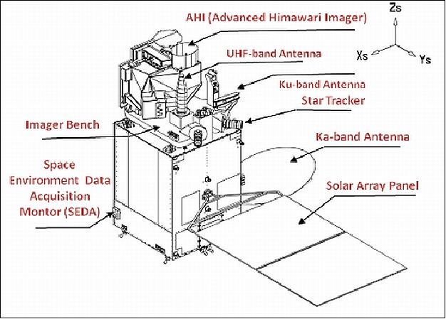
Himawari-8 and 9 each carry two instruments:
- AHI (Advanced Himawari Imager)
- SEDA (Space Environment Data Acquisition Monitor).
AHI is a multipurpose moderate resolution imager, that aims to provide imagery for weather watch, NWP (Numerical Weather Prediction) utilisation and environment monitoring, as well as wind derivation by tracking clouds and water vapour features.
SEDA is an energetic particle spectrometer that aims to measure the radiation the satellites are exposed to in orbit.
Performance Specifications
AHI operates across 16 channels, in the VIS, NIR, SWIR, MWIR and TIR (Visible, Near Infrared, Shortwave Infrared, Medium Wave Infrared, and Thermal Infrared) regions, with central wavelengths 470 nm - 13.30 µm and bandwidths of 20 nm - 0.37 µm. Its spatial resolution ranges from 0.5 km to 2.0 km and has full disk coverage in ten minutes.
SEDA is capable of measuring the fluxes of protons in the range 15 - 100 MeV and electrons in the range 0.2 - 5 MeV, with a FOV (Field of View) of ±39.35° for protons and ±78.3° for electrons.
Both Himawari-8 and 9 operate in geostationary orbits with an altitude of approximately 35,800 km, and a longitude of approximately 140.7° East.
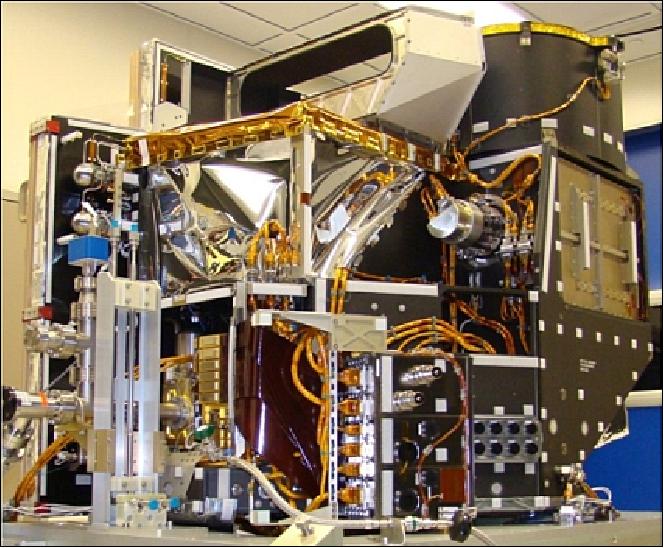
Space and Hardware Components
The Himawari-8 and 9 buses were manufactured by MELCO (Mitsubishi Electric Corporation), according to identical specifications. The spacecraft has dimensions 5.2 x 8.0 x 5.3 m, and a launch mass of approximately 3500 kg.
The buses house the ADCS (Attitude Determination and Control Subsystem), consisting of a Coarse Sun Sensor, a Star Tracker, an IRU (Inertial Reference Unit), a Gyroscope for attitude sensing and an RWA (Reaction Wheel Assembly), for actuation.
Also carried aboard the satellites, are the EPS (Electrical Power Subsystem), and the MDHS (Mission Data Handling Subsystem), which connect with the AHI instrument using the SpaceWire interface and process the data from the instrument into telemetry. The spacecraft uses Ku-band for TT&C (Tracking, Telemetry and Control) transmissions with an uplink rate of 500 bit/s and a downlink data rate of 15.36 kbit/s, while payload data is transmitted in Ka-band, with a data rate of 66 Mbit/s for AHI.
Himawari-8 and -9 Meteorological Missions
Spacecraft Launch Mission Status Sensor Complement Ground Segment References
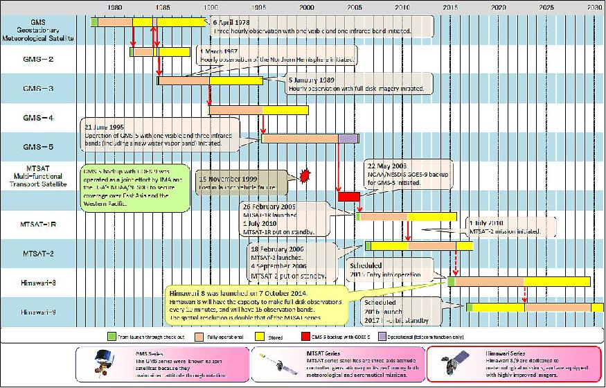
JMA (Japan Meteorological Agency) has operated the GMS (Geostationary Meteorological Satellite) and MTSAT (Multifunction Transport Satellite) series of satellites around the 140º east longitude to cover the East Asia and Western Pacific regions since 1978 and makes related contributions to the WMO's World Weather Watch (WWW) Program. As a follow-on to the MTSAT series, the Agency plans to operate next-generation satellites called Himawari-8 and Himawari-9 (Himawari means "sunflower" in Japanese). Unlike the current MTSAT series, which performs both meteorological and aeronautical functions, including air-traffic control communications and position information, Himawari-8 and -9 will have a dedicated meteorological mission. 1) 2) 3) 4) 5) 6)
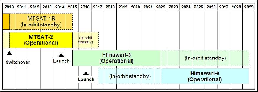
Currently (2014), MTSAT-2 (Himawari-7) is operational, while MTSAT-1R (Himawari-6) is on standby in orbit. MTSAT-2, which took over the Earth observation mission of MTSAT-1R on July 1, 2010, is scheduled to complete its observation operation around 2015. In order to provide continuous observation services, JMA plans to commence its operation in 2015, when MTSAT-2 is scheduled to complete its period of operation. The Agency also plans to launch Himawari-9 in 2016.
Spacecraft
In July 2009, JMA completed contract arrangements with MELCO (Mitsubishi Electric Corporation) for the manufacture of Himawari-8 and -9, which have identical specifications.
Spacecraft parameters: 8) 9) 10)
• The Himawari spacecraft is 3-axis stabilized with momentum bias. It features a MELCO DS-2000 bus. The overall size of the deployed spacecraft is 5.2 m (X-axis), 8.0 m (Y-axis), and 5.3 m (Z-axis).
• The launch mass is ~3500 kg, and the dry mass is 1300 kg.
• The design life is 8 years (including In-Orbit-Test) for AHI, and 15 years for the spacecraft bus.
• ADCS (Attitude Determination and Control Subsystem)
- Attitude sensors: Coarse Sun Sensor, Star Tracker, IRU (Inertial Reference Unit), Gyroscope
- Actuation device: RWA (Reaction Wheel Assembly)
• EPS (Electrical Power Subsystem): The power generated is 2.6 kW, the bus voltage is 100 V, use of a Li-ion battery.
• MDHS (Mission Data Handling Subsystem): MDHS connects with the AHI instrument using SpaceWire I/F and processes the data from the instrument into telemetry, based on the CCSDS recommendations. The processed data are sent to the Ka-band transmission system. MDHS also connects with a satellite control system by SpaceWire and sends commands to AHI.
• RF communications:
- Ku-band for TT&C services. The uplink rate is 500 bit/s, the downlink data rate is 15.36 kbit/s with a modulation PCM-PSK/PM
- Ka-band for payload data transmission. The data rate is 66 Mbit/s for AHI and 100 bit/s/300 bit/s for DCS. The modulation is QPSK, PCM-PSK, and no encryption.
- UHF for DCS: The data rate is 100 bit/s/300 bit/s with modulation of PCM-PSK.
For AHI data, compression is performed according to CCSDS Recommendation for Space Data System Standards. Lossless Data Compression, CCSDS 121.0-B-1 Lossless, May 1997.
Development Status
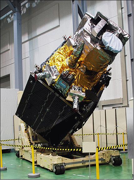
• On August 21, 2014, MELCO announced that it has completed work on the Himawari-8 satellite, the next-generation geostationary meteorological satellite, based on a contract awarded by the JMA(Japan Meteorological Agency). Himawari-8 was delivered soon to Tanegashima Space Center, Japan, from where it was launched. 11)
• In December 2013, ITT Exelis delivered the AHI instrument to Mitsubishi Electric Corporation. 12)
Launch
The Himawari-8 spacecraft was launched on October 7, 2014 (05:16:00 UTC) on an H-IIA vehicle (H-IIA F25) from the TNSC (Tanegashima Space Center) of JAXA, Japan. The launch service provider was Mitsubishi Heavy Industries, Ltd. The launch vehicle flew as planned, and, at about 27 minutes and 57 seconds after liftoff, the separation of the Himawari-8 was confirmed. 13) 14) 15)
Orbit: Geostationary orbit of Himawari-8 and Himawari-9, altitude of ~35,800 km, the longitude of ~140.7º east, covering the East Asia and Western Pacific regions, succeeding the GMS and MTSAT series.
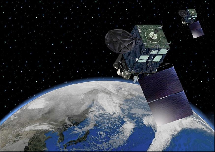
Note: Himawari-8 and Himawari-9 orbit in close formation, both at around 140.7°E (in line with Japan, Papua and central Australia). This will offer the same view when operations are switched between the satellites.
Launch: The Himawari-9 spacecraft of JAXA was launched on November 02, 2016 (6:20:00 UTC) on the H-IIA F31 vehicle of MHI (Mitsubishi Heavy Industries) from the TNSC (Tanegashima Space Center), Japan. The launch vehicle flew as planned, and at approximately 27 minutes and 51 seconds after liftoff, the separation of Himawari-9 was confirmed. 16)
Data Distribution / Dissemination plan for Himawari-8/9 17) 18)
Both Himawari-8 and -9 spacecraft do not carry any equipment for direct data broadcasting. Hence, JMA is discussing the utilization of ICS (Internet Cloud Service) and CTS (Commercial Telecommunication Satellite) as data distribution services (Figure 6). JMA will substitute the CTS broadcasting for current MTSAT direct broadcasting.
On the other hand, the Internet Cloud Service will be newly introduced as a means of data distribution for the National Meteorological and Hydrological Services (NMHSs) and for EUMETSAT. The agency will also introduce an Archive Server that is operated by the Japanese Science Group. Users of this server will be able to obtain all types of imagery from this server. Table 9 shows the receivable imagery products via the Internet Cloud Service / the CTS broadcasting. However, the types of imagery are limited for CTS broadcasting.
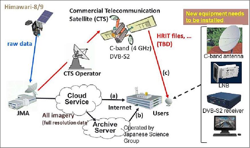
Table 1 shows the dataset disseminated via the HimawariCast service.
Himawari imagery in full-disk HRIT/LRIT files compatible with current MTSAT HRIT/LRIT data* is provided via the service. Files will be disseminated every 10 minutes in principle, but this interval will follow the MTSAT-2 observation schedule while MTSAT-2 is in operation. The number of bands of MTSAT-2 HRIT files is 5 out of 5, and that of Himawari-8 HRIT files is 14 out of 16.
In addition, numerical weather prediction (NWP) products GPVs (Grid Point Values) and meteorological observation data other than Himawari imagery in SATAID format are disseminated. Satellite Animation and Interactive Diagnosis (SATAID) visualization software for satellite imagery enable the superimposition of various meteorological data and products, such as NWP, in-situ observation data and ASCAT output, onto satellite imagery.
Data type | Format | Notes |
Himawari imagery | HRIT files | - Interval: 10 minutes(MTSAT-2 observation schedule followed while MTSAT-2 is in operation) |
LRIT files | - Interval: 10 minutes (MTSAT-2 observation schedule followed while MTSAT-2 is in operation) | |
Numerical weather | SATAID format | - JMA Global Spectral Model (GSM) products (48-hour forecast) |
In-situ observations | SATAID format | - Observational data for East Asia and Western Pacific regions |
ASCAT ocean surface wind | SATAID format | - Observational data from EUMETSAT's Metop polar-orbiting satellites |
Operation plan | Text | - Frequency: twice a day |
* There is a slight difference between files disseminated via the MTSAT HRIT/LRIT services and those disseminated via the HimawariCast service. The former consists of lossless-compressed raw data and related headers. The latter are made up of non-compressed raw data and related headers, and the whole files are compressed using bzip2. See the links for details (HRIT, LRIT). | ||
The specification list of receivers for CTS broadcasting is shown in Table 2. To receive imagery, the specification of equipment is needed. Note that the equipment for the current MTSAT direct broadcasting is not available for the CTS broadcasting.
Receiver configuration | Required/recommended specifications | Estimated cost (US$) |
C-band antenna | Dish type with a diameter of 1.2 – 2.4 m | 1,500 – 9,000 |
Low-noise block (LNB) | Standard-performance type | 600 or less |
DVB-S2 receiver [Digital Video Broadcasting – Satellite – Second Generation (a digital video broadcast standard)] | Standard-performance types such as Novra S300, Comtech EF DATA CMR-5975 or Advantech S4020 | 1,500 – 3,000 |
Software for DVB acquisition and processing | KenCast Fazzt standard software | 900 or less |
Mission Status
• January 14, 2020: In January 2020, the Taal Volcano awoke from 43 years of quiet and spewed lava and ash, filling streets and skies of the Philippine island of Luzon with fine ash fall and volcanic gases. The eruption caused tens of thousands of people to evacuate their homes and forced the closure of several key roads, businesses, and an airport. 19)
- The volcano first unleashed a steam-driven explosion (known as a phreatic eruption) on January 12. In the early morning of January 13, eruptive activity increased and the volcano emitted a fountain of lava for about an hour and a half. According to the Philippine Seismic Network, 144 volcanic earthquakes have been recorded since January 12, suggesting continuous magmatic activity underneath Taal and potentially more eruptive activity.
- According to news reports, the eruption of Taal lofted ash up to 14 km (9 miles) into the air. The eruption was accompanied by intense thunder and lightning above the summit. Winds carried volcanic ash north across Luzon.
![Figure 8: This map shows stratospheric sulfur dioxide concentrations on January 13, 2020, as detected by the Ozone Mapping Profiler Suite (OMPS) on the NOAA-NASA Suomi-NPP satellite [image credit: NASA Earth Observatory, image by Lauren Dauphin, using OMPS data from the Goddard Earth Sciences Data and Information Services Center (GES DISC). Story by Kasha Patel]](/api/cms/documents/163813/5228353/Himawari89_Auto16.jpeg)
- Taal is the second-most active volcano near Manila, which is located approximately 60 kilometres (40 miles) north of the volcano. In total, ten cities and municipalities surround Taal. The Philippine Institute of Volcanology and Seismology (PHIVOLCS) has ordered a "total evacuation" for people in high-risk areas within a 14-kilometre radius from the main crater, affecting around half a million people.
• December 11, 2019: Satellite remote sensing has widely been used to monitor and characterize the spatial and temporal changes of the Earth's vegetative cover. Satellites used in these analyses have conventionally been polar-orbiting satellites, which orbit from "pole to pole" and obtain only one to two images of the Earth per day. The utility of these polar-orbiting satellites has, however, often been limited because frequently occurring clouds block their view of the land surface. 20)
- New-generation geostationary satellites present an opportunity to observe land surfaces in a more efficient manner. Being in geostationary orbit, the Advanced Himawari Imager (AHI) sensor onboard Himawari-8, for example, can obtain multi-band colour images over Japan every 10 minutes, increasing the chance of obtaining "cloud-free" observations.
- In a new study published in Scientific Reports, an international team of researchers, including Tomoaki Miura from the University of Hawaii, Shin Nagai and Mika Takeuchi from Japan Agency for Marine-Earth Science and Technology, Kazuhito Ichii from Chiba University, and Hiroki Yoshioka from Aichi Prefectural University, examined this possibility and the utility of Himawari-8 AHI geostationary satellite data for capturing seasonal vegetation changes in Central Japan. 21)
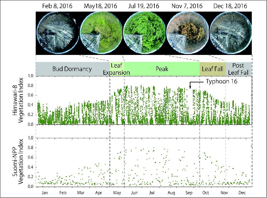
- Their study found that Himawari-8 AHI acquired approximately 26 times more observations than the Suomi-National Polar-orbiting Partnership (Suomi- NPP) Visible Infrared Imaging Radiometer Suite (VIIRS), one of the latest polar-orbiting satellite sensors, for the year 2016.
- As a result, there were a larger number of days with "cloud-free" observations with Himawari-8 AHI than with Suomi-NPP VIIRS. The study has demonstrated that the AHI geostationary sensor obtained one cloud-free observation data every 4 days, whereas the VIIRS polar-orbiting sensor was able to obtain one cloud-free observation every 7 to 16 days.
- Owing to this larger number of cloud-free observations, the AHI "vegetation index," a satellite measure of vegetation greenness, captured the temporal changes of vegetation from leaf expansion to leaf fall continuously throughout the growing season, corresponding to the observed vegetation phenology within situ time-lapse digital images (Figure 9). There were, however, several periods where even AHI was unable to obtain cloud-free observations due to persistent cloud cover during summer-fall seasons.
- "Detailed vegetation seasonal information from the Himawari-8 geostationary satellite can be useful for many applications such as short- term drought monitoring and assessing the impact of heavy rainfall events," said Prof Miura, the lead author of the study. "This study has shown that the Himawari-8 meteorological satellite can be used to monitor land surface and vegetation."
- "With new-generation geostationary satellites, we may begin to see various types of vegetation changes that could not be seen with previous satellites. The new findings contribute to understanding land-atmosphere carbon dioxide budgets," said Prof Ichii of Chiba University, a co-author of this study.
- The Himawari-8 AHI geostationary satellite also acquires multi-band colour images over the tropical Southeast Asia region every 10 minutes. It is expected that AHI geostationary sensor data would contribute to improving our understanding of vegetation dynamics and the effect of climate change in this cloud-prone tropical region.
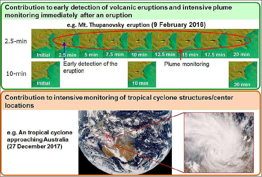
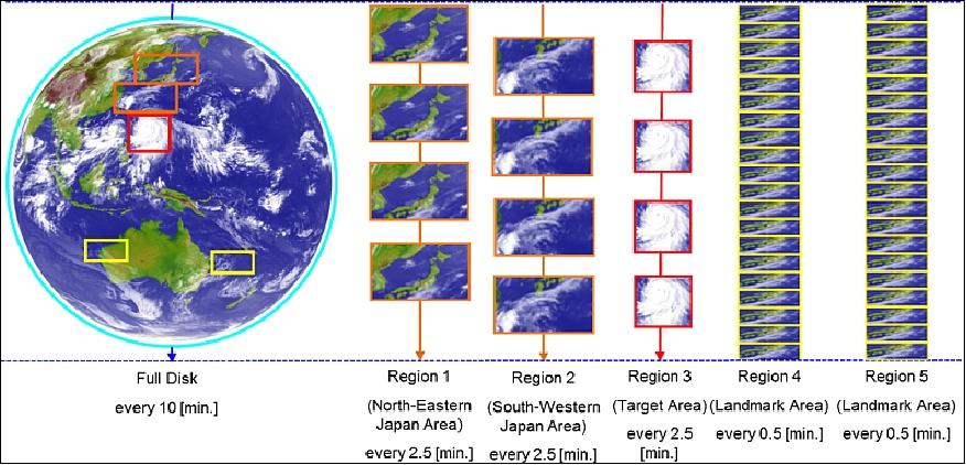
• January 18, 2018: JMA has launched its new international HimawariRequest service, which allows National Meteorological and Hydrological Services (NMHSs) to request Target Area observation conducted by Himawari-8/9 every 2.5 minutes. 22) 23)
- JMA's latest-generation Himawari-8 geostationary meteorological satellite began operation in July 2015, with the corresponding Himawari-9 unit entering a state of backup operation in March 2017. This dual satellite system is expected to provide a continuous stream of observation data for the Asia-Oceania region until 2029.
- AHI (Advanced Himawari Imager) on board Himawari-8/9 is capable of frequent and flexible observation, providing Full-Disk images of the Earth every 10 minutes and regional images with shorter intervals. Full-Disk and other regional observations have spatial resolutions of 0.5 to 2 km and spectral coverage incorporating 16 bands.
- In regional monitoring, Target Area observation provides imagery covering a 1,000 x 1,000 km area every 2.5 minutes with flexibility for location changes to support JMA's national and international services. The observation is normally focused on an area of active volcanoes in the domain of the Tokyo VAAC (Volcanic Ash Advisory Center), and is adapted to encompass typhoons within the responsibility area of the RSMC (Regional Specialized Meteorological Center) Tokyo Typhoon Center.
- The HimawariRequest service enables registered NMHS users to request particular Target Area observations in order to leverage this flexibility on an international scale. The service stems from a WMO RA II (Asia) regional project to develop support for NMHSs in satellite data, products and training in collaboration with WMO RA V (South-West Pacific) Members.
- JMA expects the HimawariRequest service to support disaster risk reduction activities in the region based on the monitoring of extreme events such as tropical cyclones and volcanic eruptions.
- Figure 26 shows the Target Area in the AHI observation sequence within a 10-minute time frame.
Using the power of Japan's K computer, scientists from the RIKEN AICS (Advanced Institute for Computational Science) and collaborators have shown that incorporating satellite data at frequent intervals—ten minutes in the case of this study—into weather prediction models can significantly improve the rainfall predictions of the models and allow more precise predictions of the rapid development of a typhoon. Weather prediction models attempt to predict future weather by running simulations based on current conditions taken from various sources of data. However, the inherently complex nature of the systems, coupled with the lack of precision and timeliness of the data, makes it difficult to conduct accurate predictions, especially with weather systems such as sudden precipitation. As a means to improve models, scientists are using powerful supercomputers to run simulations based on more frequently updated and accurate data. The team led by Takemasa Miyoshi of AICS decided to work with data from Himawari-8, a geostationary satellite that began operating in 2015. Its instruments can scan the entire area it covers every ten minutes in both visible and infrared light, at a resolution of up to 500 meters, and the data is provided to meteorological agencies. Infrared measurements are useful for indirectly gauging rainfall, as they make it possible to see where clouds are located and at what altitude. For one study, they looked at the behaviour of Typhoon Soudelor (known in the Philippines as Hanna), a category 5 storm that wreaked damage in the Pacific region in late July and early August 2015. In a second study, they investigated the use of improved data on predictions of heavy rainfall that occurred in the Kanto region of Japan in September 2015. These articles were published in Monthly Weather Review and Journal of Geophysical Research: Atmospheres. For the study on Typhoon Soudelor, the researchers adopted a recently developed weather model called SCALE-LETKF—running an ensemble of 50 simulations—and incorporated infrared measurements from the satellite every ten minutes, comparing the performance of the model against the actual data from the 2015 tropical storm. They found that compared to models not using the assimilated data, the new simulation more accurately forecast the rapid development of the storm. They tried assimilating data at a slower speed, updating the model every 30 minutes rather than ten minutes, and the model did not perform as well, indicating that the frequency of the assimilation is an important element of the improvement. To perform the research on disastrous precipitation, the group examined data from heavy rainfall that occurred in the Kanto region in 2015. Compared to models without data assimilation from the Himawari-8 satellite, the simulations more accurately predicted the heavy, concentrated rain that took place, and came closer to predicting the situation where an overflowing river led to severe flooding. According to Miyoshi, "It is gratifying to see that supercomputers along with new satellite data, will allow us to create simulations that will be better at predicting sudden precipitation and other dangerous weather phenomena, which cause enormous damage and may become more frequent due to climate change. We plan to apply this new method to other weather events to make sure that the results are truly robust." |
• On 24 January 2017, the first images from all 16 bands were captured by JMA's Himawari-9 geostationary meteorological satellite, which was launched on 2 November 2016. Testing and checking of the Himawari-9 system, including related ground facilities, are going well. Himawari-9 is scheduled to start operation in March 2017. 25)
• December 14, 2016: Himawari-8 Water Vapor (6.2 µm) images revealed the presence of a subtle packet of upper-tropospheric gravity waves propagating southeastward near the International Date Line (180º longitude over the central Pacific Ocean), just to the west/southwest of Midway Atoll on 14 December 2016 — and there were a few pilot reports of moderate to severe turbulence (which were responsible for at least one injury) in the general vicinity of this gravity wave feature from 1530 to 1740 UTC, at altitudes of 35,000 to 38,000 feet. 26)

• On November 11, 2016, the Himawari-9 satellite entered its geostationary orbit. 27)
• November 8, 2016: After in-orbit testing, Himawari-9 will stand by until 2022 as backup for the currently operational Himawari-8 geostationary satellite. HimawariCast users will not need to modify receiving system settings to continue data service usage even after the start of Himawari-9's operation. The combination of these two new-generation geostationary satellites will allow JMA to provide stable ongoing observation of the Asia and Pacific regions until 2029. 28)
• March 2016: According to JMA, the Himawari-8 spacecraft and its payload are operating nominally. 29)
• January 2016: The GSMaP (Global Satellite Mapping of Precipitation) product is a global rainfall map that is highly accurate, highly frequent, and high-spatial-resolution through the development of rain rate retrieval algorithms based on reliable precipitation physical models by using a number of microwave radiometer (imagers, sounders, and imager/sounders) observation data, and comprehensive use of the Precipitation Radar (PR) on board the TRMM (Tropical Rainfall Measuring Mission) satellite. To produce a highly frequent global rainfall map, sampling errors caused by unobserved regions by LEO (Low Earth Orbit) satellites are a problem. The GSMaP project has developed a method to interpolate observations between each microwave imager by utilizing information from the Infrared imagers on board the five geostationary satellites, which are JMA's MTSAT/Himawari satellite, two NOAA's GOES satellites, and EUMETSAT's Meteosat satellites, and achieved production of an hourly global rainfall map in 0.1º latitude/longitude grid. 30)
- JAXA has provided the near-real-time GSMaP (GSMaP_NRT) product four hours after observation through the "JAXA Global Rainfall Watch" website (http://sharaku.eorc.jaxa.jp/GSMaP/) since 2008 as a prototype of the GPM (Global Precipitation Measurement) mission.
• January 2016: ABI (Advanced Baseline Imager) class instruments of Harris Corporation are supporting three missions (Ref. 42):
- GOES-R (ABI) of NOAA, USA; Himawari: AHI (Advanced Himawari Imager) of JMA, Japan; and GEO-KOMPSAT-2A: AMI (Advanced Meteorological Imager) of KMA, Korea.
Four flight models were delivered:
- ABI PFM: Integrated on GOES-R spacecraft
- AHI-8: Operating on orbit (Himawari-8)
- ABI FM2: Delivered
- AHI-9: Integrated on Himawari-9 spacecraft.
Three more in production at Harris
- ABI FM3, ABI FM4, AMI.
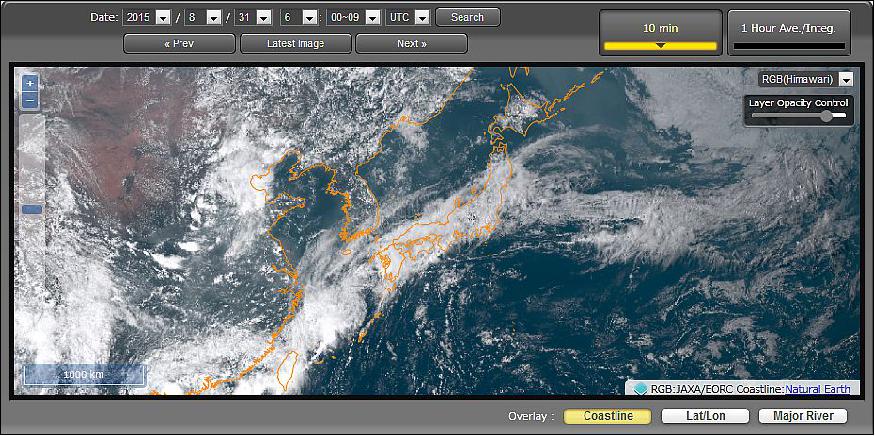
• Sept. 2, 2015: JAXA/EORC (Earth Observation Research Center) has released a new webpage, "JAXA Himawari Monitor" 31), showing the colour images and the quicklook images of the geophysical data from Himawari-8. 32)
- JAXA and JMA have exchanged agreements on the distribution and the release of meteorological data. Under this agreement, EORC has released the data from Himawari-8 to research communities and has been creating geophysical data that are consistent with JAXA's Earth observation satellites in order to release them widely to the general public. Other than releasing the images in the JAXA Himawari Monitor, EORC also stated to distribute via FTP the Himawari Standard Data and the geophysical data produced by JAXA.
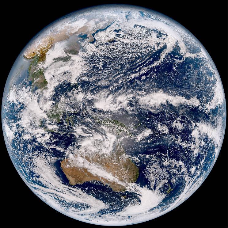
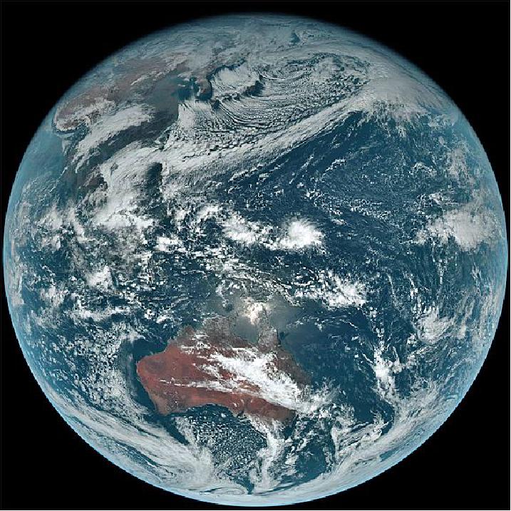
- The Himawari Standard Data includes the visible to infrared radiances (Band 1 to 16) for three regions of Full Disk (global), Japan Area and Target Area. The observation data can be achieved every 10 minutes for Full Disk and every 2.5 minutes for Japan Area and Target Area. Using the observation bands that enable the world's first "color image" from a geostationary satellite, one of the advanced aspects of Himawari-8, the JAXA Himawari Monitor shows the visible RGB composite images (Figure 13).
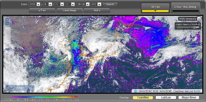
- In addition, for the Himawari geophysical data, JAXA/EORC produces the properties of atmospheric particles (called aerosols), such as desert dust and PM2.5 and the sea surface temperature. Both applied the algorithm developed for the JAXA's Earth observation satellites, including the GCOM-C ( Global Change Observation Mission – Climate) satellite, in order to produce, in the future, datasets that are consistent between the satellites and can compensate for each other's observations.
The aerosol property product (Figure 14) is being produced every 10 minutes in the daytime with a spatial resolution of 5 km. The current product is a beta version and will increase the quality through ground validation.
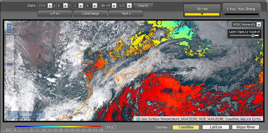
- There are two kinds of SST (Sea Surface Temperature) products: an ordinary product and a nighttime product.
The ordinary SST product (Figure 15) is a dataset produced every 10 minutes, regardless of day or night, with a spatial resolution of 2 km. In order to reduce the missing area by clouds, hourly averaged products are also created. The nighttime SST product uses Band 7 (3.9 µm wavelength) and, although it can only be retrieved at nighttime, its advantage is in its high accuracy. The dataset of the nighttime SST is an hourly averaged product with a spatial resolution of 2 km.
• July 7, 2015: The Himawari-8 geostationary meteorological satellite, managed by JMA (Japan Meteorological Agency), began its operational phase at 02:00 UTC on 7 July 2015, replacing the previous MTSAT-2 operational satellite (now on standby). 33)
- During the commissioning phase, Himawari-8's capacity for superior Earth monitoring with multi-band, high-resolution and high-frequency observation was verified. JMA firmly believes that Himawari-8 will open the door to a new generation of satellite meteorology and that it will contribute to the prevention and mitigation of weather-related disasters in the East Asia and Western Pacific regions as past satellites have done.
• July 1, 2015: JMA started Himawari-8 imagery dissemination via the HimawariCast service at 02:00 UTC on 1 July 2015, prior to Himawari-8 officially entering operation on 7 July. 34)
• In early 2015, Himawari-8 is testing and checking all systems in orbit and is scheduled to start operation in mid-2015. 35)
• On December 18, 2014, the first images from all 16 bands of the AHI (Advanced Himawari Imager) were captured by JMA's Himawari-8 next-generation geostationary meteorological satellite. 36)
• Himawari-8, entered the geostationary orbit on October 16, 2014 as planned. The satellite is expected to start operation in mid-2015 after the completion of in-orbit testing and checking of the overall system including related ground facilities. 37)
Sensor Complement
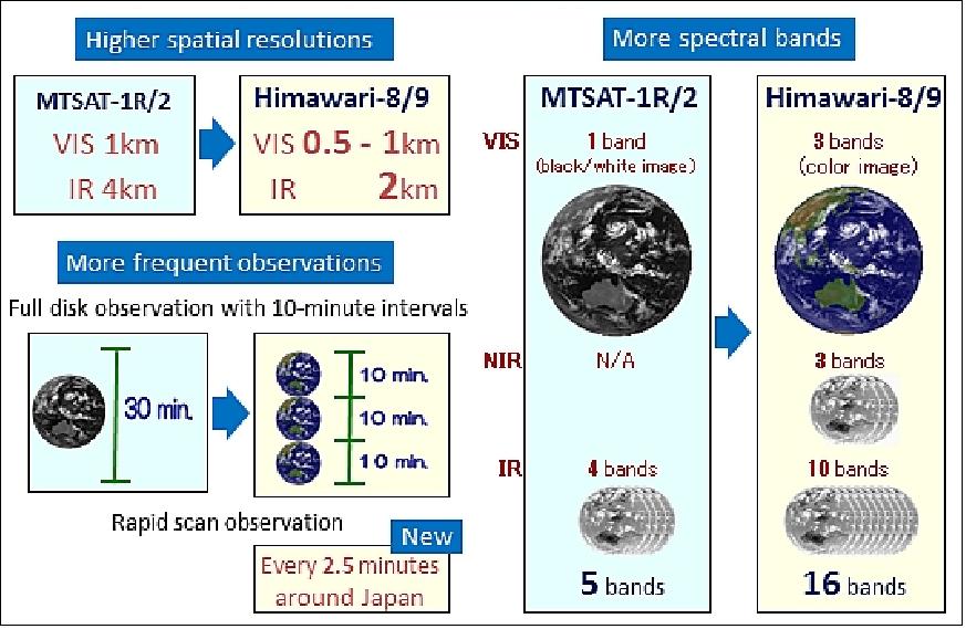
The functions and specifications of the Himawari-8 and -9 sensor complement are notably improved from those of the onboard imager of MTSAT. The Himawari-8 and -9 spacecraft carry the AHI (Advanced Himawari Imager) instrument to enable enhanced nowcasting, NWP (Numerical Weather Prediction) and environment monitoring. 39) 40)
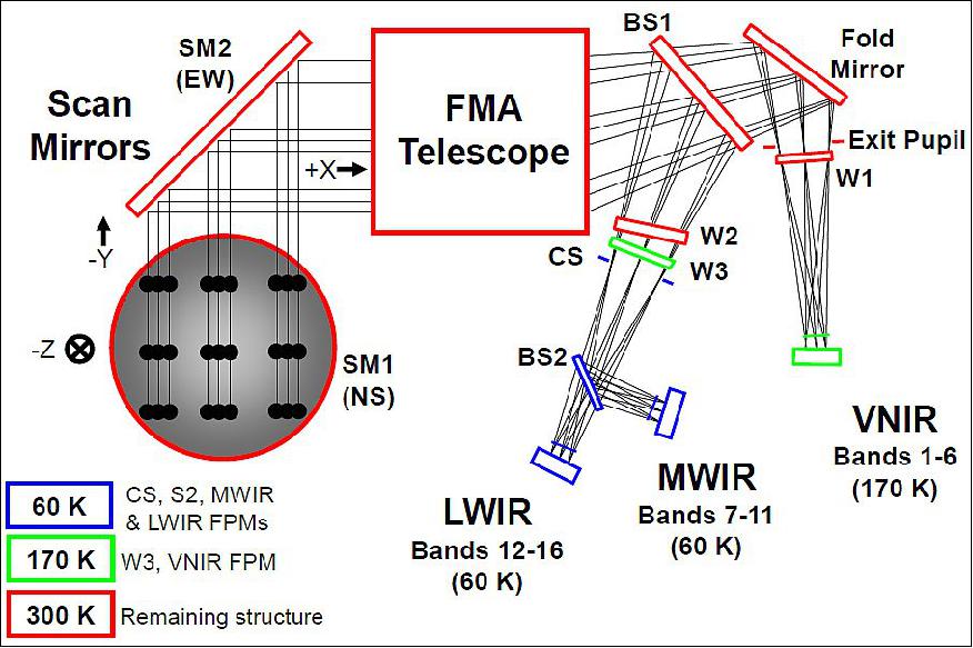
AHI (Advanced Himawari Imager)
AHI is an ABI (Advanced Baseline Imager) class instrument, designed and developed at Exelis Inc. of Rochester, N.Y., and similar to the one that will be integrated into the GOES-R spacecraft series of NASA/NOAA.
- Note: In May 2015, Harris Corp. of Melbourne, FL. acquired Exelis Inc. of Fort Wayne, IN. 41) 42)
In November 2009, MELCO selected Exelis (former ITT Space Systems) of Rochester, N.Y. to build the imaging systems for two geostationary satellites, Himawari-8 and -9, of JMA. 43) 44)
ABI and AHI both have 16 spectral channels in the visible and infrared spectrum, which is a significant increase in the number of spectral channels in comparison to heritage instruments. The two instruments have similar spectral bands with two main differences: ABI includes a 1.38 µm channel (for cirrus cloud detection), while this channel is replaced with a 0.51 µm channel (green band – to produce colour composite imagery) on AHI (Ref.12).
The AHI instrument provides the following general characteristics:
• Multi-purpose imagery for weather watch, NWP utilization and environment monitoring; and wind derivation by tracking clouds and water vapour features
• 16 channels operating in the VIS, NIR, SWIR, MWIR and TIR spectral bands, i.e. from ~ 0.43 to ~13.4 µm.
• AHI is replacing JAMI flown on Himawari-6 (MTSAT-1R) and IMAGER on Himawari-7 (MTSAT- 2)
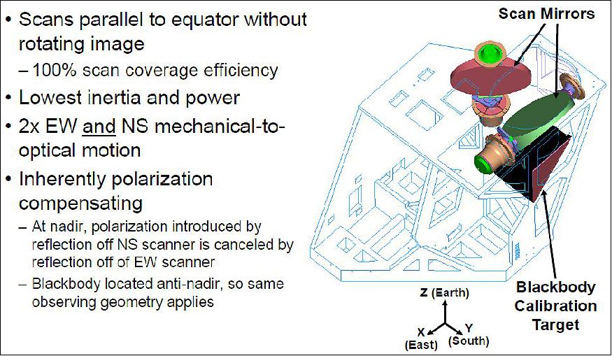
• Scanning technique: Mechanical, 3-axis stabilized satellite, E-W continuous, S-N stepping
• Spatial resolution: From 0.5 km to 2 km, depending on spectral band
• Coverage/cycle: Full disk in 10 minutes, limited areas in proportionally shorter intervals.
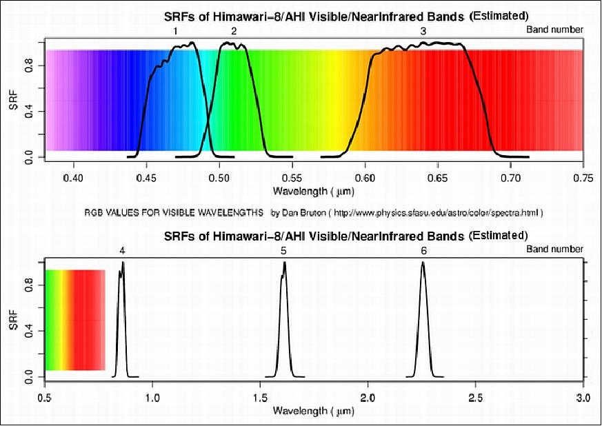
Band | Center | Bandwidth | SNR or NEΔT | Resolution at SSP | Prime measurement objectives and use of sample data |
1 | 470 nm | 50 nm | ≤ 300 @ 100 % albedo | 1.0 km | Daytime aerosol over land, coastal water mapping |
2 | 510 nm | 20 nm | ≤ 300 @ 100 % albedo | 1.0 km | Green band – to produce colour composite imagery |
3 | 644 nm | 30 nm | ≤ 300 @ 100 % albedo | 0.5 km | Daytime vegetation/burn scar and aerosols over water, winds |
4 | 860 nm | 20 nm | ≤ 300 @ 100 % albedo | 1.0 km | Daytime cirrus cloud |
5 | 1610 nm | 20 nm | ≤ 300 @ 100 % albedo | 2.0 km | Daytime cloud-top phase and particle size, snow |
6 | 2260 nm | 20 nm | ≤ 300 @ 100 % albedo | 2.0 km | Daytime land/cloud properties, particle size, vegetation, snow |
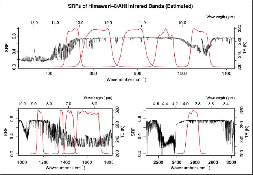
7 | 3.90 µm | 0.22 µm | ≤ 0.16 @ 300 K | 2.0 km | Surface and cloud, fog at night, fire, winds |
8 | 6.185 µm | 0.37 µm | ≤ 0.40 @ 240 K | 2.0 km | High-level atmospheric water vapor, winds, rainfall |
9 | 6.95 µm | 0.12 µm | ≤ 0.10 @ 300 K | 2.0 km | Mid-level atmospheric water vapor, winds, rainfall |
10 | 7.40 µm | 0.17 µm | ≤ 0.32 @ 240 K | 2.0 km | Lower-level water vapor, winds and SO2 |
11 | 8.50 µm | 0.32 µm | ≤ 0.10 @ 300 K | 2.0 km | Total water for stability, cloud phase, dust, SO2, rainfall |
12 | 9.61 µm | 0.18 µm | ≤ 0.10 @ 300 K | 2.0 km | Total ozone, turbulence, winds |
13 | 10.35 µm | 0.30 µm | ≤ 0.10 @ 300 K | 2.0 km | Surface and cloud |
14 | 11.20 µm | 0.20 µm | ≤ 0.10 @ 300 K | 2.0 km | Imagery, SST, clouds, rainfall |
15 | 12.30 µm | 0.30 µm | ≤ 0.10 @ 300 K | 2.0 km | Total water, ash, SST |
16 | 13.30 µm | 0.20 µm | ≤ 0.30 @ 300 K | 2.0 km | Air temperature, cloud heights and amounts |
FPM (Focal Plane Module) | FPA | Resolution (km) | AHI band No | Nominal Center Wavelength (µm) | ||
ABI | AHI | AMI | ||||
VNI | A047 | 1 | 1 | 0.47 | 0.47 | 0.47 |
A086 | 1 | 2 | 0.86 | 0.51 | 0.51 | |
A064 | 0.5 | 3 | 0.64 | 0.64 | 0.64 | |
A161 | 1 | 4 | 1.61 | 0.86 | 0.86 | |
A138 | 2 | 5 | 1.38 | 1.61 | 1.38 | |
A225 | 2 | 6 | 2.25 | 2.26 | 1.61 | |
MWIR | A390 | 2 | 7 | 3.9 | 3.9 | 3.9 |
A618 | 2 | 8 | 6.185 | 6.185 | 6.185 | |
A695 | 2 | 9 | 6.95 | 6.95 | 6.95 | |
A734 | 2 | 10 | 7.34 | 7.34 | 7.34 | |
A850 | 2 | 11 | 8.5 | 8.5 | 8.5 | |
LWIR | A961 | 2 | 12 | 9.61 | 9.61 | 9.61 |
A1035 | 2 | 13 | 10.31 | 10.35 | 10.35 | |
A1120 | 2 | 14 | 11.2 | 11.2 | 11.2 | |
A1230 | 2 | 15 | 12.3 | 12.3 | 12.3 | |
A1330 | 2 | 16 | 13.3 | 13.3 | 13.3 | |
|
| Color key: | Not in ABI | Different FPA | ||
• AHI & AMI added 1-km 0.51 µm channel (green)
- True 3-colour visible images
- Improved ocean images
• Retained 1-km 0.865 µm channel
- Shifted to HgCdTe detector array
• Changed 1.61 µm channel to 2 km
• Eliminated one NIR channel
- AHI: 1.378 µm
- AMI: 2.25 µm
Parameter | Unit | MI (Himawari-7) | AHI (Himawari-8) | Ratio |
Channels |
| 5 | 16 | 3.2 |
Detector elements: total |
| 24 | 77.400 | 3225 |
Detector elements: downlinked |
| 16 | 7,856 | 491 |
NS FOV: max channel | µrad | 274 | 16,311 | 60 |
EW FOV: max FPM | µrad | 140 | 33,203 | 237 |
AHI instrument calibration means:
• ICT (Internal Calibration Target) accurately calibrates emissive channels on-orbit
• SCA (Solar Calibration Assembly) delivers on-orbit calibration over mission life
• ECAL (Electronic Calibration) verifies linearity throughout the mission
• Operational calibration is routinely performed:
- Spacelook collected at least every 30 s (automatically collected as part of every Full Disk swath)
- Blackbody (ICT) observed at the start of each timeline
- Solar calibration scheduled when needed.
Onboard microvibration measures for AHI pointing error reduction:
One of the greatest obstacles to achieving high pointing accuracy is microvibration, which is induced by the dozens of disturbance sources inside the satellite; examples include reaction wheels, mechanical gyros, and coolers. In order to satisfy the requirement, an evaluation of the influence of microvibration before launch is necessary. 46)
In order for the AHI to achieve high-accuracy observations, the strict LOS (Line of Sight) pointing error is required. The LOS pointing error requirements for the AHI are shown in Table 7. The influence of the satellite bus system is considered in the requirements. Therefore, in order to satisfy the requirements for LOS pointing error, a high-accuracy attitude control system, technology for reducing the influence of microvibration, and a low thermal expansion optical bench, etc. are adopted.
Pointing error classification | Requirement (time) | Main cause | ||
LOS of | Attitude angle | Bias | - | - |
Drift | 14 µradp-p (600 s) | Alignment between IRU and optical bench, | ||
Jitter | 4 µrad 1σ (30/150/600 s) | Sensor Noise of IRU, ARS etc. | ||
Relative Pointing | Inner alignment of AHI | ±70 µradp-p (1day) | Inner alignment, Thermal deformation | |
error | 4 µradrms (30/150/600s) | Scan mirror encoder error | ||
Pointing jitter in the high-frequency region | Microvibration induced with RWA, IRU, Cooler | |||
In addition to the conventional attitude determination system for attitude control, the high accuracy and broadband attitude determination system of the optical bench is provided for correcting images for the ground system of the Himawari-8 and -9. The attitude determination system of the optical bench functions in combination with the data from the STT (Star Tracker), IRU (Inertial Reference Unit), ARS (Angular Rate Sensor), and ACC (Accelerometer) installed on the optical bench.
Some measures were taken to reduce the influence of microvibration induced with disturbance sources. Low-disturbance RWAs (Reaction Wheel Assemblies) are adopted, and an IRU (mechanical gyro), which generates the least level of disturbance, was selected. However, the LOS pointing error of a mission sensor is not only induced by disturbances generated from the disturbance sources discussed previously, but is also affected by the characteristics of the satellite structure. Therefore, in the early development phase of the Himawari-8, the disturbance analysis was conducted, using transfer functions calculated by finite element analysis, and the data of disturbance sources, and in the final development phase, the microvibration test was conducted using the protoflight model of the Himawari-8.
In summary, the motion of the optical bench, induced by disturbance sources installed in the Himawari-8, was evaluated with the data acquired in both the ground test and orbit. The results showed that the vibration level predicted from the ground test data almost exactly coincided with the data measured in orbit. The health of the onboard sensors was confirmed by comparing the ground test data with the in-orbit data. It was confirmed that the dominant disturbance sources in the Himawari-8 were the IRU and the cooler in the AHI. However, the microvibration level of Himawari-8 was still very quiet, compared to the ESA and JAXA satellite models.
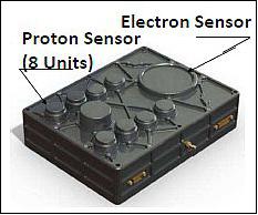
SEDA (Space Environment Data Acquisition Monitor)
SEDA will measure the radiation to which Himawari-8/-9 satellites are exposed in their geostationary Earth orbits. SEDA's design is basically identical to the EMU (Environmental Monitoring Unit) developed for the European satellite navigation system Galileo.
Parameter | Description |
Number of channels | Protons: 8 (individual 8 sensor elements) |
Energy range | Protons: 15 MeV – 100 MeV |
Time resolution | 10 s |
FOV (Field of View) | Protons: ± 39.35º |
DCS (Data Collection Subsystem)
The Himawari-8/-9 missions support the collection of surface-based observation data obtained by ground segments with corresponding onboard DCSs (Data Collection System) in the same manner as provided by the MTSAT series. DCP channels relay their data from the DCPs through a UHF transponder, which outputs the Ka-band signal.
Ground Segment
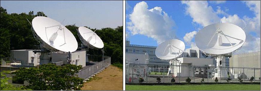
The Himawari-8 and -9 ground segment, designed, built and installed by MELCO, consists of antennas of 9 m diameter and radio frequency and satellite control equipment installed at the main unit in Hiki-gun, Saitama Prefecture, and the subunit in Ebetsu, Hokkaido. 47)
In August 2010, Himawari Operation Enterprise was established as a Special Purpose Company to operate the Himawari series spacecraft. This consortium is composed of Mitsubishi UFJ Lease & Finance Company Limited (representative company, management of office), NS Solutions Corporation (development of ground facilities, systems and maintenance work), and Space Engineering Development Co., Ltd. (service delivery), and has contracted this project with JMA in 2010 for the duration of 20 years until the end of March 2030 (4 years and 7 month development period, 15-year maintenance and service delivery period).
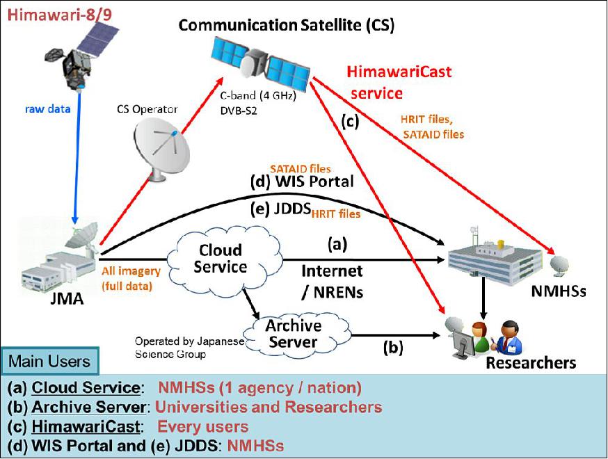
Legend to Figure 29: Himawari-8/9 will not carry equipment for direct dissemination. Instead, all imagery derived from the satellites will be distributed to NMHSs (National Meteorological and Hydrological Services) via an Internet cloud service (see (a) in Figure 29). Full sets of data will also be provided to researchers via archive servers operated by the Japanese Science Group on a best-effort basis (b). The HimawariCast service will additionally disseminate primary sets of imagery via a communication satellite using Digital Video Broadcasting — Satellite — Second Generation (DVB-S2) technology (c). Note: NREN (National Research and Education Network).
In addition, JMA will continue the current online imagery distribution service; WIS Portal (d) and the JDDS (JMA Data Dissemination System), (e) even after Himawari-8 takes over as the main operational satellite.
The HimawariCast Service
• MTSAT-2 imagery dissemination via the HimawariCast service began at 03:00 UTC on 29 January 2015. 49) 50) 51)
- MTSAT-2 imagery is currently provided directly via MTSAT-1R through the L-band frequency HRIT (High-Rate Information Transmission) and LRIT (Low-Rate Information Transmission) services. JMA will terminate these services in around November 2015. As a replacement for these services, JMA started the HimawariCast service which disseminates primary sets of imagery via a communication satellite from January 2015 onwards.
- The interval between full-disk observations by Himawari-8 will be 10 minutes, which is much shorter than the 30/60 minutes of the MTSAT series. The HimawariCast service will provide full-disk imagery with this high 10-minute observation frequency.
- JMA successfully launched Himawari-8 in October 2014 and will switch over operations from MTSAT-2 in mid-2015.
- The HimawariCast service is disseminating imagery of the current operational satellite, MTSAT-2, and Himawari-8 imagery will be disseminated after Himawari-8 becomes operational. JMA has the plan to disseminate Himawari-8 imagery on a trial basis while MTSAT-2 is in operation.
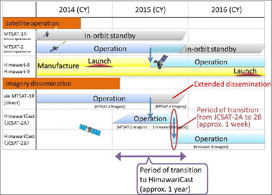
The JCSAT-2A communication satellite located at 154 ºE is used to broadcast data for the HimawariCast service. The JCSAT-2B unit will then take over from JCSAT-2A as the communication satellite in Q4 of 2015 at the same location. HimawariCast users will need to prepare for the transition from JCSAT-2A to JCSAT-2B during a dual operation period (approx. 1 week) of JCSAT-2A and JCSAT-2B.
The HimawariCloud Service
To distribute the enormous volumes of Himawari-8/9 imagery that will be produced, JMA will establish an Internet cloud service (HimawariCloud) mainly for NMHSs (National Meteorological and Hydrological Services) in the East Asia and Western Pacific regions.
Table 9 shows the tentative data set to be distributed via the cloud service. Himawari Standard Data will be used to create all products related to Himawari-8/9 as master data from all 16 bands with the finest spatial resolution. The true-colour images will be provided in Portable Network Graphics (PNG) format. For rapid scanning observation, imagery in Network Common Data Form (NetCDF) will also be created and distributed.
Format | Observation area | Description |
Himawari Standard Data | Full disk | - Interval: 10 minutes (full disk); 2.5 minutes (target area) |
Portable Network Graphics (PNG) | Full disk | - True-color images (composites of 3 visible bands) |
Network Common Data Form (NetCDF) | Target area | - Interval: 2.5 minutes |
Each NMHS will be able to access the cloud and get data using an HTTP 1.1 client such as a Web browser or Wget. It is important to note that an Internet connection with a speed of at least 25 Mbit/s will be required to download all Himawari Standard Data. These data will be separately created for each band and divided into 10 segments from north to south so that NMHSs can select only the files necessary for their operation.
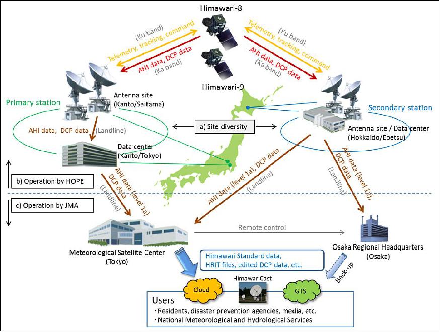
Overview of the Himawari-8/9 Ground Segment and Operations
The Himawari-8/9 satellites and their ground stations will be operated by Himawari Operation Enterprise Corporation (HOPE) — a special-purpose company (SPC) established under JMA's Private Finance Initiative (PFI) project. Observation data from the AHI (Advanced Himawari Imager) and DCP (Data Collection Platform) data will be transmitted through HOPE to JMA, which will process the information and disseminate products to users (Figure 31).
Site diversity:
Himawari-8/9 will use the Ka-band for AHI and DCP data downlink frequency, and will adopt the Ku-band for TT&C (Telemetry, Tracking and Command). To minimize the potential for negative data impacts from these bands, which both tend to be affected by rain attenuation, site diversity will be introduced by establishing two antenna sites (ASs). One will be in the Kanto region (the primary station) and the other will be in the Hokkaido region (the secondary station), meaning that their locations will be around 800 km apart and in different weather conditions. The two data centres (DCs) for processing the data received will also be located in the Kanto and Hokkaido regions.
Operation by HOPE:
HOPE will operate the ASs and DCs. The ASs will house transmitting/receiving equipment including antennas with a diameter of 9 m, and the DCs will have equipment for satellite control and AHI/DCP data processing. AHI and DCP data received at ASs will be transmitted to DCs, where the former will be processed to create level 1a data (raw data with calibration/navigation parameters attached) and the latter will be converted for use with JMA's telecommunications system. The processed data will be transmitted to JMA's Meteorological Satellite Center (Tokyo) and its Osaka Regional Headquarters (Osaka). In the event that the primary station becomes dysfunctional, the secondary station will take over its operations.
Operation by JMA:
The MSC (Meteorological Satellite Center) will receive data from both the primary and secondary stations for preprocessing, and Himawari Standard Data, HRIT files and edited DCP data will then be produced and provided to users. The Osaka Regional Headquarters will receive data from the secondary station only. In the event that the MSC system becomes dysfunctional (e.g., due to a malfunction caused by a natural disaster), data/products will be provided from Osaka.
References
1) http://www.jma-net.go.jp/msc/en/
2) Tatsuya Kimura, "Up‐to‐date Information on the Japanese Next‐Generation Himawari‐8/9 Satellites for Users' Preparedness," May 13, 2013, URL: https://web.archive.org/web/20151017013336/http://www.wmo.int/pages/prog/sat/meetings/documents/EC-65-SideEvent-UserPrep_Doc_02_JMA.pdf
3) Francis P. Padula, "Using S-NPP VIIRS as a Transfer Radiometer to Inter-compare GOES-R ABI and Himawari-8 AHI," https://ams.confex.com/ams/94Annual/webprogram/Paper235594.html
4) Yasushi Izumikawa, "Update of JMA's Status Report (2012)," Geneva, Switzerland, April 17-19, 2012, URL: https://web.archive.org/web/20170711111901/http://www.wmo.int/pages/prog/sat/meetings/documents/ET-SAT-7_Doc_05-05_JMA-update.pdf
5) Masaya Takahashi, "Status of Next Generation Japanese Geostationary Meteorological Satellites - Himawari-8/9 and their Products," NOAA Satellite Science Week: GOES-R AlgorithmWorking Group (AWG), Proving Ground, and Risk Reduction annual meetings, Kansas City,MO, USA, Apr. 30 - May 4, 2012, URL: http://www.goes-r.gov/downloads/2012-Science-Week/posters/tues/05_Takahashi.pdf
6) "JMA report on the status of current and future satellite systems," JMA, May 2014, URL: http://www.eumetsat.int/website/wcm/idc/idcplg?Id
cService=GET_FILE&RevisionSelectionMethod=LatestRe
leased&Rendition=Web&dDocName=CWPT_1186
7) Hiroshi Koide, "JMA Activities on New-generation Himawari-8 Geostationary Satellite in RA-V," 16th RA-V Tropical Cyclone Committee, Solomon Islands, 27 August 2016, URL: https://web.archive.org/web/20170629180323/http://www.wmo.int/pages/prog/www/tcp/documents/RAV_TCC-16_Item9.31_JMA_Koide.pdf
8) Information provided by Keiko Yamamoto of the Satellite Program Division, Japan Meteorological Agency (JMA).
9) "Himawari-8/9 Spacecraft Overview," JMA, URL: http://www.data.jma.go.jp/mscweb/en/himawari89/space_segment/spsg_spacecraft.html
10) "New geostationary meteorological satellites - Himawari-8/9," JMA Leaflet, URL: http://www.jma.go.jp/jma/jma-eng/satellite/materials/Himawari89/himawari89_leafret2/201507_leaflet89.pdf
11) "Mitsubishi Electric Ready to Deliver Himawari-8 to Tanegashima," MELCO, News Release No 2860, August 22, 2014, URL: http://www.mitsubishielectric.com/news/2014/0822.html
12) "Exelis delivers advanced weather satellite payload to commercial customer in Japan," Exelis, Dec. 18, 2013, URL: http://www.exelisinc.com/news/pressreleases/Pages/Exelis-delivers-advanced-
weather-satellite-payload-to-commercial-customer-in-Japan-.aspx
13) "Launch Success of H-IIA Launch Vehicle No. 25 with "Himawari-8" Onboard," JAXA Press Release, Oct. 7, 2014, URL: http://global.jaxa.jp/press/2014/10/20141007_h2af25.html#at
14) "Launch of H-IIA Launch Vehicle No. 25," JAXA Press Release, August 7, 2014, URL: http:/global.jaxa.jp/press/2014/08/20140807_h2af25.html
15) "Himawari-8 successfully launched," JMA, Oct. 7, 2014, URL: http://www.jma.go.jp/jma/jma-eng/satellite/news/himawari8
9/20141007_himawari-8_successfully_launched.pdf
16) "Launch success of the H-IIA Launch Vehicle No. 31 (H-IIA F31) with the geostationary meteorological satellite "Himawari-9" on board," JAXA Press Release, Nov. 2, 2016, URL: http://global.jaxa.jp/press/2016/11/20161102_h2af31.html
17) Hiroaki Tsuchiyama, Toshiyuki Kurino, Masaya Takahashi, "Progress on development of new products expected from Japanese follow-on geostationary meteorological satellites HIMAWARI-8/9," Proceedings of the Joint EUMETSAT /AMS Meteorological Satellite Conference to address issues on Weather, Climate, Oceans and the Environment, Vienna, Austria, Sept. 16-20, 2013, , URL: http://www.eumetsat.int/website/home/News/Conferencesand
Events/PreviousEvents/DAT_2027670.html
18) Kotaro Bessho, "Overview of Japanese new generation geostationary meteorological satellite, Himawari-8," The 1st KMA International Meteorological Satellite Conference, Seoul, Korea, November 16-18, 2015, URL: http://www.kmaimsc.kr/html/menu1_sub4.php
19) "Sulfur Spews from Taal," NASA Earth Observatory, Image of the Day for 14 January 2020, Instruments: Himawari-8, Suomi NPP — OMPS , URL: https://earthobservatory.nasa.gov/images/146142/sulfur-spews-from-taal
20) "Geostationary satellite an alternative to monitor land surfaces," Space Daily, 11 December 2019, URL: http://www.spacedaily.com/reports/Geostationary_satellite_an_alternative_to_monitor_land_surfaces_999.html
21) Tomoaki Miura, Shin Nagai, Mika Takeuchi, Kazuhito Ichii & Hiroki Yoshioka, "Improved Characterisation of Vegetation and Land Surface Seasonal Dynamics in Central Japan with Himawari-8 Hypertemporal Data," Scientific Reports, Vol. 9, Article number: 15692, Published: 30 October 2019, https://doi.org/10.1038/s41598-019-52076-x, URL: https://www.nature.com/articles/s41598-019-52076-x.pdf
22) "JMA Launches New International Service HimawariRequest Based on Himawari-8/9 Target Area Observation," JMA, 18 Jan. 2018, URL: http://www.jma.go.jp/jma/jma-eng/satellite/news/himawari89/20180118_HimawariRequest.pdf
23) "Himawari-8 data assimilated simulation enables 10-minute updates of rain and flood predictions," Riken Press Release, 18 Jan. 2018, URL: http://www.riken.jp/en/pr/press/2018/20180118_1/
24) RIKEN (Institute of Physical and Chemical Research, Tokyo, Japan) News, 18 January 2018, URL: http://www.riken.jp/en/pr/press/2018/20180118_1/
25) "First images from Himawari-9," JMA News Release, 24 Jan. 2017, URL: http://www.jma.go.jp/jma/jma-eng/satellite/news/himawari89/20170124_himawari9_first_images.html
26) "Moderate to severe turbulence aloft near the International Date Line," CIMSS Satellite Blog, Dec. 14, 2016, URL: http://cimss.ssec.wisc.edu/goes/blog/archives/category/himawari-8/page/2
27) "Himawari-9 enters geostationary orbit," JMA News Release, 11 Nov. 2016, URL: http://www.jma.go.jp/jma/jma-eng/satellite/news/himawari89/
20161111_himawari9_enters_geostationary_orbit.pdf
28) "HimawariCast Newsletter No. 2, 8 November 2016," JMA, URL: http://www.data.jma.go.jp/mscweb/en/himawari89/himawari_cast/
Newsletter/HimawariCast_Newsletter_02.pdf
29) "Himawari-8 Operational Schedule," JMA, April 1, 2016, URL: http://www.data.jma.go.jp/mscweb/en/operation8/bulletin_list_H8.html
30) Misako Kachi, T. Kubota, R. Oki, "Utilization of Himawari-8 in the Global Satellite Mapping of Precipitation (GSMaP) NowCast version," 12th Annual Symposium on New Generation Operational Environmental Satellite Systems, AMS Annual Meeting, 11-14 January 2016, New Orleans, Louisiana, USA, URL: https://ams.confex.com/ams/96Annual/webprogram/Paper285626.html
31) http://www.eorc.jaxa.jp/ptree/index.html
32) "Release of JAXA Himawari Monitor," JAXA, Sept. 2, 2015, URL: http://www.eorc.jaxa.jp/en/imgdata/topics/2015/tp150902.html
33) "Himawari-8 operation initiated," JMA News Release, July 7, 2015, URL: http://www.jma.go.jp/jma/jma-eng/satellite/news/himawari89/
20150707_himawari-8_operation_initiated.pdf
34) "Dissemination via communication satellite: the HimawariCast service," JMA/MSC (Meteorological Satellite Center), URL: http://www.data.jma.go.jp/mscweb/en/himawari89/himawari_cast/himawari_cast.html
35) Information provided by Kazuki Yasui of JMA, Tokyo, Japan.
36) "First images from Himawari-8," JMA, Dec. 18, 2014, URL: http://www.jma.go.jp/jma/jma-eng/satellite/news/himawari89/
20141218_himawari8_first_images.html
37) "Himawari-8 enters geostationary orbit," JMA News Release, Oct. 18, 2014, URL: http://www.jma.go.jp/jma/jma-eng/satellite/news/himawari89/
20141017_himawari-8_enters_geostationary_orbit.pdf
38) http://www.jma.go.jp/jma/jma-eng/satellite/introduction/20141007_chronologicaltable.pdf
39) http://www.data.jma.go.jp/mscweb/en/himawari89/index.html
40) "Himawari-8/9 and MTSAT-1R/2 imagery channels and file sizes," URL: http://www.jma.go.jp/jma/jma-eng/satellite/news/2013_Questionnaire/
Annex1_ImageryChannelsAndFileSizes.pdf
41) "Harris Corporation Completes Acquisition of Exelis," Press Release, May 29, 2015, URL: http://www.exelisinc.com/news/pressreleases/Pages
/Harris-Corporation-Completes-Acquisition-of-Exelis.aspx
42) Paul C. Griffith, "Advanced Himawari Imager (AHI) Design and Operational Flexibility," 12th Annual Symposium on New Generation Operational Environmental Satellite Systems, AMS Annual Meeting, 11-14 January 2016, New Orleans, Louisiana, USA, URL: https://ams.confex.com/ams/96Annual/webprogram/Handout/
Paper289069/NGOESS-7.1_Griffith_AHI_Design_v2.pdf
43) ITT picked to build the imaging systems for Japanese weather satellites," ITT, Nov. 2, 2009, URL: http://www.itt.com/News/Releases/2009/ITT-Picked-to-Build-Advanced-Imaging-Systems-for-J/
44) http://www.data.jma.go.jp/mscweb/en/himawari89/space_segment/spsg_ahi.html
45) Paul C. Griffith, "Advanced Himawari Imager (AHI) Design and Operational Flexibility," Sixth Asia/Oceania Meteorological Satellite Users' Conference, November 9 - 13, 2015, Tokyo/Japan, URL: http://www.data.jma.go.jp/mscweb/en/aomsuc6_data/oral/s02-01.pdf
46) Osamu Takahara, Takeya Shima, Hitoshi Kitamura, Norimasa Yoshida, "Prediction of the Microvibration from Ground Test and Its In-orbit Evaluation of the Geostationary Meteorological Satellite ‘Himawari-8'," Proceedings of the 67th IAC (International Astronautical Congress), Guadalajara, Mexico, Sept. 26-30, 2016, paper: IAC-16-C2.3.10
47) "Himawari Operation Enterprise and Mitsubishi Electric Complete Ground Facilities for Weather Satellite Operations," MELCO, October 7, 2013, URL: http://www.mitsubishielectric.com/news/2013/1007.pdf
48) http://www.data.jma.go.jp/mscweb/en/himawari89/
49) "Dissemination via communication satellite: the HimawariCast service," JMA, Feb. 2015, http://www.data.jma.go.jp/mscweb/en/himawari89/himawari_cast/himawari_cast.html
50) "HimawariCast: dataset, JMA, Jan. 29, 2015, URL: http://www.data.jma.go.jp/mscweb/en/himawari89/himawari
_cast/note/HimawariCast_dataset_en.pdf
51) "Distribution via Internet cloud service: the HimawariCloud service," JMA, URL: http://www.data.jma.go.jp/mscweb/en/himawari89/cloud_service/cloud_service.html
The information compiled and edited in this article was provided by Herbert J. Kramer from his documentation of: "Observation of the Earth and Its Environment: Survey of Missions and Sensors" (Springer Verlag) as well as many other sources after the publication of the 4th edition in 2002. - Comments and corrections to this article are always welcome for further updates (eoportal@symbios.space).
Spacecraft Launch Mission Status Sensor Complement Ground Segment References Back to Top