Meteosat First Generation
EO
ESA
Atmosphere
Ocean
Meteosat First Generation (MFG) was a series of seven meteorological satellites, operated by EUMETSAT (European Organisation for the Exploitation of Meteorological Satellites), beginning in November 1977 with the launch of Meteosat-1. MFG provided cost-effective satellite data and related services on a continuous basis, within the specific field of meteorology, and concluded in 2017 with the retirement of Meteosat-7.
Quick facts
Overview
| Mission type | EO |
| Agency | ESA, EUMETSAT |
| Mission status | Mission complete |
| Launch date | 23 Nov 1977 |
| End of life date | 11 Apr 2017 |
| Measurement domain | Atmosphere, Ocean |
| Measurement category | Cloud type, amount and cloud top temperature, Liquid water and precipitation rate, Surface temperature (ocean), Atmospheric Humidity Fields, Atmospheric Winds |
| Measurement detailed | Cloud top height, Cloud cover, Precipitation intensity at the surface (liquid or solid), Cloud imagery, Atmospheric specific humidity (column/profile), Sea surface temperature, Cloud top temperature, Wind profile (horizontal) |
| Instruments | MVIRI, Meteosat Comms |
| Instrument type | Imaging multi-spectral radiometers (vis/IR), Communications |
| CEOS EO Handbook | See Meteosat First Generation summary |
Summary
Mission Capabilities
MFG satellites carried three instruments, Meteosat Visible and Infrared Imager (MVIRI), a high resolution radiometer and the primary observation payload, Laser Synchronisation from Stationary Orbit (LASSO), a series of laser retro-reflectors included in the sensor complement from Meteosat-3 onwards, and Space Environment Monitor-2 (SEM-2) an electron spectrometer flown only on Meteosat-3. MVIRI provided simultaneous image generation in the thermal infrared region (TIR), in the water vapour absorption bands (WV), and in the visible range (VIS), with applications in atmospheric winds, atmospheric humidity fields, cloud type, amount and cloud top temperature, surface temperature (ocean), liquid water and precipitation rate. Meanwhile, LASSO aimed to demonstrate high accuracy time standard synchronisation over large distances, and SEM-2 aimed to investigate the link between deep dielectric charging and the spacecraft anomalies recorded on Meteosat-1 and -2.
Performance Specifications
MVIRI operated in three spectral regions, the thermal infrared region (TIR), water vapour absorption bands (WV), and in the visible range (VIS), with spectral ranges of 0.5 - 0.9 µm in for VIS, 5.7 - 7.1 µm in WV, and 10.5 - 12.5 µm in TIR. The instrument had a Field of View (FOV) of 18° and an IFOV (Instantaneous FOV) of 0.065 mrad in VIS, and 0.14 mrad in WV and TIR bands. MVIRI had spatial resolution at nadir of 2.5 km for VIS band, and 5 km in WV and TIR bands. LASSO was capable of time standard synchronisation to an accuracy of one nanosecond, and measuring the orbital distance of the satellite to an accuracy of within 0.1 m. SEM-2 had an energy range of 42.9 - 300 KeV, with data provided in two temporal resolutions, high at 500 - 600 second averages, and low at 30 minute averages.
The MFG series operates in a geostationary orbit, at an altitude of 35,786 km above the equator, with a nominal position at 0° longitude.
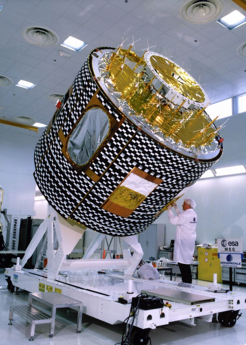
Space and Hardware Components
The Meteosat buses were built by Aerospatiale of Cannes (later Alcatel Space), France as prime contractor to ESA along with a consortium of European subcontractors. The buses consisted of a cylindrical body with a diameter of 2.10 m and an overall length of 3.195 m. The bus was spin-stabilised, with a dual-spin configuration at 100 rpm. It had a dry mass of 322 kg, with a launch mass of 696 kg and four 10 N thrusters for orbit injection, as well as two 2 N actuation thrusters. The bus design life was five years, and it housed the sensor payload, Radio Frequency (RF) communications systems, and the Meteosat Data Collection System (DCS), which facilitated an operational collection service for a large number of data collection platforms within its field of view (approximately 80°of arc of its subsatellite point). RF communications occurred in S-band for transmission of raw image data, TT&C (Tracking Telemetry and Control) and uplink of image dissemination data from the primary station to the spacecraft, and in L-band for High Resolution Image (HRI) digital image dissemination and meteorological data distribution.
Meteosat First Generation (MFG) Spacecraft
Overview Mission Status Spacecraft Sensor Complement References
Early history:
Meteosat is the European meteorological program in GEO (Geostationary Orbit) that was initiated in 1972 by ESRO (European Space Research Organization). ESRO was founded in 1962 and served as the predecessor organization to ESA (European Space Agency) which was founded in 1975. Actually, the beginnings of European space meteorology go back to 1968 when CNES, the young French national space agency, proposed to ESRO to "Europeanize" its "Meteosat" concept. The proposal was accepted in 1972 and 8 Member States decided to finance the Meteosat Preoperational Program (Belgium, Denmark, France, Italy, Germany, the United Kingdom, Sweden and Switzerland).
Meteosat-1 was the first European meteorological geosynchronous satellite, launched on November 23, 1977, almost 10 years prior to the existence of EUMETSAT (the European agency for meteorological satellite operational services - similar to NOAA, its counterpart in the USA). The overall objective of the Meteosat system was -and still is - the provision of cost-effective satellite data and related services on a continuous basis to support the requirements of the EUMETSAT Member States. The data and services are mainly focused on the requirements of operational meteorology, with an emphasis on support to operational weather forecasting - along with support for many other disciplines and applications. 1) 2)
In March 1983, an inter-governmental conference at ESA decided that the execution of an Operational Program of Meteosat would be entrusted to ESA, which would cover:
• The development and launching of three Meteosat Operational Program (MOP) spacecraft of an improved design compared with the preoperational satellites
• The construction of a complete set of spares
• The exploitation of the spacecraft observations (from the Preoperational to the Operational Program) from November 1983 until November 1995.
The success of the Meteosat preoperational program led a large group of European nations to establish firm plans for sustained operations by an independent agency. On May 24, 1983, 16 countries signed the EUMETSAT (European Organisation for the Exploitation of Meteorological Satellites) convention, which came into force in June 1986. On January 1, 1987, responsibility for the operation of the Meteosat satellites was transferred from ESA to EUMETSAT. EUMETSAT is the owner of the Meteosat series beginning with Meteosat-4.
Since then ESA continued to build the MOP (Meteosat Operational Program) spacecraft series as a EUMETSAT contractor. In a 1993 agreement, EUMETSAT was given the full operational mandate. This means that EUMETSAT provides all operational functions and services of its satellites (with a dedicated EUMETSAT ground segment) established in 1995. 3) 4) 5) 6)
On Nov. 15, 1995, EUMETSAT took over the operations of the Meteosat system and implemented the Meteosat Transition Program (MTP). This program included the provision and launch of a further satellite of the same design (Meteosat-7), the development of a new ground system, and routine operations from December 1995 onwards.
In 1994 EUMETSAT commenced two new programs:
1) MSG (Meteosat Second Generation), a geostationary program with a first launch in 2002 and operational services starting in 2004
2) EPS (EUMETSAT Polar System), a LEO (Low Earth Orbit) meteorological program with the MetOp services starting in the year 2005/6. The space segment of both of these programs is being developed in cooperation with ESA.
The Meteosat series itself is part of a global network of geostationary meteorological satellites distributed around the equator. All activities regarding satellites and operations are coordinated by the CGMS (Coordination of Geostationary Meteorological Satellites) committee represented by WMO and the countries providing the satellites: Europe (EUMETSAT), USA (NOAA), Russia (NPO Planeta), Japan (JMA), India (ISRO), China (CMA). - Meteosat geostationary satellites are nominally positioned at 0o longitude.
The general coverage region of the Meteosat satellites (at 0o location over the equator) is most of Europe, the whole of Africa, the Atlantic Ocean and the eastern half of South America, and the Middle East (Figure 1).
Meteosat launch services - Meteosat-1 was launched on November 23, 1977, by a Thor-Delta vehicle from Cape Canaveral, FLA, USA. All the following Meteosat satellites were launched on Ariane vehicles from Kourou, French Guinea.
Mission Status
• January 23, 2015: When Meteosat-7 was launched in September 1997, it was the seventh and last in the Meteosat First Generation series of satellites, but was the first solely controlled by EUMETSAT. It was launched under the MTP (Meteosat Transition Program) to prevent a gap in geostationary coverage, before the new generation of Meteosat satellites (Meteosat Second Generation). MTP was the first program to be initiated by EUMETSAT, instead of ESA, and prompted the decision to set up EUMETSAT's own ground segment. 7)
- The various facts and services of Meteosat-7 are listed in Table 1. On January 24, 2015, Meteosat-7 became the longest-serving operational satellite in EUMETSAT history, clocking up 17 years of monitoring the weather from space.
- In early 2015, Meteosat-7 is still providing coverage over the Indian Ocean, located above the equator at longitude 57.5 °E, at an altitude of 35,786 km. The satellite is generally in good health, having suffered only a few anomalies over the years.
- There is approx 6.38 kg of fuel available on board, and 3.9 kg is reserved for re-orbiting at the end of the satellite's life. It is expected that Meteosat-7 should be able to support IODC (Indian Ocean Data Coverage) until the end of 2016 or possibly 1st quarter of 2017.
Prototype satellites of the preoperational program series | ||
Spacecraft | Launch date | Comments |
Meteosat-1 | 23.11.1977 | Service provision until Nov. 1979 when the imager failed prematurely. |
Meteosat-2 | 10.06.1981 | Service operation from Aug. 12, 1981 until Aug. 11, 1988 as prime satellite. |
Meteosat-3 | 15.06.1988 | Meteosat P2 was a refurbished prototype of Meteosat-2 - initially designated as Meteosat-P2 (Engineering Prototype model). |
MOP (Meteosat Operational Program) Missions | ||
Meteosat-4 | 19.04.1989 | MOP-1: First image of MOP-1 on April 19, 1989 |
Meteosat-5 | 02.03.1991 | MOP-2: Meteosat-5 acted as primary S/C for the 0o service over Europe from Feb. 1994 until 1997. |
Meteosat-6 | 20.11.1993 | MOP-3: Meteosat-6 provided image data for Europe; the S/C was retired from its regular duties in Jan. 2007. |
Meteosat-7 | 03.09.1997 | MOP-4: Meteosat-7 was part of the MTP (Meteosat Transition Program) toward MSG (Meteosat Second Generation). |
Since 1991, EUMETSAT has been exploiting 2 Meteosat spacecraft:
1) The regular (primary) coverage of Europe is provided at 0o location over the equator.
2) At the end of its primary service period a Meteosat S/C is repositioned over the Indian Ocean ( at 63o E)- and used as backup as well as for IODC (Indian Ocean Data Coverage) services. In addition, these S/C are being used for the provision of data collection services of the Indian Ocean ground segment DCPs (Data Collection Platforms) in support of the Indian Ocean Tsunami Warning System. This service provision started with Meteosat-5.
Meteosat-3 was repositioned in 1991 to 50o (75o W in Feb. 1993) to fill a possible data gap for NOAA.
Spacecraft
Meteosat is a spin-stabilized spacecraft (dual-spin configuration at 100 rpm). It features a cylindrical body of 2.10 m in diameter, and the overall length is 3.195 m. The spacecraft is composed of a main cylindrical body, with a drum-shaped section of 1.3 m diameter and two concentric cylinders stacked on top. The main cylindrical body contains most of the S/C subsystems including the payload. Its outer surface is covered with six solar panels (more than 8000 cells) for power generation (200 W average). The surface of the drum-shaped section is covered with an array of radiating dipole antenna elements. Electronics within the drum activate the individual elements in the sequence, in reverse order to the S/C spin sense. The drum constitutes an electronically despun portion of the S/C, namely the antenna whose function is to ensure that S-band communications are always directed towards Earth.
Two Earth horizon sensors and two sun sensors provide attitude information. The S/C has four main thrusters (10 N) for orbit injection and two 2 N thrusters as actuators (hydrazine propellant) for orbit/attitude control. The S/C dry mass is 322 kg (plus 40 kg of hydrazine). The S/C launch mass is 696 kg. The design life is 5 years. 10)
The preoperational and MOP series satellites were built by Aerospatiale of Cannes (France) as the prime contractor to ESA (later Alcatel Space), along with a consortium of European subcontractors.
Spacecraft mass | 320 kg (dry mass), 696 kg (launch mass) |
Spacecraft diameter | 2.10 m |
Electrical power | 200 W |
Spacecraft stabilization | spin-stabilized (100 rpm) |
The cylindrical surface of the smaller drum-shaped section, mounted on top of the S/UHF platform (Figure 4), is covered with an array of radiating dipole antenna elements. Electronics within the drum activate the individual elements in the sequence, in reverse order to the satellite spin sense. This subsystem constitutes an electronically-despun antenna whose function is to ensure that the main transmissions in S-band are always directed towards the Earth. The two cylinders mounted on top of the drum are toroidal pattern antennas for S-band and low UHF respectively.
Meteosat RF Communications
• S-band in the frequency range of 2098 - 2110 MHz.
- Transmission of raw image data from the S/C to Fucino, Italy (primary ground station)
- TT&C data
- Transmission of DCP reports
- Uplink of image dissemination data from the primary station to the S/C
- Uplink of MDD (Meteorological Data Distribution) data from a ground station
• L-band in the frequency range of 1675-1696 MHz. The L-band is for user-related functions for the following services:
- WEFAX analogue image dissemination and DCP retransmissions (1691.0 MHz)
- HRI (High-Resolution Image) digital image dissemination, with a few WEFAX transmissions (1694.5 MHz)
- Meteorological data distribution with up to four channels spaced at 30 kHz (1695.605 - 1695.935 MHz)
• UHF-band in the frequency range of 402.0-402.2 MHz. DCPs (Data Collection Platforms) may be given access to one of the 66 uplink UHF channels at 3 kHz separation.
Application: Weather forecast, meteorology, climatology (sea surface temperature monitoring, cloud cover statistics, wind and rainfall assessment). Collection of environmental data.
Orbit - GEO (geostationary) with an orbital altitude of about 35,786 km above the equator, nominal position at 0o longitude.
Sensor Complement
MVIRI (Meteosat Visible and Infrared Imager)
The prime observation payload of the 1st generation Meteosat spacecraft, MVIRI, consists of a high-resolution 3-band radiometer, providing simultaneous image generation in the thermal infrared region (TIR), in the water vapour absorption bands (WV), and in the visible range (VIS).
Objectives/applications: Earth and atmospheric monitoring, operational meteorology, climatology. Basic climatological data sets and precipitation indices are derived daily. Measurements: day/night cloud coverage, cloud motion winds, cloud top heights, upper tropospheric humidity, precipitation and sea surface temperature. MVIRI spins with the S/C platform spin rate of 100 rpm. The MVIRI instrument was developed at Matra Marconi Space and was flown on all 1st generation spacecraft from Meteosat-1 to Meteosat-7. 11)
Parameter / Bands | VIS (Visible band) | WV (Water Vapor) absorption band | TIR (Thermal Infrared) window |
Telescope aperture | 400 mm (primary), 140 mm (secondary) | ||
Telescope focal length | 3,650 mm | 535 mm | |
|
|
|
|
Spectral range | 0.5 - 0.9 µm | 5.7 - 7.1 µm | 10.5 - 12.5 µm |
FOV (Field of View) | 18o (0.314 rad) | ||
IFOV (Instantaneous FOV) | 0.065 mrad | 0.14 mrad | 0.14 mrad |
Ground pixel size (nadir), spatial resolution | 2.5 km x 2.5 km | 5 km x 5 km | 5 km x 5 km |
Scan lines per image | 5000 (each line of 5000 pixels) | 2500 (each line of 2500 pixels) | 2500 (each line of 2500 pixels) |
Line duration | 30 ms | ||
Line recurrence | 600 ms | ||
Number of pixels/image | 25 Mpixel | 6.25 Mpixel | 6.25 Mpixel |
Image duration/recurrence | 25 min (scanning), 30 min (duty cycle = 100%), with 5 minutes spare time for a retrace of the scan mirror | ||
Detector type | Si | HgCdTe | HgCdTe |
Number of detectors | 2 (+2 redundant)) | 1 (+1 redundant) | 1 (+1 redundant) |
Radiometer performance | SNR > 200 for 25% albedo | NEDT < 1.0 K at 260 K | NEDT < 1.0 K at 260 K |
Data transmission rate | 333 kbit/s (normal), 2.7 Mbit/s (burst mode) | ||
Instrument mass | 63 kg (instrument height of 1.35 m) | ||
MVIRI is a passive imaging radiometer, the optical system consists of a scanning Ritchey-Chretien telescope with a primary aperture of 400 mm diameter (140 mm secondary aperture) and focal lengths of 3650 mm for VIS and 535 mm for WV and IR ranges. A series of mirrors is used to collect the incoming radiation and to focus it onto the corresponding detectors (silicon photodiodes for VIS, HgCdTe detectors for IR and WV). The HgCdTe detectors are cooled to 90 K by a passive system. The S/C scans the full Earth disk within a 30 min period (all bands). Scanning from east to west is achieved through the S/C spin. Scanning from south to north is achieved by small incremental steps in the pointing direction of the telescope. At each satellite rotation during the imaging process, the spin clock delivers a signal to the scanning motor electronics, which has the effect of rotating the telescope through an angle of 1.25 x 10⁻⁴ radians.
The water vapour (WV) channel was implemented experimentally on the first three satellites but was included operationally beginning with Meteosat-4. In fact, the Meteosat-1 spacecraft was the first geostationary orbit satellite with a water-vapour imaging capability.
At any given time, one infrared detector, one water vapour detector and one pair of visible detectors will be in operation. Since the detectors are distributed across the focal plane of the radiometer their respective fields of view on the earth scene do not coincide but are displaced relative to each other. The misalignment due to these displacements is corrected by central on-ground image processing before the images are distributed to users.
MVIRI calibration is provided by two black bodies located on opposite sides of the main optical path, one is kept at 290 K, and the other is kept at 340 K. In addition, cold space views are obtained during normal imaging operations.
LASSO (Laser Synchronization from Stationary Orbit)
This package of laser retro-reflectors was added to Meteosat-3. Objective: demonstration of the time standard synchronization over large distances with 10-9 s accuracy. The laser pulses could also measure the orbital distance of the spacecraft within 10 cm.
The LASSO payload consisted of: 12) 13) 14)
• Retroreflector array
• Detection unit
• Time-tagging unit
• Ultra-stable oscillator.
The LASSO experiment was designed for comparing the time at two or more laser-ranging sites. LASSO was onboard MeteoSat-3 (P2) and validated the concept of optical time transfer. The experiment also demonstrated the interest and potential of this high-precision method of time transfer. The first time transfer experiments between two stations in Europe (Grasse France and Graz Austria) were conducted in 1988. Trans-Atlantic time transfers were realized between the Grasse France and McDonald TX USA laser stations with a precision better than 100 ps and an accuracy of 1.5 ns in 1992.
SEM-2 (Space Environment Monitor-2)
SEM-2 was flown on Meteosat-3 only. SEM-2, an electron spectrometer, was provided by LANL (Los Alamos National Laboratory) to investigate the link between deep dielectric charging and the spacecraft anomalies seen on Meteosat-1 and -2. The instrument's energy range observes both trapped radiation belt electrons and freshly injected electrons when substorms occur. The energy range of the detector is 42.9-300 keV, which is divided into five differential energy ranges by discriminators. Data is available at high time resolution (500 s, 500 s, 600 s averages) and low time resolution (30-minute averages).
The electronics and the calibration of the instrument were provided by MSSL (Mullard Space Science Laboratory) of UCL (University College London). The instrument contained five surface barrier detector-collimator systems, oriented at polar angles of 30o, 60o, 90o, 120o, and 150o relative to the spacecraft spin vector, which was approximately parallel to the Earth's spin axis. Each collimator covered a nominal 10o full angle. Each system measured electrons in 5 energy channels between 43 and 300 keV. In 100 seconds, full energy and azimuthal coverage were obtained, for a particular polar angle. In 5 successive 100-second intervals, the full latitudinal coverage was also obtained. A Memory Upset Monitor was also included, looking for single-event upset errors in a known memory pattern in the memory of a test RAM.
Meteosat Data Collection System (DCS)
The Meteosat DCS provides an operational collection service for a large number of data collection platforms within its field of view (about 80o great circles of the arc of its subsatellite point).
The overall system is composed of the following subsystems: 15) 16)
1) The space segment: a DCS platform on Meteosat satellites consisting of: a UHF/S-band transponder, an electronically despun S-band antenna, a UHF receive antenna and, as a backup, an S-band toroidal pattern transmit antenna.
2) The Data Collection Platforms (DCPs) in the ground segment
3) The Meteosat ground station (ESA Odenwald station) and DCP processor at ESOC Darmstadt
The DCS onboard Meteosat provides a transponder with a pass band that is divided into 66 communication channels (3 kHz per channel). A message from a DCP in the ground segment is relayed via the DCS to the Meteosat ground station. Each DCP is allocated one of the 66 parallel channels. Since the DCP transmit either according to a schedule or under `alert' conditions, many platforms can use a single 3 kHz channel sequentially. The platforms (DCPs) transmit (uplink) their data in the 402 MHz UHF band to the Meteosat DCS, where it is converted to S-band (1675 MHz) and retransmitted (downlinked) to the Meteosat ground station. There, the signals received are checked for quality before being transmitted to ESOC for processing and distribution. At ESOC, all DCP messages are collected, processed, disseminated in near real-time and distributed to the platform owners. The distribution of DCP data can also be achieved via the `DCP Retransmission' service.
Data Collection Platforms
Meteosat services about 1000 DCPs in the ground segment. The coordinated DCS design approach from Meteosat (Eumetsat), GOES (NOAA) and GMS (JMA) allows the reports from DCP carried on ships, aircraft and other mobile platforms, moving from one satellite coverage area to another, to be received and transmitted by one of the satellites in the network (and transmitted via terrestrial lines throughout the world).
Meteosat services three basic types of DCPs (Eumetsat requires certification and licensing of all DCPs):
• `Self-timed' DCPs, which transmit their data at regular intervals based on an internal clock (this is the most common type of platform in use)
• `Alert' DCPs, which transmit a small amount of data when a particular parameter has been exceeded. The transmission time of `alert' DCP messages is limited to about 10 seconds in order to decrease the probability of overlapping messages on the same channel.
• `Hybrid' DCPs, which are a combination of `alert' and `self-timed' DCPs.
DCP transmissions are limited to about 1 minute, each transmission is termed a DCP message. One DCP message may contain several sets of information or `reports.'
A message format consists of the following contiguous elements:
• unmodulated carrier for 5 seconds
• a 250-bit preamble (alternating `0' and `1' - to acquire the bit rate and lock onto it)
• a 15-bit synchronization word
• the DCP address (a 31-bit Bose-Chaudhuri-Hocquenghem (BCH) coded word)
• the data field (up to 5192 bits, - `alert' DCPs are limited to 184 bits of data)
• the 31-bit End of Transmission (EOT) sequence.
The DCP RF uplink is in the UHF band (between 402.001 and 402.199 MHz). The Meteosat DCS transponder permits up to 33 international [in common with GOES and GMS spacecraft (402.0025 - 402.0985 MHz)] and 33 regional channels (402.1015 - 402.1975 MHz) for DCP reports. The carrier is phase modulated by the signal bit stream, the modulation index being 60o.
`Self-timed' DCPs report according to a schedule agreed to by the DCP owner and the operations center. Depending on the application this may range from several times per hour to once every 24 hours. Each hour is divided into 40 timeslots; each report must be completed within its given time slot. Since the maximum duration of a report is about one minute, at least 30 seconds are available as a guard time to accommodate any drift in the DCPs internal clock.
`Alert' DCPs transmit on channels which are free of self-timed DCPs. Although the duration of an alert message is limited to about 10 seconds, it is of course possible that two or more alert reports will overlap on the same frequency channel. The event of such an overlap entails the loss of both messages. In order to reduce this overlap probability, alert platforms repeat their messages several times at fixed time intervals.
DCS Access Method.
Data transmission from a DCP to the Meteosat DCS is generally self-triggered by the DCP. All DCS receivers are in listening mode trying to lock onto any message that is being assigned to them by the DCPs on a random access basis. The mean availability of the DCS is >95%, a user can expect that more than 95% of the messages transmitted by his DCP are being received, processed and distributed.
DCP Data Processing.
The data handling system performs the following functions (starting in 1995):
• Completeness checks for constituting blocks and DCP address recognition
• Storing of DCP messages and processing information onto a database
• Monitoring of reporting DCPs with respect to a predefined schedule (check of transmission chain)
• A log of received and processed messages, including anomalies
• Processing of DCP data and bulletin preparation for distribution
• Archiving of DCP data. Retrieval for DCP users
• Generation/storage of performance analysis.
All geostationary meteorological satellites series (Meteosat, NOAA-GOES, GMS (JMA), etc. use DCS (or variations thereof. Note: the ARGOS-DCS concept on polar-orbiting NOAA-POES S/C with the corresponding PTTs (ground) differs in uplink frequency, message length and format).
Meteosat DCP Retransmission System
DCP users may also directly receive their (DCP and/or WEFAX) data if a Secondary Data User Station (SDUS) is operated on their home premises. This service is offered to users at any point within the Meteosat telecommunication range. DCP data received at the Meteosat ground station are preprocessed and routed to ESOC. Those DCP data intended for direct retransmission are selected and routed to a special processing unit in the ground station. The selection is made by using look-up tables of DCP addresses. All DCP data listed in these look-up tables are buffered and transmitted in a time-sharing mode over one of the Meteosat transponder channels used for image transmission (1691, 1694.5 MHz). DCP data is transmitted in time slots between image transmissions. The time slot is 27 seconds between two WEFAX transmissions. DCP data transmission may be continuous if there is no transmission of WEFAX images or ranging. The bit rate during transmission is 12.5 kbit/s; on average, there are 15 transmission slots of 27 seconds per hour. 17)
WEFAX (Weather Facsimile) transmissions are in a format compatible with the APT (Automatic Picture Transmission) service of the NOAA-GOES and POES series.
The WEFAX transmission format consists of the following elements: 18) 19)
• Start signal (300 Hz), 3 seconds
• Phasing signal, 5 seconds
• Image (800 lines), 200 seconds
• Stop signal (450 Hz), 5 seconds
Consecutive WEFAX transmissions are scheduled in 4-minute slots. This leaves a break of 27 seconds between two WEFAX transmissions. In these 27-second intervals, the stored DCP reports are disseminated, the individual reports being packed into HDLC frames.
MOSAIC
All weather services rely heavily on the timely distribution of meteorological observations and derived products. These requirements have stimulated the development of a meteorological data distribution service. The principal Meteosat missions can be combined by the user to provide an integrated data access system. This concept is known as `Meteosat Operational Systems for data Acquisition and InterChange' (MOSAIC). Since 1991 users can readily combine satellite imagery, local reports from the data collection system, as well as conventional meteorological data and forecasts. Meteosat acts in this setup simply as a relay for most data distribution services (direct broadcast). The MDD (Meteorological Data Dissemination) system is one facet of MOSAIC; it provides a service with enormous distribution potential, particularly across Africa and the Middle East.20)
MDD (operational since 1992) consists of three elements: the uplink sites, the Meteosat transponder (relay), and the user reception stations. The initial two operational uplink sites are at Bracknell (UK Meteorological Office) and at Rome (Italian Meteorological Service). A third uplink started operations in 1994 (Toulouse, France). The data sets disseminated via MDD channels consist of meteorological information in the form of alphanumeric characters, bit-oriented data streams, and graphical information - all of which use a common data transmission protocol.
MDD offers four downlink channels from Meteosat in S-band (1695 MHz), each with a transmission rate of 2400 bit/s. The channel spacing is 31.2 kHz with a bandwidth of ±10 kHz for each channel.
The following center frequencies are either in use or reserved for future extension:
• Channel 1: 1695.6938 MHz
• Channel 2: 1695.7250 MHz (Bracknell, UK)
• Channel 3: 1695.7562 MHz (Toulouse, France)
• Channel 4: 1695.7874 MHz (Rome, Italy)
MDD transmission from the source to the receiving stations is as follows:
• The GTS (Global Telecommunication System of WMO) is used for the acquisition by the MDD uplink station (see Figure 9)
• The link protocol in the ground segment is X.25 (CCITT)
• The data blocks are received by the MDD uplink preprocessor (encryption and FEC)
• The data are uplinked via Meteosat relay function to the receiving stations
• Each MDD receiving station acquires the data blocks, preprocesses them and reassembles the data into WMO bulletins or meteorological charts.
Application:
an extensive range of operational meteorological charts covering Africa, the Middle East, Europe, Asia, parts of the Americas, and all intervening oceans is broadcast through the MDD service from Bracknell.
References
1) R. Tessier, "The Meteosat Programme," ESA Bulletin 58, May 1989, pp. 45-57
2) "Meteosat First Generation (MFG) geostationary satellites have provided images of the full Earth disc, and data for weather forecasts for 25 years," EUMETSAT, URL: http://www.eumetsat.int/website/home/Satellites/PastSatellites/index.html
3) John Morgan, "Current and Planned European Operational Meteorological Satellite Systems," Proceedings of the Twenty-Third International Symposium on Remote Sensing of The Environment, Bangkok, Thailand, April 18-25, 1990, ERIM, Ann Arbor, MI, Vol. I, pp. 107-116.
4) `The Meteosat Operational Programme - From Experiments to Exploitation,' Earth Observation Quarterly, No. 25, March 1989
5) Introduction to the METEOSAT Operational System, ESA BR-32 ISSN 250-1589, Sept. 1987
6) `EUMETSAT Directory of Meteorological Satellite Application,' ISBN 92 91110 006 4, 1991, EUMETSAT
7) "On 24 January 2015, Meteosat-7 becomes the longest-serving operational satellite in EUMETSAT history, clocking up 17 years of monitoring the weather from space," EUMETSAT, Jan. 23, 2015, URL: http://www.eumetsat.int/website/home/News/DAT_2526201.html
8) METEOSAT Image Newsletter, Issue 32, May 2010, pp.. 6 & 8, URL: http://www.eumetsat.int/Home/Main/AboutEUMETSAT/Publications
/IMAGENewsletter/groups/cps/documents/document/pdf_image32_en.pdf
9) M. Schick, "GSCB Workshop 2012 EUMETSAT Missions," 3rd GSCB (Ground Segment Coordination Body) Workshop, 2012, ESA/ESRIN, Frascati, Italy, June 6-7, 2012, URL: http://earth.esa.int/gscb/papers/2012/17-EUMETSAT_missions.pdf
10) "The METEOSAT System, EUM TD 05, December 1998, brochure provided by EUMETSAT, URL: http://medhycos.mpl.ird.fr/en/data/tec/dcp/Meteosat/TD05-part1.pdf
11) Meteosat, URL: http://sci.esa.int/science-e/www/object/doc.cfm?fobjectid=36459
12) B. Serene, "The LASSO experiment on the Meteosat-P2 spacecraft," ESA Bulletin No 49, Feb. 1987, pp. 20-23
13) P. Fridelance, C. Veillet, "Operation and data analysis in the LASSO experiment," Metrologica, Vol. 32, 1995, pp. 27-33
14) C.. Veillet, P. Fridelance, D. Feraudy, Y. Boudon, P. J. Shelus, R. L. Ricklefs, J. R. Wiant, "LASSO observations at McDonald (Texas, USA) and OCAfCERGA (Grasse, France)," 1992
15) "Meteosat Data Collection System," March 1990, ESOC
16) "Data Collection System," URL: http://medhycos.mpl.ird.fr/en/data/tec/dcp/Meteosat/TD05-part3.pdf
17) "Meteosat DCP Satellite Retransmission System," January 1990, ESOC
18) "Meteosat WEFAX Transmissions," ESOC paper, March 1990
19) "Meteosat High Resolution Image Dissemination," ESOC paper, Oct. 1989
20) "MOSAIC Meteorological Data Distribution," EUMETSAT, EUM UG 01
The information compiled and edited in this article was provided by Herbert J. Kramer from his documentation of: "Observation of the Earth and Its Environment: Survey of Missions and Sensors" (Springer Verlag) as well as many other sources after the publication of the 4th edition in 2002. - Comments and corrections to this article are always welcome for further updates (eoportal@symbios.space).
Overview Mission Status Spacecraft References Back to top