Neutron-1 CubeSat
Non-EO
Quick facts
Overview
| Mission type | Non-EO |
| Launch date | 02 Oct 2020 |
| End of life date | 25 Jun 2022 |
Neutron-1 (CubeSat mission to study neutron flux in LEO)
Spacecraft Launch Payload Ground Station References
The Neutron-1 mission is a 3U CubeSat being developed by the Hawaii Space Flight Laboratory (HSFL) at the University of Hawaii at Manoa (UHM). The satellite will study low energy neutron flux in Low Earth Orbit (LEO) as a function of time and location. The science payload, a small neutron detector developed by Arizona State University (ASU) for the LunaH-Map, will focus on measurements of low energy secondary neutrons, one of the components of the LEO neutron environment. In addition, this mission presents an excellent opportunity to establish flight heritage and demonstrate the technological capabilities of the NASA EPSCoR (Established Program to Stimulate Competitive Research) funded COSMOS (Comprehensive Open-architecture Solution for Mission Operations Systems). COSMOS is an open source set of tools that is being developed at HSFL as an integrated operations solution (including flight software, ground station operations, and mission operations center) for Small Satellite missions. It is intended to enable/facilitate SmallSat mission operations at universities with limited budgets and short schedules. 1)
Overview
Neutrons in LEO have three major sources: production in the atmosphere via Galactic Cosmic Radiation (GCR) and Earth's radiation belt, production in the spacecraft by the same ionizing radiation interacting with spacecraft materials, and direct emission from the Sun during large Solar Particle Events (SPE). These neutrons are slowed by components of the atmosphere. One fraction is absorbed by nuclear reactions, another fraction decays, and the significant remainder leaves the atmosphere forming the Earth albedo neutron flux. The flux and energy spectrum of these neutrons are variable in time and space, as their production depends on variable high-energy charged particle fluxes and properties of the upper atmosphere.
The overall science goal of the Neutron-1 mission is to measure the time dynamics of low energy Earth albedo neutrons as a function of solar activity level, time, and space coordinates of the CubeSat. To achieve this goal, we use the small neutron detector developed by ASU for the upcoming LunaH-Map mission. 2) 3) 4) The measurements will focus on low energy secondary neutrons, one of the components of the LEO neutron environment. Maps of secondary low energy neutron abundances will be derived from the data as a function of latitude, longitude, and time.
Data gathered by the neutron detectors will contribute to understanding the complex relationship between the Earth and the Sun through mapping neutron abundances in LEO. We will also evaluate our neutron data for potential application in space weather characterization and radiation safety.
The LunaH-Map mission is seeking to make neutron observations around the Moon to evaluate the abundance of water ice on the lunar surface. Neutron-1 will provide the LunaH-Map instrument on-orbit flight experience. The experiment will evaluate detector sensitivity, particle count accuracy, data processing capability, Single Event Upset (SEU) effects, and in-space operability in an environment similar to lunar orbit; moreover, Neutron-1 will allow ASU to evaluate instrument spaceflight performance and gain flight heritage. The performance information collected will allow ASU to make required improvements to the LunaH-Map instrument prior to its lunar mission. Flight heritage is important for the LunaH-Map mission to ensure instrumentation is tested and reliable prior to flight. The Neutron-1 launch date aligns with the ASU requirements and facilitates ample time to make adjustments and modifications to the instrument before the LunaH-Map launch.
Spacecraft
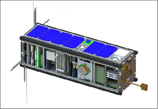
The Neutron-1 mission is a 3U CubeSat being developed by the Hawaii Space Flight Laboratory (HSFL) at the University of Hawaii at Manoa (UHM). A rendering of the Neutron-1 CubeSat is shown in Figure 1. The satellite will study low energy neutron flux in Low Earth Orbit (LEO) as a function of time and location. The spacecraft bus was integrated and tested at HSFL. The science payload, developed by Arizona State University (ASU), uses a novel elpasolite sensor, 5) developed for the Lunar Polar Hydrogen Mapper, or LunaH-Map Mission (Ref. 2).
Neutron-1 is designed to the 3U CubeSat standard, the NASA CubeSat Launch Initiative (CSLI) Launch Services Program (LSP) requirements, and the NanoRacks CubeSat Deployer (NRCSD) requirements. Besides the program level, launch, and deployment requirements, the main mission requirements were as follows:
1) The CubeSat shall be 3-axis stabilized and be capable of orienting the instrument aperture in four different directions: the flight direction, opposite to the flight direction, nadir and zenith. The Science mission requires that data will be taken for 10 orbits in each direction.
2) The ADCS (Attitude Determination and Control Subsystem) shall provide a pointing accuracy of ± 5° or better for the science mode and the antenna pointing.
3) The OBC (On-Board Computer) shall store and forward the instrument data to the ground and include a redundant data channel.
4) The instrument requires ~1MB of data per orbit, this includes science data volume and state of health data. Each science data collection orbit the instrument is on during 7.5 minutes.
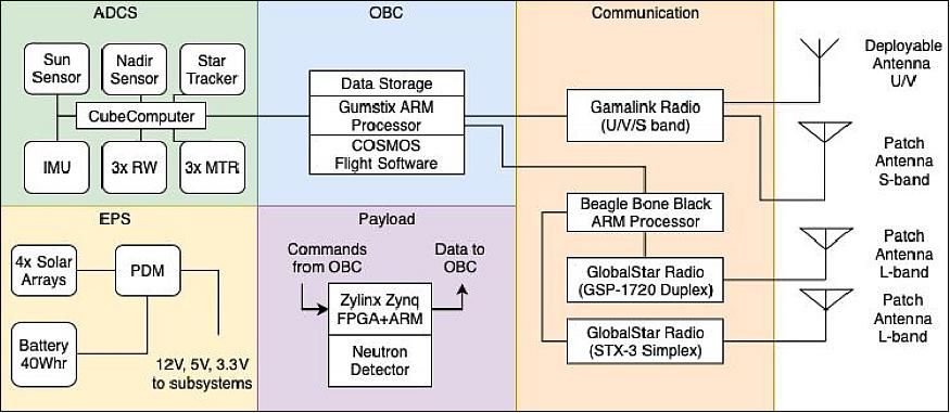
Spacecraft architecture: To support the science instrument the Neutron-1 bus system includes the primary OBC that serves to control the instrument data collection and to store and forward the data to the ground. The EPS (Electrical Power System) provides switchable power to the various systems in the bus and it is charged with four body mounted solar panels. The ADCS provides the 3-axis system stabilization to perform science experiments. Finally the RF Communication system uses three different radios to transfer information. The science data is transferred via an S-band channel while the command and control of the spacecraft is executed via the globalstar radio. Figure 4 shows the overall system diagram.
Spacecraft bus: Several off-the-shelf structures were evaluated for use as the primary structure for Neutron-1. A principal evaluation criterion in selecting a structure from Clyde Space ÅAC was the compatibility of the structure with predetermined flight hardware such as the CubeADCS. Several modifications were made to the structure to accommodate the various bus and payload components as they matured. The shear panels were also customized.
Most subsystems utilize the CubeSat Kit (CSK) form factor with the exception of the instrument payload and GlobalStar communications package. To accommodate these components, custom brackets and mounts were designed and fabricated. FEA analysis was performed in these cases to levels compliant with the NanoRacks CubeSat Deployer Interface Definition Document. Acceptable factors of safety were greater than 1.25 for tensile yield strength and greater than 1.4 with respect to ultimate tensile strength.
ADCS (Attitude Determination and Control Subsystem): The ADCS used for this mission is a CubeADCS 3-Axis integrated bundle from CubeSpace (Figure 3). Attitude determination is conducted via sensor measurements from ten coarse sun sensor diodes, two CMOS cameras as fine sun and Earth sensors, three MEMS gyro rate sensors, a three-axis magnetometer, and a low-power star tracker. These sensor measurements are combined using an extended Kalman filter, and used with control algorithms for 3-Axis pointing (including Earth target tracking, Sun tracking, inertial pointing etc.). The CubeADCS enables full 3-Axis control of the satellite utilizing three reaction wheels, and three magnetorquers used for desaturation of the built up momentum in the wheels. Fine Point mode is entered when the following requirements are met: valid attitude is obtained by star tracker and propagated by the IMU, a valid time is obtained by GPS and propagated by onboard oscillator and the GPS has acquired a valid ephemeris. The ADCS uses the 3-axis reaction wheel setup with the maximum momentum of 1.77 mNms and a maximum torque of 0.23 mNm.
EPS (Electrical Power Subsystem): The Neutron-1 bus electrical power system receives power input from the HSFL solar panels. The average power generated in nominal mode is ~5 W. The average power consumption is 4.5 W over the 90 min orbit. The solar power is stored in a 40 Whr lithium polymer battery pack and distributed via an EPS unit, both made by ClydeSpace. The 40 Whr battery consists of two lithium polymer pouch cells in a 2s4p arrangement with a typical capacity of 5200 mAhr at a nominal 7.6 V. To comply with manned flight launch requirements, the battery features multiple high-side and low-side solid-state inhibits as well as voltage, current and temperature telemetries to monitor battery operation. The EPS performs all the main functionalities of power generation and protection. It provides power conditioning modules which provide three regulated output buses (3.3 V, 5 V and 12 V) and an unregulated battery bus with up to 90% efficiency for the regulated buses, while providing battery over-current and under-voltage protections.
OBC (On-board Computer Subsystem): HSFL has developed the main flight computer for the Neutron-1 mission based on a COTS available ARM processor board as shown in Figure 4. The COTS board model is the Gumstix Overo IronSTORM-Y which was recently successfully flown on the NASA Mars Cube One (MarCO) CubeSats. The computer is based on the Extended temperature Texas Instruments DaVinci DM3730 Applications Processor with a base clock capable of running up to 1 GHz. It includes a 512 NAND Flash memory with the option to dual boot. The OBC is able to connect to CubeSat via the CSK connector bus using the standard interfaces. The main features of the HSFL OBC board are the 4 port UART device to enable more devices to be connected via serial. This device allows communications up to 921600 baud. The other main feature is the ETH device to enable Ground Support Equipment (GSE) connectivity and/or node-to-node connectivity for redundant on board computer architectures.
Thermal subsystem: The spacecraft is in LEO where principal sources of heat are the Sun, Earth, and powered components depending upon operational modes. The only heat rejection sink is deep space. The Neutron-1 spacecraft bus is a very small and tightly packaged platform. Such a CubeSat configuration could create hot components on the boards because the boards are mounted on rods in the boards' corners. Rail mounted boards do not effectively conduct heat away from the board, thus heat generating components can exceed requirement temperatures. The thermal operational range requirements for avionic components are -5°C to +55°C. The assessed internal heat sources are computers (2-2.5 W), radios (1-2 W), and the detector payload (4.2 W).
The Neutron-1 spacecraft mainly uses passive thermal control methods. Primary methods include conducting heat through copper strapping from hot components to the frame rails and using the external spacecraft surfaces, connected to the frame rails, as thermal radiators to reject heat to deep space. Secondary thermal management methods include turning off subsystem hardware that is not needed where possible. Temperature sensors are on the avionics boards including the payload. The battery has its own active internal thermal regulating system with a sensor, heater, and controller. The detector's performance is temperature dependent and is susceptible to damage from significant thermal gradients. The detector module has its own temperature sensor and during ground testing, temperature rate changes are limited to 0.5°C/min.
RF communications: Neutron-1 uses three radios to provide a complete set of redundant communications. The Gamalink Radio is used primarily for the science operations and the GlobalStar radio is used as the primary telemetry and control link. There is also a GlobalStar simplex radio to transmit simple system level status messages. This radio configuration architecture, shown in Figure 5, enables a level of redundancy in case any of the radios fails.
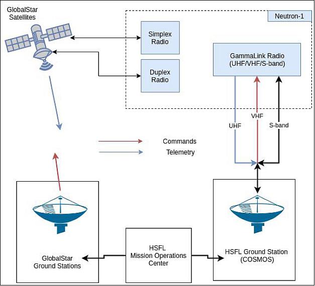
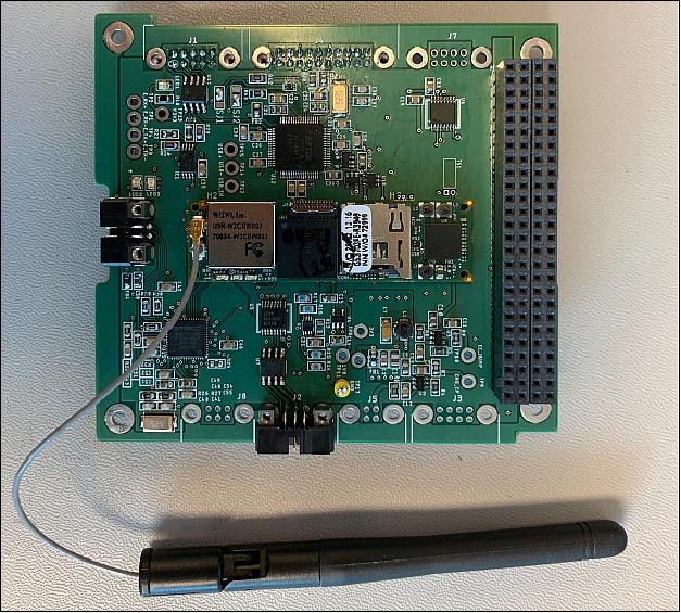
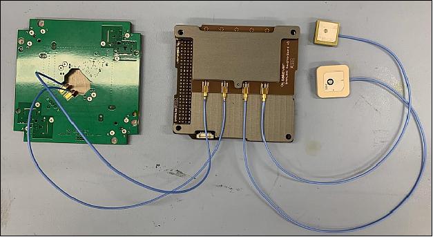
The Gamalink Software Defined Radio (SDR) is developed by Tekever with the purpose to enable future satellite networks (constellations, formation flying mission, etc.). The Gamalink provides VHF uplink commands, UHF telemetry/beacon downlink, S-band downlink for science data, S-band uplink for software updates. This particular SDR also receives GPS signals and provides a GPS time and position state vector when lock is achieved. This GPS is used as a redundant GPS. The Gamalink SDR and antennas are shown in Figure 6.
The other communication system on board the Neutron-1 is the GlobalStar radio GSP-1720, a duplex radio system that enables a near continuum stream of data when operating under GlobalStar coverage. Additionally there is a GlobalStar radio STX-3 for simplex messages relaying to the ground very small packets of information (144 bytes every 10 min) which allow ground operators to quickly check the overall status of the spacecraft.
COSMOS Software: All aspects of software; flight, ground and mission operations are implemented using the HSFL COSMOS Software Framework (http://cosmos-project.org). The key operational concepts of this Framework as it relates to the Neutron-1 mission are:
• Reliance on standards: User interfaces are implemented over a web framework. All information is represented in JavaScript Object Notation (JSON), both on disk and over the network. All Command and Control is implemented as Native OS programs (clients and servers). Everything is transferred as either files or network packets. All network communication is performed via IPV4 UDP packets.
• Generalization of complex devices: All devices are simplified to their most general basics and then hidden behind COSMOS "Agents" running as Native OS servers.
• Modularization: Subsystems and/or Devices are broken out as Agents. Specific functionalities are broken out as Requests to an Agent. Every possible Command is accessible from the Native OS command line.
• Reuse of components: A number of Agents are used in every aspect of operations. Other Agents are constructed so as to operate in a common way at the System level, while behaving uniquely at the device level.
Development Status
Neutron-1 is expected to launch in the Fall 2019 while the LunaH-Map mission is expected to launch in 2020. This will allow the LunaH-Map team to test the instrument operations in Low Earth Orbit (LEO) prior to launching the instrument to Lunar orbit. The satellite will be delivered to NanoRacks in August 2019.
Launch
The Neutron-1 CubeSat will be launched in October 2019 on the NASA sponsored ELaNa 25 mission carrying 15 CubeSat missions to the ISS. The launch vehicle of this NG-12 (Northrop Grumman-12) Cygnus logistics payload flight is the Antares II rocket (230 configuration) from the Wallops Flight Facility, VA. 6)
Orbit: Since Neutron-1 is deployed from the ISS, the orbit will be approximately circular at ~400 km with an inclination of 51.6º.
Secondary CubeSat Payloads of the Northrop Grumman-12 Cygnus flight
• Argus, a 2U CubeSat (2.5 kg) of St. Louis University, Missouri. Argus' mission is to improve the ability to model the effects of space radiation on modern electronics.
• AzTechSat-1, a 1U CubeSat technology mission of NASA Ames Research Center, Moffett Field, California
• CAPSat Cooling, Annealing, Pointing Satellite), a 3U CubeSat (4 kg) of the University of Illinois at Urbana – Champaign
• CryoCube, a 3U CubeSat developed by NASA KSC (Kennedy Space Center) to perform cryogenic fluid management experiments.
• CySat-1 (Cyclone Satellite-1), a 3U CubeSat technology demonstration mission of Iowa State University.
• HARP (Hyper Angular Rainbow Polarimeter) – University of Maryland, Baltimore County, Maryland - to measure the microphysical properties of cloud water and ice particles.
• Neutron-1, a 3U CubeSat developed by students of the UHM (University of Hawaii, Manoa).
• Phoenix, a 3U CubeSat of ASU (Arizona State University), Tempe, AZ.
• RadSat-U (Radiation Satellite), a 3U CubeSat demonstration mission of Montana State University, Bozeman, MT.
• SOCRATES (Signal of Opportunity Cubesat Ranging and Timing Experiments), a 3U CubeSat of the University of Minnesota, Minneapolis.
• SORTIE (Scintillation Observations and Response of The Ionosphere to Electrodynamics), a 6U CubeSat led by ASTRA (Atmospheric & Space Technology Research Associates), Boulder, Colorado. The team is composed of ASTRA, COSMIAC, AFRL, University of Texas at Dallas and Boston College. COSMIAC is the satellite integrator.
• SPOC (Spectral Ocean Color), a 3U CubeSat (4 kg) demonstration mission of the University of Georgia, Athens, GA.
• TJREVERB (Thomas Jefferson High School for Science and Technology Research and Education Vehicle for Evaluating Radio Broadcasts), a 2U CubeSat for communication experiments, Alexandria, Virginia.
External Cygnus Deployments
• HuskySat, a 3U CubeSat technology demonstration mission (plasma propulsion) of the University of Washington, Seattle, WA.
• SwampSat II, a 3U CubeSat technology demonstration mission of the University of Florida, Gainesville, FL.
Once aboard the ISS, the Neutron-1 satellite is expected to be deployed in early 2020 from the NanoRacks CubeSat Deployer (NRCSD).
Sensor Complement
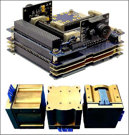
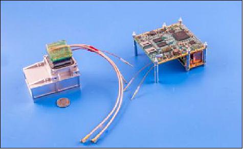
The mission's primary payload is designed to use the scintillator material CLYC (Cs2 LiYCl6) to measure count rates of epithermal neutrons. The instrument is contributed to the Neutron-1 program by Arizona State University as part of the Lunar Polar Hydrogen Mapper (LunaH-Map) mission (Ref. 5). The payload consists of a single flight spare neutron detector module from the LunaH-Map Miniature Neutron Spectrometer (Mini-NS). LunaH-Map will enter lunar orbit and measure the epithermal neutron count rates above south pole's permanently shadowed regions to place constraints on the abundance and distribution of water ice that may be trapped within those regions. The Mini-NS is an eight module detector array where each module, pictured in Figure 7 on the left, within the arrays are controlled by an electronics board assembly pictured in Figure 7 on right (Ref. 2). 7)
For Neutron-1, the module and electronics board assembly functionality and performance will be evaluated in the space environment, in preparation for the LunaH-Map mission which will launch on the Space Launch System (SLS) Exploration Mission 1 (EM-1) in 2020 or later. Instrument telemetry, health and safety information, neutron data products, and pulse shape discrimination parameter data will be downlinked from the payload for evaluation of the detector performance. Data collection with the detector operating in the positive and negative spacecraft velocity directions as well as pointing nadir and zenith will enable a qualitative assessment of detector performance throughout the operational temperature ranges.
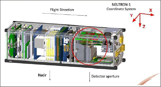
The detector is covered with a gadolinium shield, which has a high thermal neutron cross section, on the nadir face, as shown in Figure 8, which makes the instrument sensitive to epithermal neutrons from 0.4 eV to 10 keV in energy (the neutron energy region primarily sensitive to hydrogen abundance). This will enable the detector to measure the upward and downward epithermal neutron flux in LEO by reorienting the spacecraft. Assessment of data collected in these orientations may help place useful constraints on the detector performance, as well as demonstrate the feasibility of future neutron payloads that may measure the directionality of the LEO low energy neutron environment, or for considerations with respect to experiments for measuring the neutron lifetime.
Ground Segment
HSFL operates and maintains a UHF, VHF, and L/S-band amateur ground station for satellite operations at the Kauai Community College (KCC). This ground station is integrated with our in-house developed (and open source) COSMOS software to facilitate coordination of equipment, and tracking of satellites. Using COSMOS, this system is capable of complete automation of satellite contacts. The ground station is also manually controllable and assisted with Orbitron. HSFL also partners with the Naval Postgraduate School on the operation of the MC3 ground station at the UH Manoa Campus. The KCC ground station will be used as the primary operations station of the Neutron-1 mission. Figure 9 shows the full ground capabilities at the University of Hawaii.
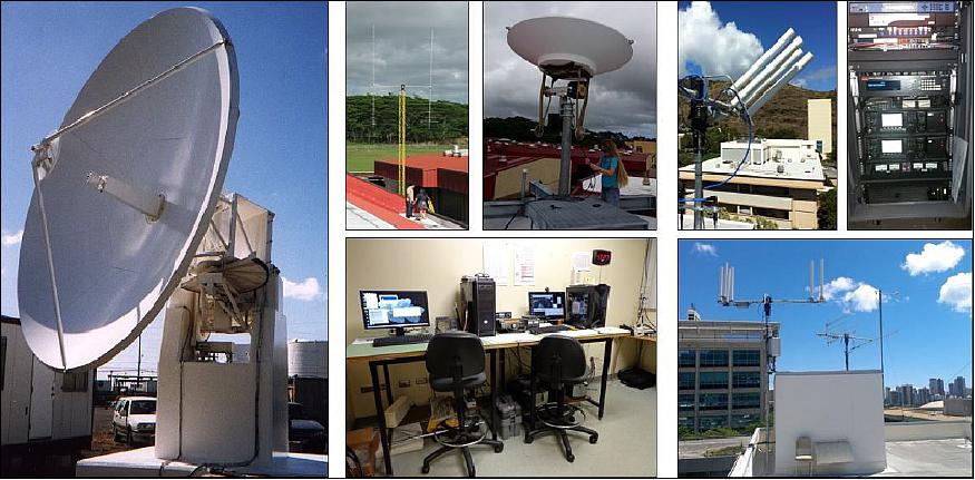
The KCC ground station uses an ICOM IC-9100 as the main radio for the VHF uplink channel to the Gamalink. This radio is connected to a M2 Antenna 2MCP22 controlled with a Yaesu G-5500 rotor. The ICOM IC-9100 is also the main radio for the downlink channel of the Gamalink. This radio is connected to a M2 Antenna 2MCP22 controlled with a Yaesu G-5500 rotor (this is a similar setup but separate system from the VHF). The radios and antennas are operated via COSMOS running in Linux.
The Gamalink Ground station radio is used for the S-band uplink/downlink channel. This radio is connected to a M2 Antenna AZEL1000 controlled with a M2 Antenna RC2800PRKX2SU rotor. The radio and antenna are operated via the Gamalink ground software and COSMOS running in Linux.
References
1) Miguel A. Nunes, Lloyd French, Peter A. J. Englert, Eric Pilger, Lance Yoneshige, Isaac Rodrigues, Yosef Ben, Gershom, Amber Imai-Hong, Kasey Hagi, Craig Opie, Luke P. Flynn, Craig Hardgrove, Bob Roebuck, "Neutron-1 Mission: Low Earth Orbit Neutron Flux Detection and COSMOS Mission Operations Technology Demonstration," Proceedings of the 33rd Annual AIAA/USU Conference on Small Satellites, August 3-8, 2019, Logan, UT, USA, paper: SSC19-WKVII-02, URL: https://digitalcommons.usu.edu/cgi/v
iewcontent.cgi?article=4423&context=smallsat
2) C. Hardgrove, S. T. West, L. E. Heffern, E. Johnson, J. Christian, R. Starr, T. Colaprete, "Development of the Miniature Neutron Spectrometer for the Lunar Polar Hydrogen Mapper mission." 49th Lunar Planet. Science Conference 2018(LPIContrib.No.2083) , Abstract #2341, URL: https://www.hou.usra.edu/meetings/lpsc2018/pdf/2341.pdf
3) C. Hardgrove, J. Bell, J. Thangavelautham, A. Klesh,R. Starr, T. Colaprete, M Robinson, D. Drake, E. Johnson, J. Christian, A. Genova,D. Dunham, B.Williams, D. Nelson, A. Babuscia, P. Scowen, K. M. Cheung, T. McKinney, A. Taits, V. Hernandez, P. Wren, A. Thoesen, A. Godber, M. Beasley, "The Lunar Polar Hydrogen Mapper (LunaH-Map) Mission: Mapping Hydrogen Distributions in Permanently Shadowed Regions of the Moon's South Pole," Annual Meeting of the Lunar Exploration Analysis Group, held 20-22 October, 2015 in Columbia, Maryland. LPI Contribution No. 1863, p.2035, October 2015
4) C. Hardgrove, J. F. Bell,. R. Starr, A. Colaprete, D. Drake, I. Lazbin, S. West, E. B. Johnson, J. Christian, L. Heffern, A. Genova, D. Dunham, B. Williams, D. Nelson, S. Puckett, A. Babuscia, P. Scowen, H. Kerner, R. J. Amzler, "Development of the Lunar Polar Hydrogen Mapper Mission," New Views of the Moon 2 - Asia, Proceedings of the conference held 18-20 April, 2018 in Fukushima, Japan. LPI Contribution No. 2070, 2018, id.6024, April 2018
5) M.M.Bourne, C.Mussi, E. C.Miller, S. D. Clarke, S. A. Pozzi, A. Gueorguiev,"Characterization of the CLYC Detector for Neutron and Photon Detection," Nuclear Instruments and Methods in Physics Research Section A: Accelerators, Spectrometers, Detectors and Associated Equipment, Volume 736, 1 February 2014, Pages 124-127, https://doi.org/10.1016/j.nima.2013.10.030,
6) "Upcoming ELaNa CubeSat Launches," NASA, ELaNa 25, URL: https://www.nasa.gov/content/upcoming-elana-cubesat-launches
7) S. West, C. Hardgrove, R. Starr,E. B. Johnson, J. Christian, A. Genova, A. Colaprete, D. Nelson, "LunaH-Map Miniature Neutron Spectrometer Response Over Neutron Suppressed Regions," Lunar and Planetary Science XLVIII(2017), URL: https://www.hou.usra.edu/meetings/lpsc2017/pdf/2909.pdf
The information compiled and edited in this article was provided by Herbert J. Kramer from his documentation of: "Observation of the Earth and Its Environment: Survey of Missions and Sensors" (Springer Verlag) as well as many other sources after the publication of the 4th edition in 2002. Comments and corrections to this article are always welcome for further updates (eoportal@symbios.space).
Spacecraft Launch Payload Ground Station References Back to top