Oculus-ASR (Oculus-Attitude and Shape Recognition)
Non-EO
Quick facts
Overview
| Mission type | Non-EO |
| Launch date | 25 Jun 2019 |
Oculus-ASR (Oculus-Attitude and Shape Recognition)
Oculus-ASR is a microsatellite designed and built by undergraduate students of MTU (Michigan Technological University), Houghton, MI, USA. The goal of Oculus-ASR is to exercise and validate techniques for determining an orbiting object's pose using unresolved ground imagery. The nanosatellite has been optically characterized in an AFRL ground facility to determine reflective signatures that can be expected on orbit. Once on orbit, the Oculus-ASR will be monitored by ground-based telescopes and these observations will be reconciled against "truth" attitude data recorded during various maneuvers. 1)
The Oculus-ASR mission is relevant to "space surveillance technologies" of DoD/AFRL. It is technology demonstration mission used as a calibration satellite for the AMOS (Air Force Maui Optical Station) telescopic non-resolved object characterization program. 2)
In January 2011, the Oculus-ASR team won the 6th UNP (University Nanosatellite Program) competition. The UNP is a national, university-level competition run by the AFRL (Air Force Research Laboratory) and funded by the Air Force Office of Scientific Research. As the winner of this competition, the Oculus-ASR team will receive follow-on support for flight preparation from AFRL staff. 3) 4) 5)
The Aerospace Enterprise is a student organization at MTU (Michigan Technological University) and member of MTU's Enterprise Program. The Enterprise is composed of a diverse multidisciplinary group of over 50 students. Students work together on innovative and relevant Aerospace related projects, and all members contribute towards achieving specific project goals. Through the Aerospace Enterprise students are able to enhance their engineering and Aerospace knowledge, as well as develop personal and leadership skills that will provide valuable work experience before graduation. Additionally, students work closely with industry sponsors whose contributions play a vital role to the Enterprise's success. 6) 7)
Background: As access to space has become more common, the number of objects orbiting Earth has increased drastically. Some of these objects are functional satellites that perform vital operations for commercial or military purposes. However, many of the objects orbiting Earth are debris made up of defunct satellites, spent rocket stages, and the ruins of satellites destroyed in anti-satellite weapon tests or collisions. These objects pose a growing threat to functional satellites. Collisions with orbital debris can cause damage to essential commercial and military assets that would render them useless. Therefore, it is beneficial for the space community to have an accurate knowledge of the current and future locations of orbiting objects. The effort to identify, catalog, and track the objects orbiting Earth, both functional and nonfunctional, is part of the overall SSA (Space Situational Awareness) activity.
Ground-based optical telescopes are one key instrument in achieving SSA. In addition to determining the trajectory of an orbiting object, optical telescopes can also be used to determine the object's attitude, physical profile, and features. A drawback of using optical telescopes for such ASR (Attitude and Shape Recognition) is the fundamental limitation of resolvability. Orbiting objects become unresolvable at high orbits or small telescope apertures. In fact, many orbiting objects fall outside the resolvable range of most ground-based telescopes. Under these conditions, a telescope sees the object as a point-source of light and it is impossible to distinguish features of the object from the telescope image.
While spatial features cannot be determined from unresolved "dots" of light, these dots contain spectral and photometric information that can be used to deduce properties of the object. Using unresolved imagery to observe and characterize orbiting objects with the goal of determining their attitude and detecting configuration changes (e.g. deployments) is important. This is accomplished by analyzing the spectral frequencies and temporal changes in the intensity contained in the point-source of light and referencing the measured signals with known spectral signatures. If successful, this technique could lead to an inexpensive network of sensors with broad coverage.
Given an orbiting object with known optical properties it is relatively straightforward to predict the observed signature if the object's attitude or maneuver is specified.
This objective of Oculus-ASR mission focuses on the inverse problem: given a measured optical signature generated by an object with known properties - is it possible to calculate the object's attitude? While, in principle, this problem can be addressed, the algorithms are non-trivial and require validation and/or calibration. Calibration opportunities are rare as they require pre-characterization or at least optical modeling of the orbiting object to create a signature database prior to launch.
Spacecraft
Oculus-ASR is a microsatellite being developed through a collaboration between MTU (Michigan Technological University) and AFRL. Once on orbit the Oculus-ASR will serve as a cooperative imaging target for ground-based telescopes. Ground controllers at MTU will command the vehicle to perform various attitude maneuvers during overflights of these telescopes. After each ground-viewing opportunity, the MTU team will provide attitude truth history to the telescope observers for comparison with their findings.
The Oculus-ASR microsatellite has a mass of 70 kg with a volume envelope of 48 cm x 48 cm x 79 cm. It consists of two modules that are permanently attached. An octagonal module, referred to as the Oculus module, sits atop a square module, known as the ASR module. Figure 1 shows the assembled vehicle and identifies the major features on the exterior of the microsatellite.
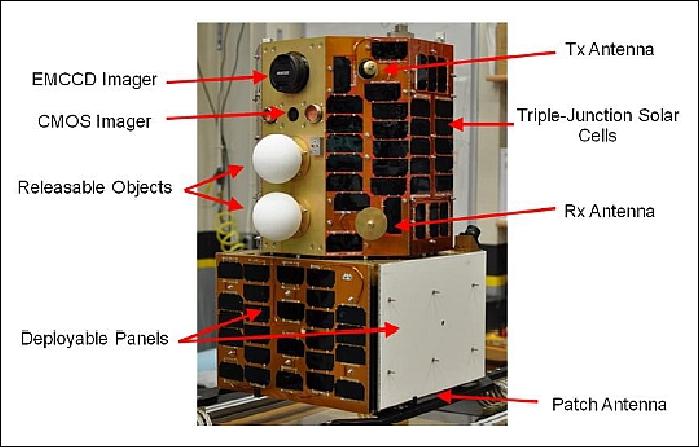
Each of the four sides on the ASR module (bottom) has a deployable panel. Three of these panels are covered with solar cells. The fourth is covered in Duraflect material. Duraflect is a highly reflective, diffuse white coating used as an optical standard for characterization and calibration measurements. Under and on the back of each deployable panel are specific materials requested by telescope operators for their distinct spectral characteristics. These materials are red, blue, yellow, and clear anodized aluminum. Each panel is deployed separately through the actuation of Frangibolt actuators. Spring-loaded hinges then lift the panel until it locks in place 90º from its undeployed position. These deployable panels allow the spectral signature of Oculus-ASR to be changed multiple times over the course of the mission by altering the vehicle's shape and exposed materials.
Two releasable objects are mounted to the Oculus module. These objects are approximately 10 cm in diameter and will be used to provide ground observers an opportunity to view small, closely spaced objects. The releasable objects are coated in the same Duraflect material used on the deployable panel, and can be released individually using the same style of Frangibolt actuator used for the deployable panels. These objects then drift from the vehicle due to the force exerted from the actuator.
The spacecraft is 3-axis stabilized. This allows Oculus-ASR to perform a wide variety of attitude maneuvers for telescope calibration purposes. Attitude determination is accomplished using a Bartington Mag-03MRN magnetometer and three Silicon Sensing SiRRS01-05 gyroscopes. These sensors provide an attitude reading accurate to within 5º of error. Actuation is provided with 3 reaction wheels and three magnetic torque rods. Both reaction wheels and torque rods were developed in-house at Michigan Technological University. Each magnetic torque rod can generate approximately 285 µNm of torque. A single reaction wheel is capable of 11 mN·m of torque. The reaction wheels allow the vehicle to achieve an angular velocity of 7.5º/s on its x- and y-axes, and up to 17º/s on its z-axis.
Concept of Operations
Oculus-ASR will serve as an imaging calibration target for ground-based observatories tasked with characterizing spacecraft. Oculus-ASR has been designed with attitude determination algorithms that allow ground users to control the spacecraft's orientation and change its shape during the mission – presenting an ever-changing target for ground telescopes.
Oculus-ASR will exercise three key capabilities of telescopes using unresolved optical imagery: determine the spacecraft's attitude, detect configuration changes, and measure the change in signature due to a small resident space object in close vicinity to the main vehicle.
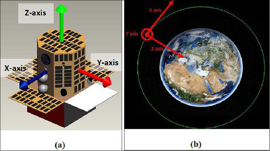
On-orbit, one of Oculus-ASR's roles will be to fulfill requests to view specific attitude profiles during overpasses of the observatory. These attitude profiles are described with regard to a BCS (Body Coordinate System) and an orbital coordinate system. Figure 2 depicts these coordinate systems.
Telescope operators may select maneuvers from a list of predetermined attitude profiles. These include:
• Ready: Rotation rate about any axis is less than 2º/s; the angles between the BCS and Orbital Coordinate System are uncontrolled.
• Fixed-Axis Rotation: Any single body coordinate axis is fixed with respect to the Orbital Coordinate System; constant rotation rate about the fixed axis, no rotation about any other axis.
• Earth Pointing: A vector in the BCS is kept pointed at a fixed location on the Earth's surface.
• Orbital Coordinate System Fixed Attitude: Constant angles between the BCS and Orbital Coordinate System with zero rotation; attitude is constant with respect to the Orbital Coordinate System.
• Sun Pointing: A vector in the BCS is kept pointed at the Sun.
Observatories will schedule these maneuvers with the operators of Oculus-ASR in advance of an observation opportunity. At all times, Oculus-ASR will be recording a time-indexed history of its attitude. After an overpass maneuver, this attitude history will be downloaded to the MTU ground station, where it will be delivered to the telescope operators. Telescope operators will then be able to use the truth attitude from the vehicle and the models developed through the ground characterization of the vehicle to determine if the telescope was providing readings accurate enough to determine Oculus-ASR's attitude during the observation.
Oculus-ASR is also capable of changing its physical configuration through the use of deployable panels. Deployment of a panel changes both the projected profile of the vehicle and the exposed materials on the exterior of the vehicle. Each panel exposes a spectrally distinct material. There are a total of four deployable panels on the satellite, which can be deployed individually to provide four distinct changes in Oculus-ASR's physical configuration. - Once deployed the panels cannot be retracted. After establishing baseline measurements of the vehicle in its as-launched configuration, telescope operators will request the deployment of a panel. The operators of Oculus-ASR will command the deployment and confirm the successful opening of a panel. Telescope operators can then take further measurements and compare these to the baseline measurements in order to determine which panel was opened and when the actuation occurred.
Finally, Oculus-ASR is equipped with two releasable objects. These objects are much smaller than Oculus-ASR. After an object is released, it drifts slowly from the vehicle. The goal of the telescope operators is to determine if and when this small object can be detected and distinguished from the Oculus-ASR. The ideal method of accomplishing this will be to release the object at the beginning of the first of two consecutive overpasses of an observatory. This gives telescope operators an additional opportunity to view the satellite and the separated object in the event that the separation cannot be detected during the first observation opportunity.
Vital to all of these operations is having a complete radiometric characterization of the vehicle prior to launch. This characterization yields models that can be used as truth values to which the experimental measurements taken from the telescopes can be compared.
Launch
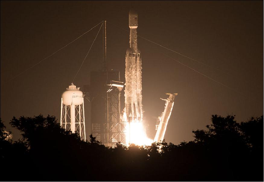
OCULUS-ASR is a secondary payload on the STP-2 rideshare mission of USAF, launched on 25 June 2019 (06:30 UTC) aboard a SpaceX Falcon Heavy launch vehicle from Launch Complex 39A at NASA's Kennedy Space Center. The STP-2 payload includes six FormoSat-7/COSMIC-2 satellites (primary payload, each with a mass of 280 kg), developed by NOAA and Taiwan's National Space Organization to collect GPS radio occultation data for weather forecasting. The mission also carries several NASA technology demonstrations. The STP-2 mission is led by the Air Force Space Command's Space and Missile Systems Center (SMC). The total IPS (Integrated Payload Stack) has a mass of 3700 kg. 9)
Secondary Payloads
• DSX (Demonstration and Science Experiments) mission of AFRL
• GPIM (Green Propellant Infusion Mission), a demonstration minisatellite of NASA (~180 kg). 10)
• FalconSat-7, a 3U CubeSat mission developed by the Cadets of the U.S. Air Force Academy (USAFA) at Colorado Springs, CO.
• NPSat-1 (Naval Postgraduate School Satellite-1) of the Naval Postgraduate School, Monterey, CA. A microsatellite of 86 kg.
• OCULUS-ASR (OCULUS-Attitude and Shape Recognition), a microsatellite (70 kg) of MTU (Michigan Technological University), Houghton, MI, USA.
• Prox-1, a microsatellite (71 kg) of SSDL (Space Systems Design Laboratory) at Georgia Tech.
• LightSail-2 of the Planetary Society, a nanosatellite (3U CubeSat, 5 kg) will be deployed from the parent satellite Prox-1.
• ARMADILLO of UTA (University of Texas at Austin), a nanosatellite (3U CubeSat) of ~ 4 kg.
• E-TBEx (Enhanced Tandem Beacon Experiment), a tandem pair (3U CubeSats) of SRI International.
• Prometheus-2.1 to -2.8, seven 1.5U CubeSats (each of 2 kg) of LANL (Los Alamos National Laboratory).
• TEPCE (Tether Electrodynamics Propulsion CubeSat Experiment), a 3U CubeSat (3 kg) of NPS (Naval Postgraduate School).
• CP-9 , a joint CP-9/StangSat experiment, which is a collaboration between PolySat at Cal Poly and the Merritt Island High School, and is sponsored by the NASA LSP (Launch Services Program). CP-9 is a 2U CubeSat while StangSat is a 1U CubeSat.
• PSat-2 (ParkinsonSat-2), a student built 1.5U CubeSat of USNA (US Naval Academy) with a mass of 2 kg.
• BRICSAT-2, a student built 1.5U CubeSat of USNA (US Naval Academy) to demonstrate a µCAT electric propulsion system and carry a ham radio payload.
• OTB-1 (Orbital Test Bed-1) a minisatellite developed by SSTL (based on the SSTL-150 bus, 138 kg) and owned by General Atomics' Electromagnetic Systems Group (GA-EMS) of San Diego. One of the hosted payloads is NASA's DSAC (Deep Space Atomic Clock), a technology demonstration mission with the goal to validate a miniaturized, ultra-precise mercury-ion atomic clock that is 100 times more stable than today's best navigation clocks.
Orbits
The STP-2 mission will be among the most challenging launches in SpaceX history with four separate upper-stage engine burns, three separate deployment orbits, a final propulsive passivation maneuver and a total mission duration of over six hours. It will demonstrate the capabilities of the Falcon Heavy launch vehicle and provide critical data supporting certification for future National Security Space Launch (NSSL) missions. In addition, [the USAF] will use this mission as a pathfinder for the [military's systematic utilization of flight-proven] launch vehicle boosters.
The three orbits of the STP-2 mission for spacecraft deployment are:
1) The small secondary CubeSat satellites will be deployed into an elliptical orbit of ~300 x 860 km, inclination of ~28º. These are: OCULUS-ASR, TEPCE, E-TBEx, FalconSat-7, ARMADILLO, PSAT-2, BRICSAT, and CP-9/StangSat.
2) The second deployment batch of the STP-2 mission will occur at a circular altitude of 720 km and an inclination of 24º.
- Deployment of LightSail-2, Prox-1, and NPSat-1
- Deployment of OTB-1 with NASA's DSAC and GPIM
- The six FormoSat-7/COSMIC-2 satellites will be deployed into the initial circular parking orbit of 720 km. Eventually, they will be positioned in a low inclination orbit at a nominal altitude of ~520-550 km with an inclination of 24º (using their propulsion system). Through constellation deployment, they will be placed into 6 orbital planes with 60º separation.
3) The third and final deployment will be the Air Force Research Lab's DSX spacecraft as well as the ballast, which will be delivered to an elliptical MEO (Medium Earth Orbit) with a perigee of 6000 km and an apogee of 12000 km, inclination of 43º.
Pre-launch Characterization
SSA (Space Situational Awareness) relies not only on measurements of space objects but on an understanding of what those measurements mean. In order to understand the signatures of space objects, it is necessary to measure, model, and simulate the spatial characteristics of spacecraft. One of the objectives of the Oculus-ASR characterization experiment was to provide ground-truth satellite data for the construction and validation of predictive computer models such as those used in TASAT (Time-domain Analysis Simulation for Advanced Tracking), a satellite modeling code used throughout the SSA community. Another objective of this experiment is to establish if pose determination is possible solely from on-orbit spectral returns. Imaging the satellite on the ground will help ascertain whether or not this objective can be met (Ref. 4).
Multispectral optical measurements of the Oculus-ASR satellite were conducted at an AFRL (Air Force Research Laboratory ) far-field optical measurement facility by an AFRL program. This facility allows accurately simulated observations of space objects without significant atmospheric effects. This ability provides the opportunity to measure the optical signatures of satellites and then modify corresponding satellite models to improve agreement with these ground-truth optical signatures. This characterization experiment obtained accurate far-field imagery, OCS (Optical Cross Section), and spectral-polarimetric glint and off-glint data helpful in validating remote observations.
The use of anodized colored panels on the Oculus-ASR satellite base was intended for the purpose of inferring satellite pose or attitude from observations. Satellite imagery for typical on-orbit viewing geometries will not be resolved. In certain poses, when the satellite is observed from the ground, metallic glints or non-colored panel reflections will often dominate the OCS and mask the colored panel contributions. It is important to understand which spectral filtered wavebands will contribute the most attitude information. Common astronomical filters are: V-band (550 nm center wavelength with a nominal FWHM (Full Width Half Maximum) specification of 90nm), and I-band (800 nm center wavelength with a nominal FWHM specification of 150 nm); often, these bands along with broadband images are obtained. The Oculus-ASR ground-truth characterization acquired broadband, V-band, I-band, and 650 nm narrow band (10 nm bandpass) filtered images as well as spectral data spanning the 350 nm - 2500 nm wavelength range.
TASAT modeling and simulation: Several different predictive models of the Oculus-ASR satellite were built for use in TASAT. The models were built using engineering diagrams, documentation photos, and visual inspection of the satellite. A total of four models were built, with different features on each. The first and second models have the wing panels secured down, both with and without the deployable spheres attached. The second and third models have the wing panels deployed, both with and without the spheres attached. The left side of Figure 5 shows a rendered image of the satellite model with the colored wing panels secured down and the sphere deployed; the right side of the figure shows a rendered image of the satellite model with the wings deployed but the spheres attached. These renderings were generated directly from the 3D satellite model.
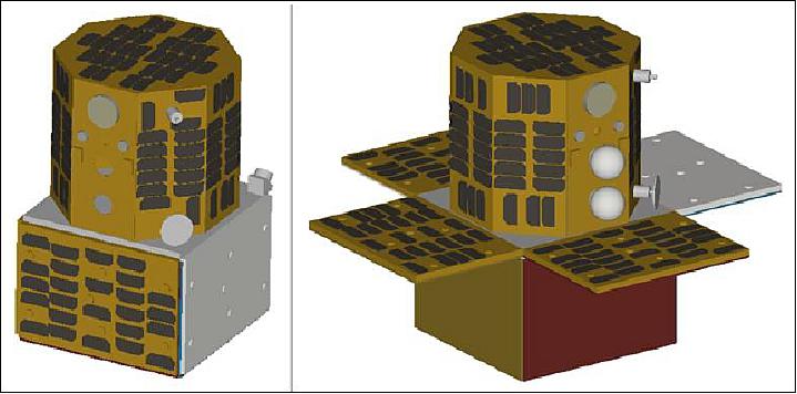
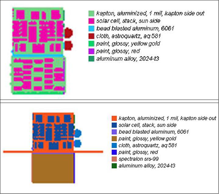
Figure 6 shows the material breakdown on two of the models. The materials used on the model are shown in decreasing order of percent contribution to the surface area given the orientation. The materials were selected based on a description of the materials visible on the satellite. Note that two additional models were built similar to this, the only difference being that the spheres were removed. The same materials were used for those models as well.
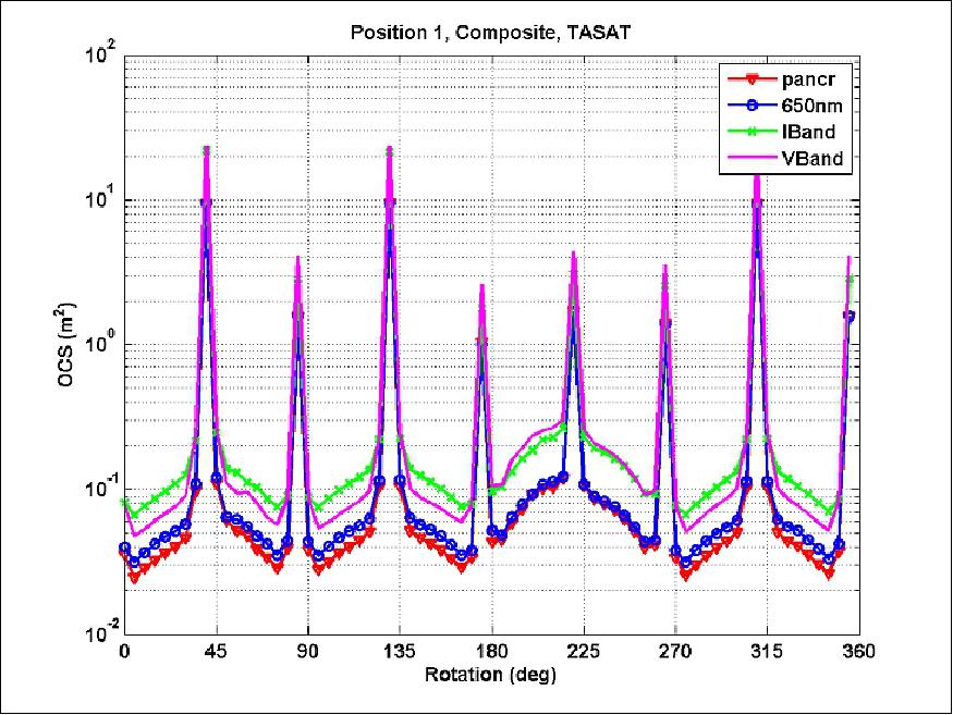
TASAT simulations were conducted in order to compare predicted imagery with the ground truth imagery. The satellite was "posed" in TASAT to stimulate facility measurement geometries. The same wavebands were also used in the simulations. The simulated OCS data for all wavebands is shown in Figure 7. Eight strong glints are prominent in the plot corresponding to the solar panel glints. The strongest glints represent the reflection from the solar panels on the octagonal structure and the solar panels on the base. The weaker glints correspond to only glints from the octagon, as the base was at a corner at these rotation angles.
Sensor Complement
PIXIS (PIXIS camera of Princeton Instruments)
PIXIS is a digital scientific imaging camera providing 16 bit data in the range of 400-900 nm. Filtered waveband images are acquired at 4 wavebands: V-band (550 nm center wavelength with a nominal FWHM (Full Width Half Maximum) specification of 90 nm), I-band (800 nm center wavelength with a nominal FWHM specification of 150 nm, 650 nm waveband with 10 nm bandpass, and broadband. An ASD (Analytical Spectral Devices) spectrometer is used during the data collection as well. The ASD provides continuous spectral information from 350-2500 nm. A 6-DOF robotic arm is used to pose the satellite (Ref. 1).
PIXIS imagery: Figure 8 shows PIXIS imagery for satellite rotations of 20° (off-glint), 90° (octagon glint), and 135° (octagon and base glint) in the I-band for two positions, position 1 with the panels secured down and position 2 with the panels deployed. Note that because of the choice of reference material (based on the satellite radiance), the image scaling is different between the first image and the next two images. Because of the large dynamic range between the glint and off-glint rotations, both glass and Spectralon were used as references. These PIXIS images are used to calculate the OCS data that follows (Ref. 4).
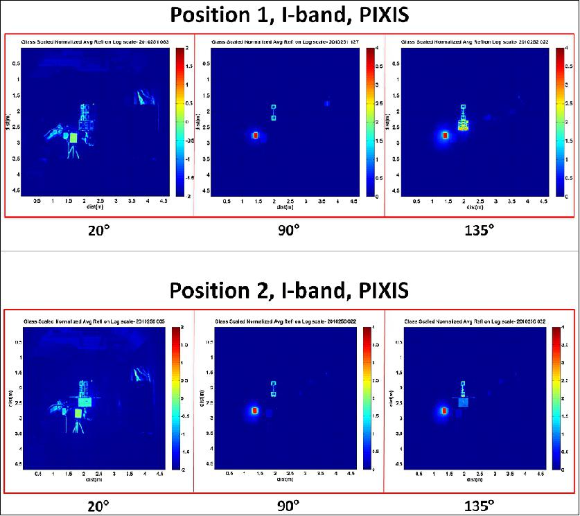
Legend to Figure 8: Note that in position 2, the colored panels on the base of Oculus-ASR are deployed. For rotation angles of 45°, 135°, and 315°, both the colored panel and the top solar panel glint; for rotation angle 225°, only the red colored panel glints. The solar panel peak glints (0°, 90°, 180°, and 270°) are not resolved and the solar panel glint width is smaller than that for the colored panels. This is evident in Figure 9.
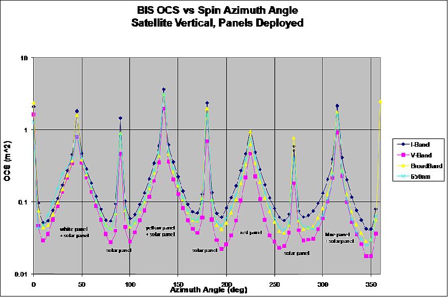
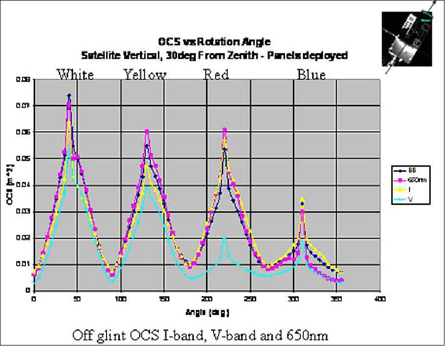
It is not likely for ground-based telescopes to observe sharp solar panel glints unless special efforts are made to align the satellite appropriately. More likely geometries are off-glint positions where the satellite is not completely nadir-pointing, as in position 2.2. Please note the glyph in the top right corner of Figure 10. In some figures, the glyph has been transposed so the illumination angle is different. This does not affect the analysis. OCS results for the Oculus-ASR satellite while in position 2.2 are shown in Figure 10. Because the geometry is off-specular, the OCS values are less than 0.1 m2. The visible colored panel is labeled in the figure. Sharp solar panel glint contributions are not apparent in this position; the four peaks in the plot are associated with the colored panels.
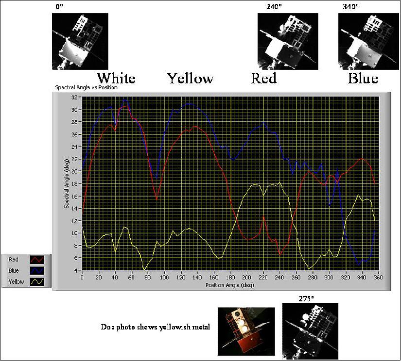
The spectral angles or correlations are shown in Figure 11. As seen in the figure, when the red coupon serves as the reference (the red line), the spectral angle is minimum when the red panel is prominent on the satellite. Similarly, the spectral angle when the blue coupon is used is minimum when the blue panel is prominent. In further examination of the plot, when the yellow coupon is used as a reference, there are a few minimums suggesting that the yellow-gold reflection of the satellite bus rather than just the yellow colored panel is influencing the results. Also as seen in the figure, the yellow coupon reference correlates strongly with the white panel. Because of the choice of filter bands, the discrimination between the yellow, red, and blue panels is not good.
In summary, a successful ground-truth characterization experiment was performed on the Oculus-ASR satellite. Optical signatures of the satellite were acquired which were then used to build the 3D predictive satellite models. Based on the accurate imagery and glint and off-glint ground truth data collected, the predictive models were validated and improvements were made to the simulation and materials database in order to improve simulated and ground truth optical satellite signature agreement.
It is concluded that determination of which colored panel of the Oculus-ASR is most visible from on-orbit spectral data is plausible upon analysis of ground truth data. Pose determination can then be estimated based on the most prominent colored panel visible. However, the current satellite material choices and the chosen wavebands that data was acquired in were not optimum. One change that may improve spectral signature collection and pose determination would be to change the panel colors from red, yellow, and blue, to red, green, and blue. The spectral difference between these colors is greater than the first set of colors. Also, using more diffuse materials such as a diffuse colored paint may provide larger signals at non-specular geometries. The choice of wavebands to acquire data in was not optimum. RGB 50 nm FWHM filters would work best with the recommended panel color change. Additionally, a polarizer may remove much of the first surface reflection which will increase the difference in spectral signal among wavebands.
The objectives of the Oculus-ASR mission stated in the introduction were successfully completed. A ground-truth characterization of the spacecraft was performed to aid in the understanding of space object signatures for SSA. Based on the ground-truth characterization data, successful construction and validation of predictive computer models was accomplished. And an investigation in pose determination from on-orbit spectral returns was performed (Ref. 4).
References
1) Lyon B. King, Philip Hohnstadt, Kelly Feirstine, "Pre-launch Optical Characterization of the Oculus-ASR Nanosatellite for Attitude and Shape Recognition Experiments," Proceedings of the 25th Annual AIAA/USU Conference on Small Satellites, Logan, UT, USA, Aug. 8-11, 2011, paper: SSC11-VI-2, URL: http://digitalcommons.usu.edu/cgi/viewcontent.cgi?article=1134&context=smallsat
2) Kelly Cole, David Voss, Amanda Pietruszewski, Lyon B. King, Philip Hohnstadt, Kelly Feisstine, John Crassidis, Michael D'Angelo, Richard Linares, "Space Surveillance Tech Area Benefits from University Partnerships," 2011, URL: http://www.amostech.com/TechnicalPapers/2011/Poster/COLE.pdf
3) Marcia Goodrich, "Blast Off! Tech Students' Winning Satellite to Be Launched into Orbit,! Michigan Tech News, January 20, 2011, URL: http://www.mtu.edu/news/stories/2011/january/story36271-print.html
4) Lyon B. King, Jacob A. LaSarge, "The Oculus-ASR: An Orbiting Nanosatellite Testbed for Non-Resolved Object Characterization," Advanced Maui Optical and Space Surveillance Technologies Conference, 2012 (AMOS 2012), Maui, HI, USA, Sept. 11-14, 2012, URL : http://www.amostech.com/TechnicalPapers/2012/NROC/LASARGE.pdf
5) "OCULUS-ASR Nanosatellite," MTU, URL: https://web.archive.org/web/20160406081959/http://www.aerospace.mtu.edu:80/projects/01%20Oculus-ASR/
6) "Welcome to the Michigan Tech Aerospace Enterprise," MTU, URL: https://web.archive.org/web/20230423160616/http://aerospace.mtu.edu/
7) Andrew Conley, "Oculus-ASR Nanosatellite," MTU, URL: http://www.superiorideas.org/projects/aerospace-enterprise
8) "Oculus-ASR Nanosatellite," MTU, URL: https://web.archive.org/web/20160406081959/http://www.aerospace.mtu.edu:80/projects/01%20Oculus-ASR/
9) Stephen Clark, "Falcon Heavy launches on military-led rideshare mission, boat catches fairing," Spaceflight Now, 25 June 2019, URL: https://spaceflightnow.com/2019/06/25/falcon-heavy-launches-on-military-led-rideshare-mission-boat-catches-fairing/
10) "GPIM Spacecraft to Validate Use of 'Green' Propellant," NASA, Aug. 19, 2014, URL: http://www.nasa.gov/content/gpim-spacecraft-to-validate-use-of-green-propellant/
The information compiled and edited in this article was provided by Herbert J. Kramer from his documentation of: "Observation of the Earth and Its Environment: Survey of Missions and Sensors" (Springer Verlag) as well as many other sources after the publication of the 4th edition in 2002. Comments and corrections to this article are always welcome for further updates (eoportal@symbios.space).