ORS-4 / HawaiiSat-1
EO
Land
Hyperspectral imagers
-
Quick facts
Overview
| Mission type | EO |
| Agency | HSFL |
| Mission status | - |
| Launch date | 04 Nov 2015 |
| End of life date | 04 Nov 2015 |
| Measurement domain | Land |
| Instrument type | Hyperspectral imagers |
| CEOS EO Handbook | See ORS-4 / HawaiiSat-1 summary |
ORS-4 / HawaiiSat-1 Microsatellite Mission
Overview Spacecraft Launch Sensor Complement Ground Segment ORS-4 References
HawaiiSat-1 is a microsatellite developed by the HSFL (Hawaii Space Flight Laboratory) at the University of Hawaii (UH), Manoa, HI. The HawaiiSat-1 mission aims to demonstrate the HU/HSFL's ability to design, launch, and operate satellites. This supports the Department of Defense Office of Responsive Space activities, as well as the research objectives of the University of Hawaii.
The HawaiiSat-1 mission consists of a 55 kg low-Earth orbiting satellite, named HiakaSat (Hyperspectral Imaging, Aeronautical Kinematic Analysis Satellite), which will be the platform for demonstrating a UH-developed long wave infrared hyper-spectral imaging system. In addition, the satellite will be carrying visible color and IR imagers to provide wide and narrow view images of the Earth, and a wide field-of-view star tracker (star camera) for attitude determination. - In Hawaiian, Hiaka means "to recite legends or fabulous stories".
HawaiiSat-1 (HS-1) was a microsatellite mission of 80 kg, which successfully passed CDR (Critical Design Review) in Feb. 2011. However, shortly after that benchmark, the project was required by the ORS (Operationally Responsive Space) Office to reduce the spacecraft mass to 40 kg (later it was raised to 55 kg). To comply with this requirement, the project team modified the HS-1 satellite by cutting it nearly in half, which could be accomplished by reducing the relatively large THI (Thermal Hyperspectral Imager) payload with the much smaller SUCHI (Space Ultra-compact Hyperspectral Imager) payload and eliminating the CRATEX (C-band Radar Transponder Experiment) payload.
Because the new satellite was considered to be a modification of the HS-1 satellite, only a review of the changes was required, without undergoing yet another full PDR and CDR. To avoid confusion, the project team wanted to maintain the name of the mission, "HawaiiSat". To distinguish the new modified HS-1 satellite from the old one, the satellite was named HiakaSat. However, this is just the name of the satellite that is part of the HS-1 mission. Therefore, the launch vehicle ORS-4 / Super Strypi is carrying the HiakaSat payload of the HawaiiSat-1 mission.
The mission goal is to provide a remote sensing capability in LEO for advanced technology and science instrumentation. The HSFL was established at the University of Hawaii for two primary goals:
• To educate students and help prepare them to enter the technical workforce
• To help establish a viable space industry that will benefit the State of Hawai'i.
The primary objectives of the mission are: 3) 4) 5) 6)
1) Demonstrate the ability of the HSFL to design, build, and operate a microsatellite in the 90 kg class as a platform to test new technologies
2) Support the CRATEX (C-band Radar Transponder Experiment) payload
3) Support the testing of the Thermal Hyperspectral Imager (THI) being developed at UH
4) Perform Earth imaging using the HSFL imaging payload.
The HSFL is using a core team of experienced professionals supplemented with graduate and undergraduate students to design, build, and test the HawaiiSat-1 spacecraft within a period of approximately two years from SRR (System Requirements Review) until ready for launch. To keep the spacecraft cost to a minimum, commercial-off-the-shelf (COTS) components will be used when possible. The fairly benign radiation environment of such a low altitude orbit and the use of aluminum sheeting to shield the critical avionics, make the risk of using COTS for a 2-3 year mission to be acceptable while greatly reducing the cost as compared to using space-hardened parts.
- The PDR (Preliminary Design Review) was held in June 2010.
- The CDR (Critical Design Review) was completed in Feb. 2011.
Note: Since the CDR, the project had to make a change due to funding difficulties. The CRATEX payload was removed from the manifest (it will hopefully go on a future satellite); the project is trying get other funding for the payload.
Spacecraft
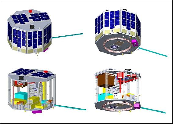
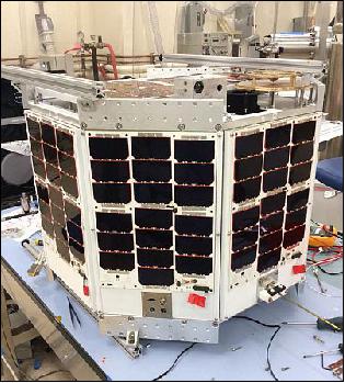
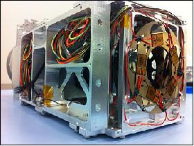
HiakaSat, developed at HSFL, is the microsatellite payload of HawaiiSat-1, an octagonal cylinder in shape with a launch mass of ~ 55 kg. The design life is 6 months.
Bus structure
The design of the spacecraft structure incorporates a number of primary decks supported by a system of struts . The general shape of the structure is an octagon to maximize the power obtained from the solar cells. The solar cell honeycomb substrate doubles as the side panels for the spacecraft and mount onto the vertical and horizontal members. The upper solar panels mount onto the zenith surface of the frame. The material to be used in the structure is Aluminum 7075-T6. A composite structure was considered, but aluminum was selected because of its reduced cost and risk/complexity. The structure is designed for accessibility, which was part of our criteria for a standard baseline bus. Helping this are removable, modular solar panels and external electrical/power feed-throughs. The HawaiiSat-1 design is kept mechanism-free for reduced associated risk and complexity.
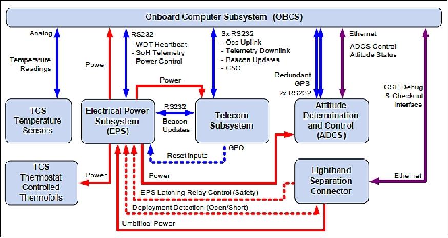
There are three primary subsystems which run at all times:
1) OBCS (On-Board Computer Subsystem): OBCS is the main flight computer which runs the flight software (FSW). The OBCS interfaces with all other bus subsystems using cost effective COTS interfaces including Ethernet, RS232, and an array of analog interfaces specifically for RTD temperature sensors.
2) EPS (Electrical Power Subsystem): EPS is at at the center of the spacecraft power generation, storage, control, and distribution. A single point ground is implemented via the EPS subsystem.
3) Telecommunication (or telecom) subsystem: This subsystem handles all satellite-to-ground segment communications.
ADCS (Attitude Determination and Control Subsystem): The spacecraft is 3-axis stabilized using three magnetic torque rods and a reaction wheel for attitude control; and three sun sensors plus two inertial measurement units (each including a 3-axis magnetometer) for attitude determination. ADCS is using a new control and estimation algorithm.
TCS (Thermal Control Subsystem): TCS provides passive thermal control of the satellite system, and also has a backup heater system for atypical operations.
The three primary subsystems are designed to work together to resolve problems resulting from radiation exposure, and unforeseen software faults.
• First, the EPS provides overcurrent protected power to the entire bus. The EPS microcontroller keeps SWDTs (Software Watch Dog Timers) on all distribution lines. In an on-orbit situation, the EPS will require that the telecom subsystem and flight computer check in with EPS periodically to verify their status. If either subsystem does not check in with EPS, the SWDT expiration results in power cycling the non-reporting device. All other distribution lines have SWDTs, but are turned on and kept alive by the flight computer's periodic requests. An expired SWDT or power-off request will result in cutting power from the device.
• With the OBCS in nominal operations, it will monitor and control power to all devices via EPS. Power to all flight computer controlled devices is done in either a duty cycle method, or accounted for on an energy credit system. Duty cycle controlled devices are powered on and off in intervals, or allowed to stay on at all times. An on-demand device (e.g. ADCS magnetic torque rods, or heaters) will have a finite amount of energy credits assigned to them, and deducted as energy is used by the device. Energy credits regenerate as time goes on and more power becomes available.
• The telecom subsystem provides an override command service which allows the ground segment to send specially encoded packets to power cycle the EPS and OBCS. Combined with state-of-health (SOH) beacon updates from both of those subsystems, the telecom subsystem provides the ground segment with enough information and control to recover the spacecraft from soft faults in the EPS and OBCS.
OBCS (On-Board Computer Subsystem)
OBCS consists of two general purpose computers, responsible for the OBCS and ADCS operations, and a small dedicated processor for EPS functions. The general purpose computers are 400 MHz PowerPC MIP 405 based, running on a PC-104+ backplane. The version selected by the project has been flight tested on both the ISS and the MidStar-1 satellite (launch March 9, 2007). The dedicated EPS processor is yet to be chosen, but will need to be capable of performing sensor sampling and AD/DA (Analog-to-Digital/ Digital-to-Analog) conversion, and communication via RS-232.
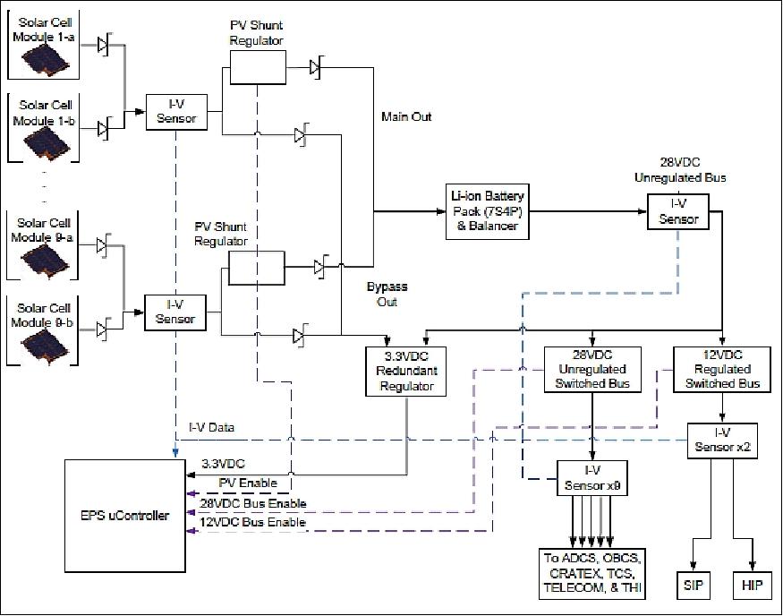
EPS
The spacecraft generates 28 VDC unregulated current from the solar panels, which is used to charge the 28 VDC battery. The battery distributes 12 VDC to the HIP (HSFL Imager Payload) and SIP (Separation Imager Payload) instruments and an unregulated 28 VDC bus to the rest of the subsystems where the local power distribution unit regulates the voltage down to the required voltage of each subsystem (Figure 3).
The eight body-mounted solar array panels each consist of two solar array modules (strings) with 19 solar cells per module (Figure 20). The solar cells being used are BTJM (Best Triple Junction with Monolithic diode) GaAs solar cells of Emcore with an efficiency of 28%. The solar arrays generate a peak panel power of ~42 W, with average power over an orbit (with losses) of ~37.7 W. The average power margin over an orbit is ~10.7 W.
The lithium-ion battery cells of Panasonic (CGR18650) are mounted in a 7S4P (seven series, four parallel) configuration providing 246.9 Wh (8.8 Ah, 25.2 V). These batteries have been flight proven in the GeneSat-1 and PharmaSat missions.
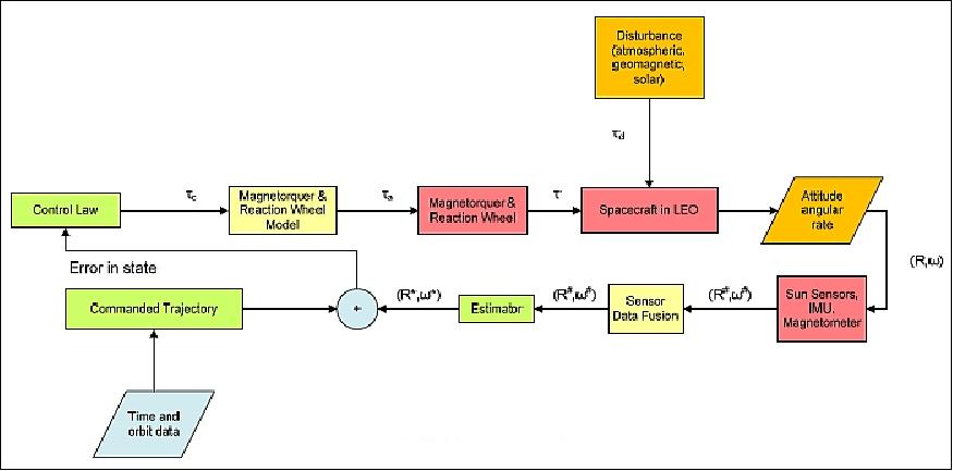
ADCS
The spacecraft is three-axis stabilized and capable of autonomous, closed-loop inertial pointing with an accuracy of ≤ 3º. Attitude measurement accuracy is adequate to determine where the spacecraft is pointing to 1-2º. This accuracy is achievable in real-time, in darkness or sunlight, and during all phases of the flight after deployment.
The ADCS provides the spacecraft with the capability of maintaining the +z face of the spacecraft pointing in a nadir (geocentric) direction with an accuracy of ±3º. This is the attitude required for the imaging payloads. Attitude data obtained from the spacecraft's ADCS sensors are autonomously processed aboard the spacecraft to determine spacecraft orientation. The attitude determination is accomplished using three space-qualified AeroAstro MSS-01 sun sensors, each with 60º full-angle circular FOV providing an accuracy of ~1º, and two Microstrain 3DM-GX2 inertial measurement units (IMUs), each of which contains a 3-axis magnetometer, three accelerometers, and a rate gyroscope.
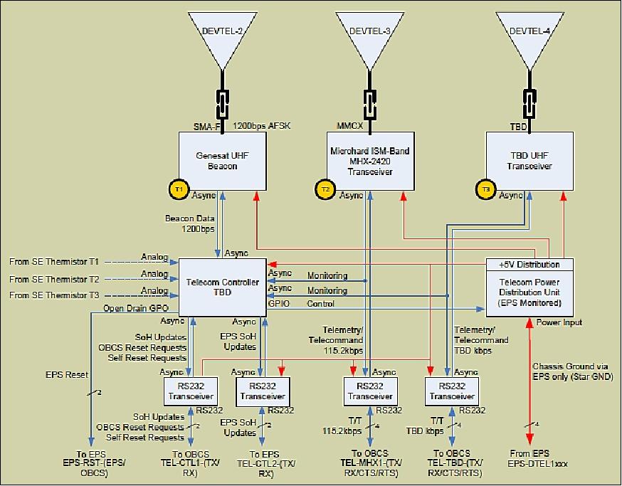
Telecommunications (telecom) subsystem
Communication is provided by S-band and UHF-band transceivers linked to a ground station located at the Kaua'i Community College (KCC) on the Hawaiian island of Kaua'i and other partner ground stations around the world.
The UHF radio system is of GeneSat-1 and PharmaSat satellite heritage. The UHF beacon provides amateur frequency beaconing with ASFK modulation. State of health information will be publicly available for the amateur community to decode and find out more about the satellite. It is one of the project goals to use this beacon in educational and community outreach events. The Microhard MHX-2420 is a newer version of the GeneSat MHX 2400 radio, and supports a data rate of 115.2 kbit/s. This system is designed as the primary command and telemetry radio. To keep interfaces simple, RS232 was chosen as the standard serial signaling between all telecom components.
The S-band downlink is used to transmit imagery to the ground. The radio is TBD. On onboard storage capability of 3 GB is provided.
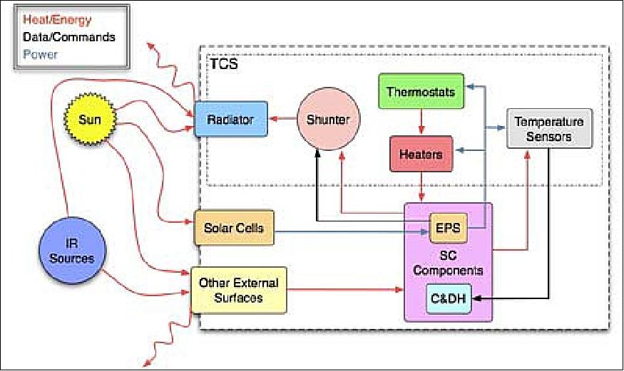
TCS (Thermal Control Subsystem)
The TCS is designed to ensure all spacecraft subsystem components are thermally controlled for operation, both in sunlight and eclipse periods. The TCS will also provide SOH temperature from all critical points of the spacecraft to the OBCS. Due to the fairly benign thermal environment of a low Earth orbit, passive thermal control was determined to be sufficient. The internal power dissipation required to be handled by the TCS is from a minimum of 2.6 W to a maximum of 96.2 W. The TCS hardware consists of MLI (Multi-Layer Insulation) blankets on the interior S/C panels, appropriate surface finishing (e.g., paints), three thermostats with redundancy, heaters for critical components and temperature sensors).
The A/D board that will collect the thermal data is capable of reading 32 single-ended inputs and is compatible with RTDs (Resistive Thermal Device) sensors making is possible to have a significant amount of thermal information from the various subsystems in the spacecraft. This information is passed to the OBCS for post processing and storage. The OBCS is capable of deciding if some power line for the heaters must be turned on or off in case of any failure from the thermostats or the EPS.
Spacecraft size | 64.7 cm diameter, 40.3 cm height |
Spacecraft mass | 55 kg |
Solar panels | 10 |
Payload mass, volume | 7.26 kg, 279 x 406 x 254 mm |
Launch
The HawaiiSat-1, as primary payload, was launched on November 4, 2015 (03:45:00 UTC) on the ORS-4 (Operationally Responsive Space-4) mission of DoD (USAF ORS office). A Super Strypi launch vehicle (LV) will deliver the HawaiiSat-1 payload and multiple secondary CubeSat payloads into orbit. The Super Strypi is a rocket developed by Sandia National Laboratories with assistance from the University of Hawaii, Aerojet and the U.S. Defense Department. The launch site is PMRF (Pacific Missile Range Facility) Barking Sands of the US Navy, located on the Hawaiian island of Kauai. 7) 8) 9) — Unfortunately, the Super Strypi launch vehicle experienced a launch failure about 1 minute into the flight. 10) 11)
Note: The original launch date was delayed from October 2013, to April and to October 2014. Then delayed again from January 2015 to January 2016. HawaiiSat-1 was delivered in August 2014 for integration with the LV (when an October launch was expected) and is currently in storage at Kirtland AFB waiting for launch. The LV was finally certified for flight in Q1 2015, but had missed the January launch window.
The HawaiiSat-1 microsatellite will be deployed from PAD (Payload Adapter and Deployer), being developed by NASA/ARC (Ames Research Center). The PAD will be capable of carrying one primary microsatellite and up to 24 or 32 CubeSats or equivalents.
Secondary Payloads
• Argus, a 2U CubeSat of SLU (Saint Louis University), Saint Louis, MO, and ISDE (Institute for Defense and Space Electronics) at Vanderbilt University (VU) in Nashville, Tennessee (2 kg). A collaborative nanosatellite radiation mission.
• EDSN (Edison Demonstration of Smallsat Networks). The EDSN mission of NASA/ARC (Ames Research Center) consists of a swarm of 8 1.5 U CubeSats, each with a mass of ~ 2kg. The EDSN project aims to demonstrate cross-satellite data communications for flexible data correlation and distribution as well as simplified satellite operations and data downlink. Being a constellation of satellites outfitted with space weather sensors, EDSN can deliver spatially and temporarily correlated data sets that can not be acquired from single satellite missions.
• PrintSat, a 1U CubeSat of MSU (Montana State University). PrintSat is a technology demonstration to assess the effectiveness of additive manufacturing (i.e. 3D printing) and the Windform XT material for use as a material for space structures. 12)
• Argus, a 2U CubeSat of St. Louis University and Vanderbilt University. Argus uses a platform named SCARAB and a research payload named Independence, which will be used to update models of how electronics behave when exposed to radiation in the space environment.
• STACEM, a 3U CubeSat designed, built and operated by the SDL (Space Dynamics Laboratory) of USU (Utah State University). The satellite demonstrates a miniaturized multi-spectral payload for the acquisition of imagery in the visible and near infrared wavelengths and hyperspectral channels. Imagery is to be used in environmental monitoring. The launch of STACEM on the SPARK launch vehicle is financed by the U.S. National Reconnaissance Office.
• Supernova-Beta, a 6U prototype CubeSat of Pumpkin Inc. Supernova is a satellite platform designed to be highly configurable for a rapid integration of enhanced CubeSat missions, offering a payload volume of 7000 cm3. The Supernova chassis has a mass of 1.64 kg and the total allowable mass of the satellite is specified as 12 kg by Pumpkin.
The NLAS (Nanosatellite Launch Adapter System) of NASA is manifested on the ORS-4 mission. The NLAS deployer includes adapter, 6U dispenser, and sequencer. The adaptor prototype design was provided by NASA/ARC, the final design, fabrication and test was provided by Moog CSA Engineering. A single NLAS provides the capability to deploy 24U of CubeSats. The system is designed to accommodate satellites measuring 1U, 1.5U, 2U, 3U and 6U sizes for deployment into orbit. 13) 14)
Orbit: Near-elliptical orbit, altitude of 430 x 505 km, inclination = 94.8º, period of ~ 90 minutes.
Sensor Complement
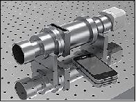
SUCHI (Space Ultra-compact Hyperspectral Imager)
SUCHI is a hosted scientific payload from HIGP (Hawai'i Institute of Geophysics and Planetology) of the University of Hawai'i at Manoa. SUCHI is based on a variable -gap Fabry-Perot interferometer employed as a FTIR (Fourier Transform Infrared) spectrometer providing a new UH technology (patent pending). The development to TRL 4 was funded by DARPA (Ref. 2).
SUCHI provides the following features: 15)
• Fabry-Perot FTIR
- New UH technology
- Patent pending
• Uncooled 320 x 256 microbolometer array
- FLIR Photon 320, a high-resolution infrared sensor in a small, light, and affordable package
- Sensitivity 20 mK or better at 30 Hz frame rates, F-number 1.4
- ~ 220 m ground resolution
- 7 spectral channels between 7 and 14 µm
• 4 calibration shutters
• Camera inside a pressure vessel
• SUCHI is a low volume (40 cm x 10 cm x 12.5 cm) and low mass (<9 kg) instrument, to conform to the volume, mass, and power requirements of the small satellite.
• The commercial microbolometer camera and vacuum-sensitive electronics are contained within a sealed vessel pressurized to 1 atm.
• The sensor will collect spectral radiance data in the long wave infrared region (7-14 µm) and demonstrate the potential of this instrument for advancing the geological sciences (e.g. mapping of major rock-forming minerals) as well as for volcanic hazard assessment (mapping volcanic ash, quantification of volcanic sulfur dioxide pollution and lava flow cooling rates).
The imager is designed to study geological phenomena like volcanic eruptions and lava flows, with a six-month primary mission that could be extended to two years. It will help geologists to monitor volcanic gas emissions and rates at which lava cools. The captured images are also expected to be useful in the mapping of major rock mineralogy.
SUCHI is a FTIR imager using new technology developed at UHM (University of Hawaii, Manoa). Light from the scene is focused onto the uncooled microbolometer array via a pair of multi-element refractive lenses (an objective and a relay). A Fabry-Perot interferometer (made of germanium) is located between these two lenses. An air gap of variable distance between the two pieces of germanium (i.e. the internal surfaces are sloped with respect to each other) causes multiple reflection/transmission of light rays from the scene, with rays that emerge having recombined with a phase shift that varies linearly across the optical axis. Thus, an interference pattern is recorded at the detector array. At a frame rate of 60 Hz, the forward motion of the satellite causes each scene element on the ground to be imaged at a different position in this interference pattern (i.e. with a different optical path difference). By georegistering such a sequence of frames, an interferogram for each point on the ground can be retrieved, and converted to a spectrum using standard Fourier transform techniques.
Four calibration shutters provide calibration. One pair of shutters (one can be heated; one floats at the ambient temperature of the instrument) are located at the instrument aperture and provide for instrument calibration from raw instrument counts to spectral radiance. Another identical pair of shutters is located between the relay optic and the detector array and is used to correct for array non-uniformity. Spectral calibration has been performed pre-flight, and will be confirmed on orbit using atmospheric absorption features. The ground resolution of the instrument is ~220 m, with a spectral sample of seven wave channels between 7 and 14 µm. The demonstration of the viability of this camera in space will enable its use in future HSFL and other Earth observation missions. Global scale measurements of the Earth from space for spectral reflectance and remittance have been limited by the spectral resolution of existing imaging sensors. SUCHI represents a low mass, low complexity solution to acquiring high spectral resolution remote sensing data in the long-wave infrared.
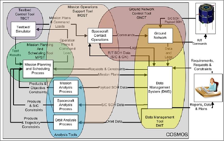
COSMOS (Comprehensive Open-architecture Space Mission Operations System)
HSFL (Hawaii Space Flight Laboratory), in collaboration with NASA/ARC (Ames Research Center) and Santa Clara University, are developing COSMOS to support this and future space missions. COSMOS features a set of software tools and hardware that is designed to primarily support the development and operations of one or more small spacecraft throughout the life cycle. COSMOS will be particularly suited for organizations with limited development and operations budget, such as universities.
The COSMOS system should be easily adaptable for adding spacecraft, interfacing with external software, and porting to MOCs (Mission Operations Centers) at HSFL, NASA/ARC, SCU (Santa Clara University) and other MOCs. 16) 17)
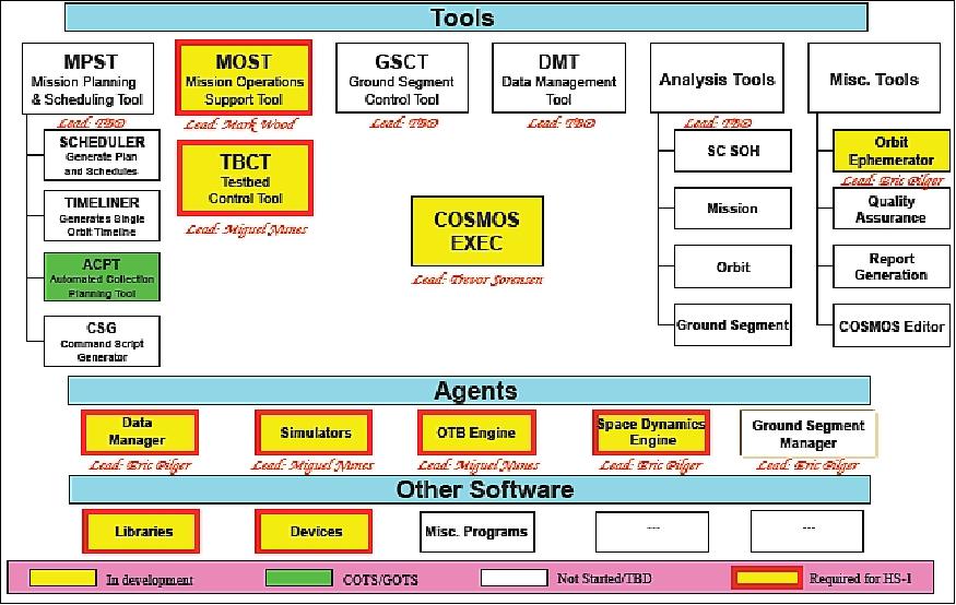
The COSMOS architecture provides a number of software tools to serve well defined operational roles and applications: 18) 19)
• MOST (Mission Operations Support Tool)
• MPST (Mission Planning & Scheduling Tool)
• GSCT (Ground Segment Control Tool)
• DMT (Data Management Tool)
• FDT (Flight Dynamics Tool)
• Analysis Tools
• TBCT (Test Bed Control Tool).
COSMOS is a suite of software and hardware tools that enables the operations team to interface with the spacecraft, ground control network, payload and other customers in order to perform mission operations functions. COSMOS is being designed to easily be adapted for new spacecraft or installation in new MOCs (Mission Operations Centers). Some of the basic elements of COSMOS have been developed at least to the prototype stage, while other elements are still in the conceptual stage. Although all the basic mission operations functions will be developed as part of COSMOS, it is also being designed to accept external modules (applications) as part of its "Plug-and-Play" architecture. 20) 21)
The COSMOS system will initially be installed in the HSFL and ARC MOCs and used in support of their small LEO satellites. However, the versatility of COSMOS is demonstrated in that it is being modified to support an international lunar mission in a Phase 0 study. The primary COSMOS mission monitoring and control tool, MOST, is being used for monitoring and controlling the spacecraft, lander, and lunar rover.
The importance of PPMO (Plug ‘n' Play Mission Operations)20)
The space community is currently witnessing a universal trend rolling through space segment architectures that can be easily visualized by the steady reduction of satellite size and mass coupled with a constant increase in space systems capabilities. This unique dynamic is due to a confluence of technological factors similar to and including Moore's Law. - Smaller spacecraft can process more data, perform more observations, and downlink more information due to continual, almost exponential advancements in computational power, solar cell efficiencies and energy storage technologies, advanced software applications, and the ability to inexpensively launch small spacecraft as secondary (or even tertiary) spacecraft on otherwise large, expensive launch vehicles.
In addition to the proliferation of these smaller, cheaper spacecraft, innovative space architectures are now also being seriously considered and even tested in space. These new architectures include cooperative, multi-spacecraft swarms or constellations that are theoretically capable of executing missions or collecting measurements and observations that are well outside of the traditional, single large spacecraft architecture and performance realms.
However, these exciting developments within the space segment are not without challenges. While the ability to reduce the size, weight and power of a spacecraft does indeed have direct cost implications, which are primarily manifested in the reduced cost of access to space, the space operations community must be prepared to support and operate these constellations or swarms of large numbers of small spacecraft in an equivalent low cost fashion. Simply scaling the traditional methods currently in use by many government or even commercial agencies would be prohibitively costly and would severely dilute the benefit of the low cost, small spacecraft platform. Therefore, similar revolutions invoking standard interfaces, high levels of automation, and other related technologies must be brought to bear on the ground segment part of the equation to fully realize the next generation of low cost, robotic spacecraft.
A fertile concept developed to stimulate this transformation is a philosophy loosely named PPMO (Plug-and-Play Mission Operations) where custom software and extensive testing can be significantly reduced or even eliminated, thus shortening development schedules, reducing overall mission risk and minimizing costs associated with the deployment and utilization of potentially many, many small spacecraft performing many diverse functions.
COSMOS Architecture and Design
The central pieces of this architecture are the visualization tools, support tools, and underlying programs that produce and manipulate the data needed by the rest of the tool sets. It combines both the software and unique hardware needed to support mission operations, including an OTB (Operations Test Bed) and simulators. The simulators are all software applications, and the OTB combines simulators with spacecraft hardware where possible to mimic as closely as possible the reaction of the spacecraft to commands and operational states.
The basic philosophy behind the construction of this architecture is that its elements (tools and other programs) will be easy to port to a new location and to modify for operating with new satellites. This is enabled by being an "open architecture." This approach means not only that the source code of its major elements and structure are available, but also that it is designed to accept external modules (which may not have source code available) as plug-ins through standard, well-defined interfaces in order to increase the overall capability of COSMOS for the desired application. - However, it is recognized that there could be ITAR (International Traffic in Arms Regulation) issues with COSMOS since it is designed to help control satellites. Therefore, a more limited definition of "open architecture" is used than the common one of having the source code in the public domain. Distribution of the COSMOS source code can be limited to only those entities (US government agencies, companies, or universities) which are allowable within ITAR restrictions. Hopefully, in the future this restriction can be relaxed as the ITAR restrictions are redefined or COSMOS is determined to not be an export-controlled product.
COSMOS is a suite of software and hardware tools that enables the MOT (Mission Operations Team) to interface with the spacecraft, ground control network, payload and other customers in order to perform the mission operations function. The basic COSMOS functional architecture is shown in Figure 12. Within COSMOS the following major functions are performed/supported: mission scheduling; contact operations; data management, mission analysis; simulations (including the OTB); ground network monitoring and control; payload operations, flight dynamics (including orbital and attitude); and support of system management and quality assurance. The description given here is for a full implementation of COSMOS to support flight operations, but some of the features may not be required by a particular MOC or mission.
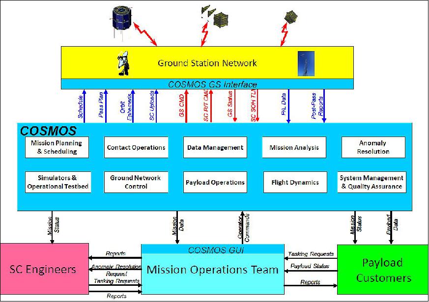
A computer is typically placed at each mission ground station to provide the interface between COSMOS and the ground station for data management (both to and from the ground station), and to monitor and possibly control the operations of the ground station. The various tools of COSMOS provide the graphical interface between the MOT and the COSMOS functions. The MOT communicates with spacecraft engineers to assist in SOH (State-of-Health) matters, such as anomaly resolution, and reports of the condition of the spacecraft and receives in return any constraints or tasking that may be required. The MOT also communicates with the various payload customers to receive reports on the status of the instruments and mission accomplishment goals, as well as to receive payload tasking requests. COSMOS uses websites or other means to allow the spacecraft engineers and customers to monitor the status of the mission directly without having to go through the MOT.
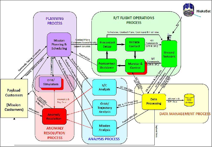
The functional flow block diagram of COSMOS is shown in Figure 13 . There are four major processes in mission operations that are supported by COSMOS:
1) Mission Planning and Analysis, which also includes command sequencing and the simulators and operations testbed
2) Contact Operations, which includes pre-contact operations, real-time contact operations, and post-contact operations both in the MOC and the ground network
3) Data Management, which includes transfer of all data throughout COSMOS and between COSMOS external locations; data processing, such as engineering units conversion and Level 0 data processing; and data archiving
4) Mission Analysis, which includes support by the MOT to analyze and trend spacecraft and ground network SOH data, orbital and trajectory data, and mission accomplishment data to help determine the mission success MOE s(Measures of Effectiveness). The results of the Mission Analysis process are fed back to the mission planners, spacecraft engineers (especially for resolving spacecraft anomalies), mission management, and customers.
COSMOS Tools
The tools of COSMOS are the software applications with which the human operators interact to control COSMOS and the mission operations processes.
CE (COSMOS Executive): There needs to be a way to monitor and control the operation of the entire COSMOS system and possible to launch or terminate various COSMOS tools. The CE fulfills this function. It shows which elements of COSMOS are running, which mission/spacecraft they are controlling, their current status and level of activity. From the CE you can start up any of the COSMOS tools and transfer into that tool if desired as a new computer session, which will put the CE into background mode, possibly within a separate window if desired. The CE also provides another function – it is the way to monitor multiple satellites and ground stations simultaneously from a single tool.
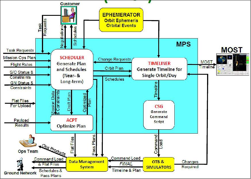
MPST (Mission Planning and Scheduling Tool): The MPST converts mission status and tasking inputs into executable command loads or sequences, schedules, and timelines. The MPST provides a top-level interface to the mission planner (human) and consists of the following major tools: Scheduler (produces the long- and short-term plans and schedules), Timeliner (produces the timeline), and Command Script Generator (produces the command script or sequence that is uploaded to the spacecraft). An example of the application of the "Plug-and-Play" paradigm in COSMOS is the inclusion of the independent mission planning module, developed by Riverside Research, called the ACPT (Automated Collection Planning Tool). This tool is built on AGI's STK engine and is being used for the DoD's MTI (Multispectral Thermal Imaging), TacSat-3, and other missions. This optional module provides a powerful addition to the MPST to help plan remote sensing missions while considering constraints, criteria, priorities, and resource utilization.
OTB (Operations Test Bed) and Simulators: The COSMOS OTB uses an open-source system architecture that integrates hardware and software components and tools to operate a low cost Satellite System Simulator (e.g. FlatSat) which can be integrated into the MOC setup for command scripting testing, personnel training, mission rehearsals and anomaly resolution. The OTB has tools for satellite technology integration and development that allows for cheaper satellite subsystem integration and testing. The OTB tools are based on COTS that are affordable to universities while some tools are being developed under the COSMOS project using proven standards and made available to the small sat community. The OTB is part of the four major processes in mission operations that are supported by COSMOS, namely the Mission Planning and Scheduling, Real-time contact operations, mission analysis, and anomaly resolution.
MOST (Mission Operations Support Tool): This is the primary element of COSMOS and is the visualization tool designed specifically for supporting real-time operations. However, MOST can also be used for supporting the following major operations functions:
1) spacecraft & payload monitor & control
2) mission planning
3) simulations & rehearsals
4) trending & analysis
5) anomaly resolution.
MOST is based on the LUNOPS program that was developed to support both LEO and lunar operations for the Clementine mission in 1994. Features of LUNOPS were incorporated into the design of some JPL mission operations software.
GSCT (Ground Segment Control Tool): This is a graphical interface for monitoring and controlling the ground network. GSCT includes all the pertinent information of each ground station, such as location, antenna type, contact information as well as a status for the ground station. The GSCT displays the ground station configuration for an upcoming contact (e.g., which files are waiting for upload, frequency setting, ephemeris file used for open-loop tracking). It also allows monitoring of the ground station status during a contact, displaying the antenna pointing angles, actual versus predicted antenna pointing, carrier signal detection and lock status, signal strength and data rate, etc. GSCT also allows the user in the MOC to send commands to the ground station as required. The GSCT is designed to view the ground segment/network data in a manner that allows the user to understand the information quickly and easily. It is possible to view all of the ground stations on a map with their statuses easily discernable. The input to GSCT comes from users, MOST and the customers. The output goes to the customers and the DMS (Data Management System).
DMT (Data Management Tool): Files are the primary method of data flow between elements of COSMOS. Central storage and dissemination of the files is through a DMS whose function is to:
• Accept files for delivery to other parts of the system
• Store files for long term access
• Provide access to stored files
• Forward files to other parts of the system.
The DMS will be able to manage multiple spacecraft, distinguishing between them by spacecraft designator. It stores both informational data, and longitudinal data, such as payload data and telemetry. Longitudinal data are accessible by date of creation. The DMS is split between a DMA (Data Management Agent), and a DMT (Data Management Tool). The DMA stores files in a simple directory structure, receiving them via standard file transfer protocols. These files are available either through the local file system, in the case of the MOC, or through standard file transfer protocols. Control of the DMA is through a GUI-based control program, the DMT. The DMT allows monitoring and control of the DMA, as well as adding additional features for analyzing data storage and flow.
Ground Segment
The spacecraft will be operated at the MOC (Mission Control Center) located at HSFL The MOC uses the internet for ground station connectivity. MOC schedules all spacecraft tracking services with the ground network.
The HSFL ground station network will utilize assets at ASF (Alaska Satellite Facility), Kauai Community College (HI), and Santa Clara University (CA) for satellite data download and command and control:
• Alaska Satellite Facility S-band data downlink and command and control uplink
• Kauai Community College UHF data downlink and command and control uplink
• Santa Clara University S-band data downlink and command and control uplink and UHF uplink and downlink.
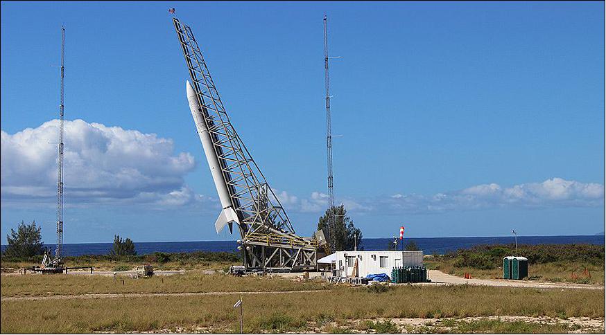
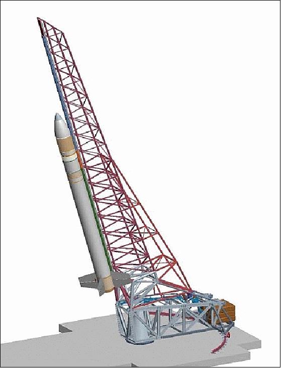
ORS-4 (Operationally Responsive Space-4) / Super Strypi Mission
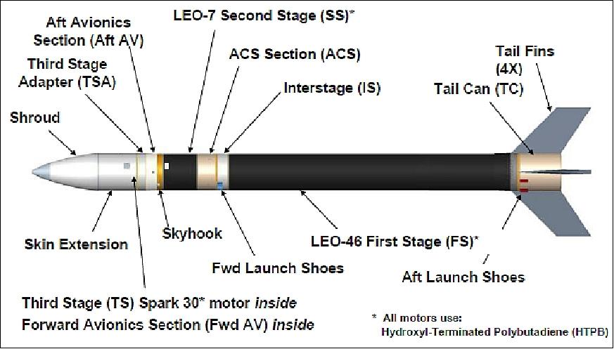
The ORS Office with support from the SNL (Sandia National Laboratories) is developing a small launch vehicle known as Super Strypi. The goal is to deliver payloads in the range of 300 kg to LEO (Low Earth Orbit). This effort includes the development of three new solid rocket motors from the venerable rocket motor and engine provider Aerojet.
The University of Hawaii's HawaiiSat-1 microsatellite will fly as the primary payload on the Integrated Payload Stack with an additional 13 CubeSats flying as secondary payloads. Super Strypi is unique in that it is spin stabilized throughout the entire flight. This sounding rocket approach keeps the system as simple as possible and eliminates the significant amount of engineering hours required on guided rockets to develop control algorithms and testing. 22) 23) 24)
Major objectives include demonstration of an alternative launch vehicle concept that reduces total mission cost through simple and repeatable process, moving launch vehicle processing from heavy reliance on engineering hours to technician hours, and reducing launch vehicle integration and processing timelines, contributing to responsive and lower cost launches. 25)
The ORS-4 mission is sponsored by the ORS Office and is the first launch of the Super Strypi launch system. The ORS-4 mission will complete the Super Strypi launch system design, install a launcher rail and pad at the Navy Pacific Missile Range Facility (Kauai, Hawai'i), and demonstrate launch system including launch to LEO (Low Earth Orbit), currently planned for 2014. Long term Super Strypi objectives are to develop a launch system to exploit the 21st century range with a reduced infrastructure - AFSS (Autonomous Flight Safety System), GPS metric tracking, spaceborne telemetry relay, automated flight planning. 26)
For Hawai'i's first space launch, the UH /HSFL (University of Hawaii/ Hawaii Space Flight Lab) is the contractor for the launch facility. The three rocket motor stages are designed and built by Aerojet.
The ORS-4 launch vehicle will also carry an AFSS (Autonomous Flight Safety System) unit that integrates GPS, an IMU (Inertial Measurement Unit) and algorithms to track the rocket's path. The first successful AFSS function test was conducted with the ORS-3 launch on Nov. 20, 2013 from MARS MARS (Mid-Atlantic Regional Spaceport) on Wallops Island, VA on a Minotaur-1 vehicle of OSC (Orbital Sciences Corporation.
The spin-stabilized, rail-launched Super Strypi launcher is capable of placing as much as 300 kg of payload into EO (Low Earth Orbit). The ORS Office hopes the new launcher, essentially a souped-up sounding rocket, will provide a low-cost launch option for small satellites, including CubeSats, which are becoming increasingly popular with universities and government agencies. U.S. defense organizations including the Army, the Air Force and even the National Reconnaissance Office, which is known for building billion-dollar satellites that launch on heavy-lift rockets, have been investing in CubeSats in recent years. Aerojet Rocketdyne is supplying the Super Strypi rocket's three rocket motors. 27)
Operationally Responsive Space Office, other Government and industry officials hope the Super Strypi has applications in the commercial industry as a dedicated small satellite launcher. The Air Force estimates the Super Strypi launch system will cost about $15 million per flight once in production, with a goal of cutting the unit cost to $12 million.
References
1) Information provided by Trevor C. Sorensen of HU/HSFL.
2) "Hawaii Space Flight Laboratory Overview," October 10, 2013, URL: http://www.hsfl.hawaii.edu/wp-content/uploads/2013/10/HSFL_Overview_101013.pdf
3) Luke Flinn, Lloyd French, Leonard Gouveia, "Hawaii Space Flight Laboratory," July 19, 2010, URL: https://web.archive.org/web/20111024031315/http://hsfl.hawaii.edu/HSFL_Overview_071910.pdf
4) Trevor C. Sorensen, Lloyd French, Jeremy K. Chan, William K. Doi, Elizabeth D. Gregory, Marcelo H. Kobyashi, "Hawai'iSat-1: Development Of A University Microsatellite For Testing a Thermal Hyperspectral Imager," AIAA Space Conference & Exposition 2010, Anaheim, CA, USA, Sept. 27-30, 2010, paper: AIAA-2010-8922
5) https://web.archive.org/web/20131104223430/https://www.hsfl.hawaii.edu/wordpress/missions-2/hawaiisat-1/
6) "University of Hawaii Role in ORS-4 Mission, Super Strypi – Responsive Small Launch," US Space and Missile Defense Symposium, August 11-14, 2013, URL: https://web.archive.org/web/20161010175508/http://smdsymposium.org/wp-content/uploads/2013/09/Super-Strypi-Kaufman-presentation1.pdf
7) Stephen Clark, "Debut flight of rail-guided space launcher slips to October," Spaceflight Now, March 23, 2015, URL: http://spaceflightnow.com/2015/03/23/debut-flight-of-rail-guided-space-launcher-slips-to-october/
8) Mike Gruss, "Despite Uncertain Future, ORS Office Has Missions To Work On," Space News, April 28, 2014, URL: http://spacenews.com/40368military-space-quarterly-despite-uncertain-future-ors-office-has/
9) Doug Messier, "ORS, University of Hawaii Team Up on New Small Satellite Launcher," Jan. 26, 2013, URL: http://www.parabolicarc.com/2013/01/26/ors-university-of-hawaii-team-up-on-new-small-satellite-launcher/
10) Mike Gruss, "Rail-launched Super Strypi Rocket Packed with Cubesats Fails in Debut ," Space News, Nov. 4, 2015, URL: http://spacenews.com/rail-launched-super-strypi-rocket-packed-with-cubesats-fails-after-liftoff/
11) Patrick Blau, "Debut Launch of Super Strypi Rocket fails during First Stage Flight," Spaceflight 101, November 4, 2015, URL: http://spaceflight101.com/debut-flight-of-super-strypi-rocket/
12) https://web.archive.org/web/20221205214903/https://ssel.montana.edu/printsat.html
13) Joe Maly, "CubeSat Payload Accommodations and Propulsive Adapters," Proceedings of the 11th Annual CubeSat Developers' Workshop - The Edge of Exploration," San Luis Obispo, CA, USA, April 23-25, 2014, URL: http://www.cubesat.org/images/cubesat/presentations/DevelopersWorkshop2014
/Maly_CubeSat_Payload_Accommodations.pdf
14) "Nanosatellite Launch Adapter System (NLAS)," NASA, August 30, 2013, URL: http://www.nasa.gov/centers/ames/engineering/projects/nlas.html#.U3HimHaegZM
15) S. T. Crites, P. G. Lucey, R. Wright, J. Chan, H. Garbeil, K. A. Horton, Amber Imai, M. Wood, L. Yoneshige, "SUCHI: The Space Ultra-Compact Hyperspectral Imager for small satellites," Proceedings of SPIE, Vol. 8739, 'Sensors and Systems for Space Applications VI,' 873902,May 21, 2013; doi:10.1117/12.2015628, Baltimore, MD, USA, April 29, 2013, URL of abstract: http://proceedings.spiedigitallibrary.org/proceeding.aspx?articleid=1690932
16) Trevor C. Sorensen, Eric J. Pilger, Mark S. Wood, Miguel A. Nunes, Bruce Yost, "A University-developed Comprehensive Open-architecture Space Mission Operations System (COSMOS) to Operate Multiple Space Vehicles," Proceedings of SpaceOps 2012, The 12th International Conference on Space Operations, Stockholm, Sweden, June 11-15, 2012, URL: http://www.spaceops2012.org/proceedings/documents/id1296468-Paper-001.pdf
17) Trevor C. Sorensen, Eric J. Pilger, Mark S. Wood, Miguel A. Nunes, "Implementing the Comprehensive Open-architecture Space Mission Operations System (COSMOS) to Operate Multiple CubeSats," Proceedings of the 11th Annual CubeSat Developers' Workshop - The Edge of Exploration," San Luis Obispo, CA, USA, April 23-25, 2014, URL: http://www.cubesat.org/images/cubesat/presentations/DevelopersWorkshop2014/Sorensen
_COSMOS.pdf
18) Trevor C. Sorensen , Eric J. Pilger, Mark S. Wood, Miguel A. Nunes, "Comprehensive Open-architecture Space Mission Operations System (COSMOS), Overview," PPMO (Plug and Play Mission Operations) Workshop, San Jose, CA, USA, May 16-17, 2011, URL: http://ppmo.arc.nasa.gov/media/Nunes-1.pdf
19) Trevor C. Sorensen, Eric J. Pilger, Mark S. Wood, Elizabeth D. Gregory, Miguel A. Nunes, "Development Of The Mission Operations Support Tool (MOST)," SpaceOps 2010 Conference, Huntsville, AL, USA, April 25-30, 2010, URL: http://www.hsfl.hawaii.edu/wp-content/uploads/2013/10/AIAA-2010-2230-245.pdf
20) Trevor Sorensen, Bruce Yost, Joan Differding, Eric Pilger, Miguel Nunes, "Plug and Play Mission Operations," Proceedings of the 2012 IEEE Aerospace Conference, Big Sky, Montana, USA, March 3-10, 2012
21) Trevor C. Sorensen, Jeremy K. Chan, Luke P. Flynn, Miguel A. Nunes, Eric J. Pilger, Robert Wright, Lance K. Yoneshige, "The COSMOS Mission Operations System and its Application to the HawaiiSat-1 Mission to Test New Remote Sensing Technologies," 10th IAA Symposium on Small Satellites for Earth Observation, Berlin, Germany, April 20-24, 2015, paper: IAA-B10-0204, URL of presentation: http://www.dlr.de/iaa.symp/Portaldata/49/Resources/dokumente/archiv10/pdf/0204_Sorensen.pdf
22) "Operationally Responsive Space–4," ORS, 2012, URL: http://ors.csd.disa.mil/media/ORS-4-final-Aug-2012.pdf
23) Peter Wegner, "ORS Program Status," Reinventing Space Conference, El Segundo, CA, USA, May 7-10, 2012, URL: https://web.archive.org/web/20150423114038/http://www.responsivespace.com/Papers/RS2012/SPECIAL%20SPEAKERS/Dr.%20Peter%20Wegner/Dr.%20Peter%20Wegner.pdf
24) Doug Messier, "ORS, University of Hawaii Team Up on New Small Satellite Launcher," Jan. 26, 2013, URL: http://www.parabolicarc.com/2013/01/26/ors-university-of-hawaii-team-up-on-new-small-satellite-launcher/
25) Keli Abe Trifonovitch, "Milestone for Hawaii's First Space Launch Completed In New Mexico," Oct. 28, 2013, URL: http://www.hawaii.edu/news/article.php?aId=6086
26) Thomas M. Davis; Thomas Atwood, Valerie Skarupa, John Puffenbarger, "Operationally Responsive Space: Assured Space Power Focused On Timely Satisfaction of Joint Force Commander Needs," Proceedings of the 9th IAA Symposium on Small Satellites for Earth Observation, Berlin, Germany, April 8-12, 2013, paper: IAA-B9-1004
27) Thomas M. Davis, "Operationally Responsive Space – The Way Forward," Proceedings of the 29th Annual AIAA/USU Conference on Small Satellites, Logan, Utah, USA, August 8-13, 2015, paper: SSC15-VII-4, URL: http://digitalcommons.usu.edu/cgi/viewcontent.cgi?article=3213&context=smallsat
The information compiled and edited in this article was provided by Herbert J. Kramer from his documentation of: "Observation of the Earth and Its Environment: Survey of Missions and Sensors" (Springer Verlag) as well as many other sources after the publication of the 4th edition in 2002. - Comments and corrections to this article are always welcome for further updates (eoportal@symbios.space).
Overview Spacecraft Launch Sensor Complement Ground Segment ORS-4 References Back to top