ORS Tech 1 and 2
Non-EO
Quick facts
Overview
| Mission type | Non-EO |
| Launch date | 20 Nov 2013 |
ORS Tech 1 and ORS Tech 2 / MBD (Multimission Bus Demonstration)
Overview Spacecraft Launch Mission Status Sensor Complement References
MBD (Multimission Bus Demonstration) is a prototype nanosatellite implementation of JHU/APL (Johns Hopkins University/Applied Physics Laboratory) in Laurel, MD, USA. The overall objective of this demonstration mission is to create a flexible and modular MMN (Multi-Mission Nanosatellite) spacecraft architecture that will allow low-cost execution of critical missions. 1) 2) 3) 4)
As a consequence of the university-level successes with establishing secondary launch opportunities and demonstrating the potential for CubeSats, multiple government organizations, including NASA, NSF (National Science Foundation), NRO (National Reconnaissance Office), the Army Space Missile Defense Command, and the Air Force Space Missile Center, are now engaged in their own CubeSat programs, with varying science and technology objectives. Their focus has shifted from a learning exercise to executing meaningful missions that capitalize on the attractive low cost and comparatively short development schedule (typically 12–18 months) for CubeSats. 5)
JHU/APL has been active for the past several years, promoting novel nanosatellite-class solutions to sponsor mission needs in space weather and space situational awareness, in addition to several nanosatellite subsystem component development efforts. The MMN (Multi-Mission Nanosat) architecture was created after carefully considering the requirements and their implications for a broad set of high-priority missions; the intricate technical details associated with engineering a flexible, scalable platform; and the issue of quality management to ensure successful missions. Moreover, it was developed with the goal that it could become an open, nonproprietary standard broadly used by the developer community.
Among the many enabled applications, JHU/APL has been conceptually exploring the means by which key space weather phenomena could be observed with greater spatial and temporal distribution using nanosatellites. To support this broad endeavor, JHU/APL has developed an initial triple (3U) CubeSat hardware prototype under a pathfinder effort, with two flight units, planned for launch in 2013. 6)
Renaming of the mission: The two MBD nanosatellites, representing a new capability for the military and intelligence and science communities, were renamed to ORS Tech 1 and ORS Tech 2 by the ORS (Operationally Responsive Space) Office of DoD. 7) 8)
Spacecraft
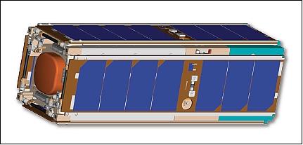
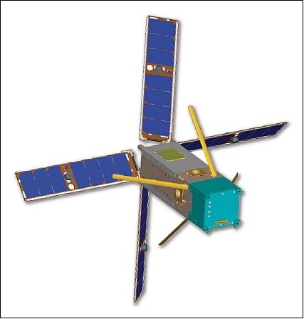
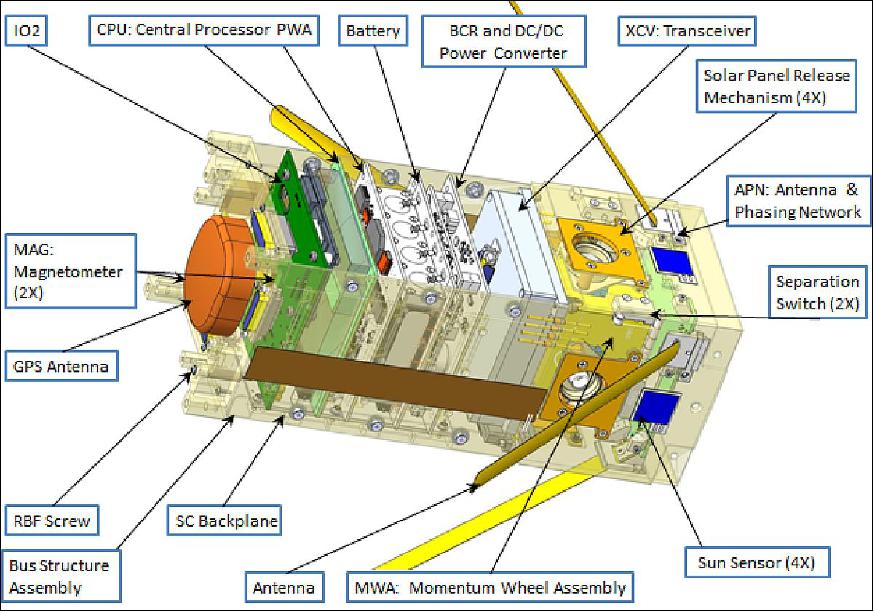
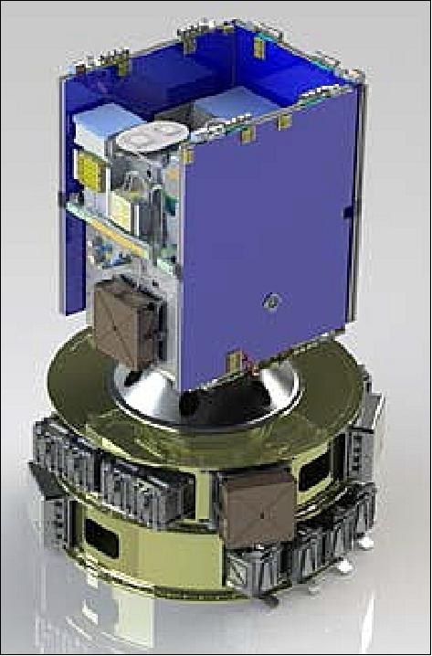
The pathfinder mission is using a standard 3U CubeSat form factor architecture with a size of 10 cm x 10 cm x 34 cm and a mass of < 5 kg. The modular design uses a flexible motherboard–daughterboard architecture, in which the individual printed wiring assemblies plug into a backplane. The backplane provides the board-to-board interconnects, eliminating much of the internal bus wiring harness. The deployed spacecraft configuration is shown in Figure 2 with the available payload volume in turquoise. 9)
ADCS (Attitude Determination and Control Subsystem): The ADCS features a 3-axis momentum-biased configuration, utilizing a combination of a single pitch wheel and four torque coils. The attitude knowledge is derived through a combination of sun sensors and a magnetometer.
EPS (Electrical Power Subsystem): In the MMN-3U configuration, a set of four double-sided, deployed solar arrays are oriented such that there is no spacecraft orientation in which energy generation is not possible. Across all sun-orbit beta angles, the system is capable of generating greater than 6 W of orbit average power. To maximize electric power transfer between the solar cell strings and the lower-voltage spacecraft power bus (battery), a peak-power-tracking power converter, developed particularly for nanosatellites, is used. Several DC–DC converters produce regulated bus voltages for use by the spacecraft and payload. A high-capacity lithium ion battery supports mission operations that require as much as 50 W peak power for durations up to 10 min per orbit, including during eclipse. Coupled with the high-peak-power capability, the thermal design can reject the heat, reflecting a detailed analysis of the conductive paths, radiated behaviors, and operational modes that drive thermal rejection performance.
In the MMN-3U design, the spacecraft is cold biased, with thermal coatings used to configure the exact operating temperature range for a specific mission. Make-up heaters are also incorporated to protect critical components, such as the battery.
For the solar panel deployment, engineers had to invent solar-panel release mechanisms that didn't include pyrotechnics, since microsatellites, as secondary or "piggy back" payloads on other launches, aren't permitted to carry explosives. Once deployed, the solar panels themselves have three jobs. Besides supplying power, they act as reflectors for the satellite's antennas, and the magnetic field produced from the internal torque coils are used to align the spacecraft.
C&DH (Command and Data Handling) subsystem: To provide scalable processing capability for the MMN command and data handling subsystem, a radiation-hard Aeroflex 32 bit LEON 3-FT processor is used. This processor is central to a joint development effort serving several APL Earth-orbiting, lunar, and interplanetary missions, extending its application to nanosatellites. The LEON processor-based avionics, with its associated circuitry, is capable of extended operation under extremely stressing radiation, both total ionizing dose and single-event upsets and latchups, and environmental conditions.
Real-Time Operation System & Flight Software: Free, open-source RTEMS (Real-Time Executive for Multiprocessor Systems) was selected for the RTOS (Real-time Operating System) and compatibility with the LEON3-FT processor. An OSAL (Operating System Abstraction Layer) was able to facilitate the development process through compatibility with existing tools, as well as leverage some heritage code previously developed at JHU/APL for the NASA STEREO mission (Ref. 6).
The flight software can execute time-tagged commands uploaded from the ground, as well as complex command sequences, for spacecraft and payload operations. In addition to collecting, processing, and storing all spacecraft state of health, sensor measurements, and payload data, the flight software also formats and interprets data communications on the telemetry and command link, including associated CCSDS (Consultative Committee for Space Data Systems) protocols, command extraction, and 128-bit (with option for 256-bit) AES (Advanced Encryption Standard) data encryption/decryption for all command and control links with the ground.
EMICE (Electromagnetic Interference-Controlled Environment): Many missions require very low interference and noise levels within certain frequency bands. Spacecraft have many potential noise and interference sources, such as DC–DC converters, computer clocks, processor buses, and radios, which can create both narrowband and broadband interference. Including electromagnetic interference control measures in the spacecraft design from the beginning, such as component shielding, interface signal filtering, and other proven design practices, is critical to avoiding costly corrective repairs during integration. The MMN structure has been designed as an integrated solution for electromagnetic interference shielding, thermal conduction, and radiation total ionizing dosage mitigation, with separate isolated cavities for bus and payload using five-sided "bathtubs" with labyrinth-seal covers, and filtered connectors for interfaces through the enclosure walls.
Mobile Antenna Ground Station: The MMN command and control approach can close the space-to-ground communications links with a simple, non-steering antenna, obviating the need for complex, high-gain antennas and positioners and enabling mobile operations in potentially disadvantaged conditions. As part of the prototype effort, APL is developing a portable ground terminal for spacecraft command and control and payload operations. The terminal bundles a communications transceiver into a briefcase-sized, fully functional command console capable of task planning, contact scheduling, scripting, and orbit prediction for constellations. The design highly leverages a parallel development effort supporting the NASA RBSP (Radiation Belt Storm Probes) program, APL's Mission Independent Ground System, and joint product development effort between APL and L3 Communications. The ground software command and control solution has been baselined for all APL missions currently in development.
Launch
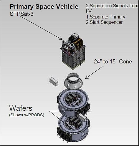
The ORS Tech 1 and ORS Tech 2 nanosatellites were launched on November 20, 2013 (01:15:00 UTC) from the MARS (Mid-Atlantic Regional Spaceport) on Wallops Island, VA on a Minotaur-1 vehicle of OSC (Orbital Sciences Corporation). The launch was part of the ORS-3 (Operationally Responsive Space-3) enabler launch mission. The primary payload on the ORS-3 mission was STPSat-3. 10) 11) 12)
ORS-3 is ushering in launch and range processes of the future. The ORS-3 mission will demonstrate and validate a new launch vehicle flight safety architecture of the future through the AFSS (Autonomous Flight Safety System) payload, which uses launch vehicle orbital targeting and range safety planning processes to protect public safety from an errant launch vehicle during flight. 13) The outcome of this test is of great interest to the military as well as to NASA. The launch also will be part of the Federal Aviation Administration's (FAA) certification process for the Minotaur rocket. The FAA has licensing authority over American commercial rockets.
Orbit: Near-circular orbit, altitude = 500 km, inclination = 40.5º.
Secondary Payloads: The secondary technology payloads on this flight consist of 26 experiments comprised of free-flying systems and non-separating components (2 experiments). ORS-3 will employ CubeSat wafer adapters, which enable secondary payloads to take advantage of excess lift capacity unavailable to the primary trial. 14) 15)
NASA's LSP (Launch Services Program) ELaNa-4 (Educational Launch of Nanosatellite-4) will launch eight more educational CubeSat missions. The ELaNa-4 CubeSats were originally manifest on the Falcon-9 CRS-2 flight. When NASA received word that the P-PODs on CRS-2 needed to be de-manifested, LSP immediately started looking for other opportunities to launch this complement of CubeSats as soon as possible. 16)
Spacecraft | ORS-3 mission sponsor | Spacecraft provider | No of CubeSat Units |
ORS-1, ORSES (ORS Enabler Satellite) | ORS (US Army) | Miltec Corporation, Huntsville, AL | 3 |
ORS-2, ORS Tech 1 | ORS Office | JHU/APL, Laurel, MD | 3 |
ORS-3, ORS Tech 2 | ORS Office | JHU/APL | 3 |
Prometheus-1 | SOCOM (Special Operations Command) | LANL (Los Alamos National Laboratory) | 1 x 3 |
Prometheus-2 | SOCOM | LANL | 1 x 3 |
Prometheus-3 | SOCOM | LANL | 1 x 3 |
Prometheus-4 | SOCOM | LANL | 1 x 3 |
SENSE-A | STP (Space Test Program) | SMC/XR | 3 |
SENSE-B | STP | SMC/XR | 3 |
Firefly | NASA/NRO | NSF (National Science Foundation) | 3 |
STARE-B (HORUS) | NRO (National Reconnaissance Office) | Lawrence Livermore National Laboratory | 3 |
Black Knight-1 | NASA LSP/STP | US Military Academy, West Point, NY | 1 |
TetherSat | NASA LSP/STP | US Naval Academy, Annapolis, MD | 3 |
NPS-SCAT | NASA LSP/STP | Naval Postgraduate School, Monterey, CA | 1 |
Ho'ponopono | NASA LSP/STP | University of Hawaii, Manoa, HI | 3 |
COPPER | NASA LSP/STP | St Louis University, St. Louis, MO | 1 |
ChargerSat-1 | NASA LSP/STP | University of Alabama, Huntsville | 1 |
SPA‐1 Trailblazer | NASA LSP/STP | COSMIAC, University of New Mexico | 1 |
Vermont Lunar CubeSat | NASA LSP/STP | Vermont Technical College, Burlington, VT | 1 |
SwampSat | NASA LSP/STP | University of Florida, Gainsville, FL | 1 |
CAPE-2 | NASA LSP/STP | University of Louisiana, Lafayette, LA | 1 |
DragonSat-1 | NASA LSP/STP | Drexel University, Philadelphia, PA | 1 |
KYSat-2 | NASA LSP/STP | Kentucky Space, University of Kentucky | 1 |
PhoneSat-2.4 | NASA LSP/STP | NASA/ARC, Moffett Field, CA | 1 |
TJ3Sat (CubeSat) | NASA LSP/STP | Thomas Jefferson High School, Alexandria, VA | 1 |
ORS and CubeStack: 17)
• ORS (Operationally Responsive Space) partnered with NASA/ARC and AFRL to develop & produce the CubeStack
• Multi CubeSat adapter provides "Low Maintenance" tertiary canisterized ride capability
• ORS-3 Mission: Will fly 2 CubeStacks in November 2013. This represents the largest multi-mission launch using a Minotaur I launch vehicle (26 free flyers, 2 experiments).
The CubeStack adapter structure is a design by LoadPath and Moog CSA Engineering. 18)
Mission Status
• April 20, 2015: After 18 months in orbit — months longer than typical for spacecraft in their class — the twin ORS Tech 1 and 2 CubeSats recently completed their final trip into Earth's atmosphere. 19) The program was a success, with both satellites de-orbiting in April 2015.
- When atmospheric drag caught up to the spacecraft in late March and early April 2015, they had completed one of the longest operational periods ever for a CubeSat. While numerous CubeSats are launched each year, many function only for a few hours, and those without onboard propulsion systems typically reenter Earth's atmosphere within a year.
- "The long mission duration of ORS Tech-1 and -2 has been very rewarding for our team of engineers and scientists," said Ann Darrin, program manager at APL, which built and initially operated the satellites. "Reliability was one of our considerations when we designed the spacecraft; in order to be of operational use to our sponsor the mission lifetime had to be one year."
- Following launch, the twin spacecraft went through an evaluation phase to determine the best configuration and operational scheme for meeting their payload's objectives. The technology demonstration segment of the mission ended in June 2014, when APL handed command and control of the spacecraft and ground system to its DoD (Department of Defense) customer. ORS Tech-1 became unresponsive before the operational phase, but ORS Tech-2 performed well over the 10 month operational period until the spacecraft reentered Earth's atmosphere.
• Both systems were fully commissioned into nominal mode over the course of the first week, demonstrating strong power margins, benign thermal behavior, stable pointing, and dependable communications between the satellites and ground. As planned, the mission operations were transitioned to highly automated, near lights-out function in the early January 2014 timeframe. 20)
• Given the favorable proximity to JHU/APL of the NASA Wallops Flight Facility where the ORS-3 mission launched from, contact was successfully made with both vehicles on the first overflight pass of the Master Gateway at JHU/APL approximately 100 minutes after launch.
Sensor Complement
Given the inherent packaging challenges of the CubeSat form-factor, MBD employs a highly-integrated design approach to incorporate all the critical subsystems found within a typical large mission satellite, with the requisite functionality to support a wide variety of missions. Several of these elements can and/or will be leveraged for GEOScan. (Note: GEOScan is a sensor suite of hosted EO payloads to be flown on Iridium NEXT).
CTECS (Compact Total Electron Content Sensor)
GPS receiver: An integrated NovAtel OEMV-1G (Original Equipment Manufacturer Version-1st Generation) GPS receiver is utilized onboard to supply periodic measurement of position and velocity data necessary for deriving an ephemeris solution, as well as provide an accurate time reference for calibrating precision clocks and other payload electronics as required. In addition to these functions, for GEOScan, the physically equivalent OEMV-1DF would be considered as a means to conduct radio occultation experiments (Ref. 6).
Note: CTECS was first flown on the PSSCT-2 (PicoSat Solar Cell Testbed-2) mission of The Aerospace Corporation (launch on July 20, 2011 from the Space Shuttle STS-135 mission). 21)
• Hardware consists of NovAtel OEMV-2 receiver, custom designed antenna Low-noise-amplifier (LNA), cables
• Receiver: CTECS tracks the L1, L2, L2C signals.
The Impact of Change to the System
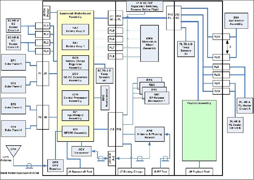
The sponsor of the proposed MBD (Multimission Bus Demonstration) nanosatellite, namely the ORS (Operationally Responsive Space) Office of DoD, required one change to be implemented on the MBD spacecraft bus in order to ensure compatibility with the sponsor's current ground system infrastructure. The proposed spacecraft was to replace the existing radio with the Vulcan Wireless CSR-SDR-U/U CubeSat Radio, to include the UHFSATCOM MIL-STD-188-181-B waveform. The Vulcan Wireless CSR-SDR-U/U CubeSat Radio is a Software Defined Radio working in the UHF (Ultra High Frequency) band. The transceiver is depicted within the spacecraft bus configuration in Figure 5. The transceiver is located well within the spacecraft, towards the middle of the configuration. 22)
As the proposed spacecraft bus was beginning the design phase, the heritage mission had just been launched. The two changes identified as in-flight experience from the MBD spacecraft were thus not identified until one to two months into the design of the proposed spacecraft bus. Therefore, of the three changes discussed herein, only one was known at the beginning of the design effort and only one was applicable to the proposed spacecraft bus.
The first change identified involved the additional power consumption from the GPS receiver to provide location coordinates to the spacecraft. The lesson learned was not implemented on the proposed spacecraft, but would have involved a simple modification to the spacecraft flight software code. The second change identified while the MBD spacecraft were in operation involved the malfunction of ORS Tech's antenna switch. Given the fact that the proposed payload no longer needed to share the antenna, there was no longer a need for the antenna switch in the new proposed system.
The replacement of the radio would be more of a challenge than implementing the heritage lessons learned on the proposed spacecraft. Figure 8 summarizes the changes that occurred throughout the space vehicle due to the need for a different radio.
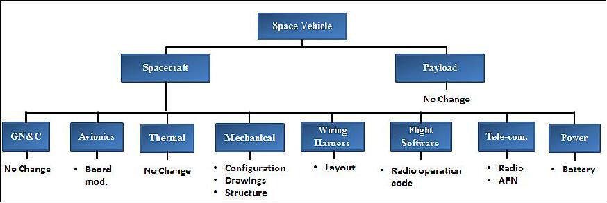
The Telecommunication subsystem bore the burden of a completely new radio with a new waveform. While the radio manufacturer was able to modify and meet the electrical hardware interface to the existing radio hardware interface, spacecraft flight software needed modifications for the spacecraft avionics to communicate with the new radio. Similar changes were required for the ground station software. The spacecraft radio required a RF bandpass filter to meet receiver performance specifications. This filter was added to the existing APN (Antenna and Phasing Network) design. It should be noted that the Vulcan radio operated differently from its predecessor when approaching a ground station as it remained in a constant beaconing mode. This may or may not be an issue for various payload missions. Since the sponsor requested radio was larger and thicker than the previous radio, the configuration layout required a re-arrangement of subsystem components. In order to accommodate the radio dimensions and maintain payload volume, the subsystem that faced a major change was the Electric Power subsystem (Power). Replacement of the heritage cells by commercially available battery cells having twice the capacity were identified and one battery card was eliminated. The Wiring Harness required minimum change; the layout had to be modified to account for the configuration change. A structure analysis to verify proper loads and mass properties and drawing updates to account for said changes.
The changes discussed above were those impacting the design and build of the flight hardware. A significant impact occurred in the later phases of the project lifecycle including the documentation for a transition to industry as well as the testing of the hardware. As JHU/APL is a non-profit University Affiliated Research Center (UARC), the organization specializes in novel and innovative builds and does not support mass production of technologies. In order to provide the sponsor with the ability to mass-produce the spacecraft bus or outsource the build and operation to another agency, the drawing package needed to be thorough and complete in its instructions. Each subsequent change to the spacecraft had to be re-documented in design as well as in test. Testing of the modifications was also necessary on the component level as well as on the system level given the number of affected subsystems.
The impact of change to the cost: According to Warfield and Roust (1998), the recommended cost to build a copy of an original unit is 36% of the cost of the first build. This percentage is based on recurring engineering versus non-recurring engineering where the 36% represents the recurring engineering. Whitley (2013) performed a cost analysis of JHU/APL-built spacecraft where a second copy was built and tested in parallel with the first spacecraft. The cost data supporting the analysis came from STEREO (Solar TErrestrial RElations Observatory) and Van Allen Probes, each mission flying two space vehicles with a mass of 500 to 700 kg. The average cost-to-copy percentage for these missions is 38%.
The MBD successor spacecraft bus was to be built at approximately 38% of the original unit. Given the significant non-recurring engineering changes needed to accommodate sponsor requirements, the team would have been hard pressed to meet the proposed cost. By the end of the re-design of the proposed spacecraft bus, the proposed spacecraft bus was projected to cost approximately the same if not more than the first MBD spacecraft unit. Thus, no cost savings were realized in the building of the successor version of the spacecraft bus. There were many reasons for this including no cost savings for integration and test, re-assessment costs to realize if re-design was necessary for each subsystem, the need to reiterate the drawing and documentation package, and the use of team members who were not part of the MBD team.
References
1) Aaron Q. Rogers, Robert A. Summers, "Creating Capable Nanosatellites for Critical Space Missions," JHU/APL Technical Digest, Volume 29, No 3, 2010, pp. 283-288, URL: http://www.jhuapl.edu/techdigest/TD/td2903/Rogers.pdf
2) Andrew A. Knuth, Philip M. Huang, Aaron Q. Rogers, "Multi Mission Bus Demonstration: A Unique Low-Cost Approach for End-to-End SensorSat Development," Reinventing Space Conference, Los Angeles, CA, USA, May 7-11, 2012
3) A. G. Darrin, P. M. Huang, A. A. Knuth, M. M. A. Anderson, "The role of SensorSats in Intelligence, Surveillance and Reconnaissance operations," Proceedings of the 2012 IEEE Aerospace Conference, Big Sky, Montana, USA, March 3-10, 2012
4) Aaron Q. Rogers, Larry J. Paxton, M. Ann Darrin, "Small Satellite Constellations for Measurements of the Near-Earth Space Environment," Proceedings of the 7th IAA Symposium on Small Satellites for Earth Observation, Berlin, Germany, May 4-7, 2009, paper: IAA-B7-1104
5) Ann G. Darrin, Andrew A. Knuth, Philip M. Huang, Matthew A. Anderson, "The Role of SensorSats in Intelligence, Surveillance and Reconnaissance Operations," Proceedings of the 2012 IEEE Aerospace Conference, Big Sky, Montana, USA, March 3-10, 2012
6) Lars P. Dyrud, Jonathan T. Fentzke, Gary Bust, Bob Erlandson, Brian Bauer, Aaron Q. Rogers, Warren Wiscombe, Brian Gunter, Shawn Murphy, Kerri Cahoy, Rebecca Bishop, Chad Fish, Om Gupta, "GEOScan: A GEOScience Facility From Space," Proceedings of the 26th Annual AIAA/USU Conference on Small Satellites, Logan, Utah, USA, August 13-16, 2012, paper: SSC12-IV-9, URL: http://digitalcommons.usu.edu/cgi/viewcontent.cgi?article=1043&context=smallsat
7) Michael Buckley, "Johns Hopkins Applied Physics Lab Launches New Generation of Small Satellites," JHU/APL, Nov. 19, 2013, URL: http://www.jhuapl.edu/newscenter/pressreleases/2013/131119.asp
8) "Experimental 'Cubesats' Designed for Range of National Security, Science Missions," Space Daily, Nov. 22, 20013, URL: http://www.spacedaily.com/reports/Experimental_Cubesats_Designed_for_Range_of-National_Security_Science_Missions_999.html
9) Philip M. Huang, Andrew A. Knuth, Margaret A. Garrison-Darrin, "Utilizing low-cost 3U single-sensor satellites for intelligence, surveillance, and reconnaissance mission capabilities", Proceedings of SPIE, Vol. 8385, 'Sensors and Systems for Space Applications V, 83850G,' Baltimore, MD, USA, April 23, 2012, doi:10.1117/12.919328
10) "Orbital Successfully Launches Minotaur I Rocket Supporting ORS-3 Mission for the U.S. Air Force," Orbital, Nov. 19, 2013, URL: http://www.orbital.com/NewsInfo/release.asp?prid=1876
11) Patrick Blau, "Minotaur I successfully launches STPSat-3 & record load of 28 CubeSats," Spaceflight 101, Nov. 20, 2013, URL: http://www.spaceflight101.com/minotaur-i-ors-3-launch-updates.html
12) Roz Brown, "Ball Aerospace's STPSat-3 to Fly Solar TIM Instrument for NOAA," BATC, July 19, 2012, URL: http://www.ballaerospace.com/page.jsp?page=30&id=478
13) Michael P. Kleiman, "ORS Office organizing three new programs," AFMC (Air Force Materiel Command), Aug. 30, 2012, URL: http://www.afmc.af.mil/news/story.asp?id=123316172
14) Peter Wegner, "ORS Program Status," Reinventing Space Conference, El Segundo, CA, USA, May 7-10, 2012, URL: https://web.archive.org/web/20150423114038/http://www.responsivespace.com/Papers/RS2012/SPECIAL%20SPEAKERS/Dr.%20Peter%20Wegner/Dr.%20Peter%20Wegner.pdf
15) Joe Maly, "ESPA CubeSat Accommodations and Qualification of 6U Mount (SUM)," 10th Annual CubeSat Developer's Workshop, Cal Poly State University, San Luis Obispo, CA, USA, April 24-25, 2013, URL: http://www.cubesat.org/images/stories/workshop_media/DevelopersWorkshop2013-Maly_MoogCSA_ESPA-SUM.pdf
16) Garrett Lee Skrobot, Roland Coelho, "ELaNa – Educational Launch of Nanosatellite Providing Routine RideShare Opportunities," Proceedings of the 26th Annual AIAA/USU Conference on Small Satellites, Logan, Utah, USA, August 13-16, 2012, paper: SSC12-V-5
17) "CubeStack: CubeSat Space Access," 9th Annual Spring CubeSat Developers' Workshop, Cal Poly State University, San Luis Obispo, CA, USA, April 18-20, 2012, URL: http://mstl.atl.calpoly.edu/~workshop/archive/2012/Spring/27-Maly-CubeStack.pdf
18) Joe Maly, "6U Mount for CubeSats on ESPA," CubeSat 9th Annual Summer Workshop, Logan UT, USA, August 11-12, 2012, URL: https://web.archive.org/web/20160914101344/http://mstl.atl.calpoly.edu/~bklofas/Presentations/SummerWorkshop2012/Maly_6U_ESPA_Mount.pdf
19) "ORS CubeSats Close Out a Successful Test," JHU/APL, April 20, 2015, URL: http://www.jhuapl.edu/newscenter/pressreleases/2015/150420.asp
20) Aaron Q. Rogers, Philip M. Huang, V. Edward Wells, M. Ann Darrin, Joseph J. Suter, "Small Satellite Initiates: Building on Success," Proceedings of the 30th Space Symposium, Technical Track, Colorado Springs, CO, USA, May 19-22, 2014, URL: http://spacesymposium.org/sites/default/files/downloads/A.Rogers_30th_Space-Symposium_Tech_Track.pdf
21) Rebecca Bishop, David Hinkley, Daniel Stoffel, David Ping, Paul Straus, Timothy Burbaker, "First Results From the GPS Compact Total Electron Content Sensor (CTECS) on the PSSCT-2 Nanosat," Proceedings of the 26th Annual AIAA/USU Conference on Small Satellites, Logan, Utah, USA, August 13-16, 2012, URL of the paper: http://digitalcommons.usu.edu/cgi/viewcontent.cgi?article=1088&context=smallsat URL of the presentation: http://digitalcommons.usu.edu/cgi/viewcontent.cgi?filename=0&article=1088&context=smallsat&type=additional
22) Lauren A. Mehr, Aaron Q. Rogers, "Only "one" small change needed: Lessons learned on an almost build-to-print nanosatellite," Proceedings of the 4S (Small Satellites, System & Services) Symposium, Valletta, Malta, May 30-June 3, 2016, URL: http://congrexprojects.com/docs/default-source/16a02_docs/4s2016_final_proceedings.zip?sfvrsn=2
The information compiled and edited in this article was provided by Herbert J. Kramer from his documentation of: "Observation of the Earth and Its Environment: Survey of Missions and Sensors" (Springer Verlag) as well as many other sources after the publication of the 4th edition in 2002. - Comments and corrections to this article are always welcome for further updates (herb.kramer@gmx.net).
Overview Spacecraft Launch Mission Status Sensor Complement References Back to top