PAZ SAR satellite mission of Spain
EO
Atmosphere
Land
Multi-purpose imagery (land)
Launched in February 2018 from Vandenberg Air Force Base in California, PAZ (‘peace’ in Spanish, previously known as Satélite Español de Observación SAR (SEOSAR)), is an X band Synthetic Aperture Radar mission of Spain. It is a dual-use mission, aimed at serving the security and defence needs of the Ministry of Defence. PAZ is managed by Hisdesat, a Spanish commercial company that provides its service to the Ministry of Defence, who funded and own the satellite.
Quick facts
Overview
| Mission type | EO |
| Agency | CDTI, INTA, HISDESAT |
| Mission status | Operational (extended) |
| Launch date | 22 Feb 2018 |
| Measurement domain | Atmosphere, Land |
| Measurement category | Multi-purpose imagery (land), Vegetation, Atmospheric Winds |
| Measurement detailed | Land surface imagery, Land cover, Oil spill cover |
| Instruments | Paz SAR-X |
| Instrument type | Imaging microwave radars |
| CEOS EO Handbook | See PAZ SAR satellite mission of Spain summary |
Related Resources
Summary
Mission Capabilities
PAZ carries the PAZ-SAR (Synthetic Aperture Radar) instrument that provides high quality SAR imagery in various swath widths and resolutions. PAZ-SAR uses an X-band active phased array antenna with an operation instantaneous bandwidth up to 300 MHz. The instrument offers features such as low profile, low mass, and flexibility of Beam Forming Network (BFM) topologies, as well as ease of manufacturing by providing good radiation efficiency. PAZ-SAR provides high resolution SAR images of Earth for governmental and commercial use as well as for ship tracking and weather sensing.
Performance Specifications
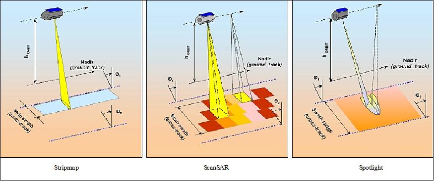
PAZ can operate in four imaging modes: Stripmap, ScanSAR, Spotlight and High Resolution Spotlight. The resolution and swath widths vary across the modes, with resolutions ranging from 1 - 15 m and swath widths ranging from 10 - 100 Km. PAZ’s goal is to provide more than 200 SAR images per day.
PAZ is in a sun-synchronous dawn-dusk orbit, at an altitude of 514 km and an inclination of 97.44°. The Local Time Ascending Node (LTAN) is at 1800 hours and the nominal revisit period is 11 days. It is positioned in the same orbit as the German-owned TerraSAR-X and TanDEM-X satellites to form a high-resolution SAR satellite constellation with them and decrease the revisit time to benefit various applications.
Space and Hardware Components
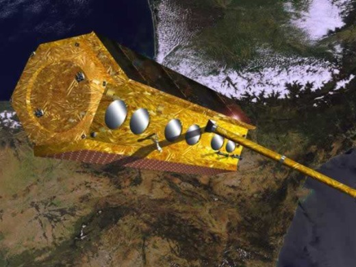
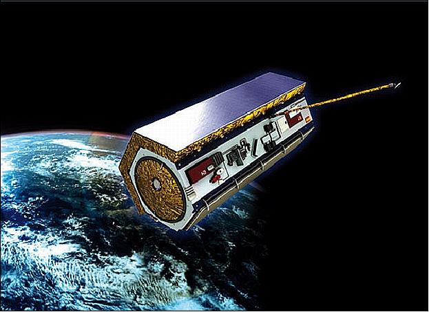
PAZ is built on a Service Module (SM) platform based on that of TerraSAR-X and TanDEM-X. The AstroBus platform is designed as a hexagonal shaped body, with side panels at an angle of 60°.
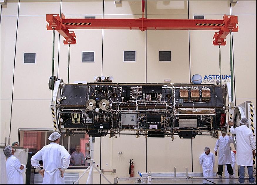
The satellite bus was manufactured by Airbus Defence and Space (Airbus DS) Geo-Intelligence/Infoterra GmbH of Friedrichshafen, Germany (formerly EADS Astrium GmbH) and delivered to Airbus DS, Spain (former EADS CASA Espacio) for further integration with the front-end of the PAZ-SAR instrument, including the SAR antenna.
PAZ SAR satellite mission of Spain
Spacecraft Launch Mission Status Sensor Complement Ground Segment Constellation References
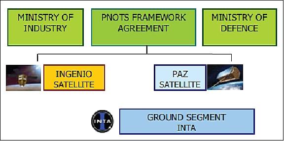
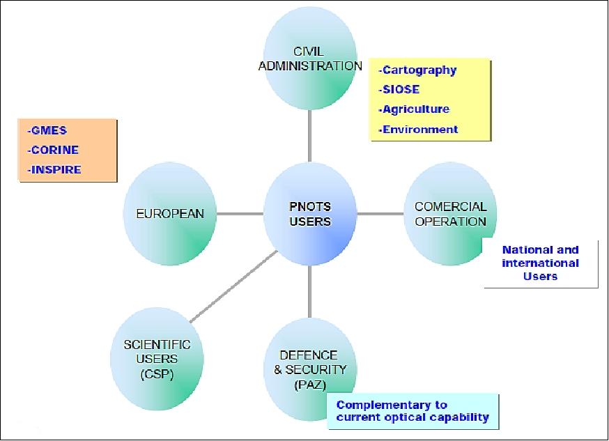
PAZ (“peace” in Spanish), formerly known as SEOSAR/PAZ (Satélite Español de Observación SAR - SAR Observation Spanish Satellite), is an X-band SAR (Synthetic Aperture Radar) mission of Spain, in fact a flagship mission of the Spanish Space Strategic Plan 2007-2011. The Spanish Earth Observation Program, referred to as PNOTS (Programa Nacional de Observación de la Tierra por Satélite), is based on two complementary satellites, namely:
• PAZ is an X-band SAR (Synthetic Aperture Radar) spacecraft based on the TerraSAR-X platform, to serve the security and the defense needs. The PAZ mission is a dual-use mission (civil/defense) funded and owned by the Ministry of Defense and managed by Hisdesat (Hisdesat Servicios Estratégicos, S.A., a Spanish private communications company providing also its services to the Ministry of Defense, since 2001.
• Ingenio , formerly also referred to as SEOSat/Ingenio, with the optical payload to serve the civilian users (space segment lead by CDTI/ESA). A launch is planned for 2015.
PNOTS is funded and owned by the government of Spain. INTA (Instituto National de Técnica Aeroespacial), the Space Agency of Spain, is managing the common ground segment of the two missions. Hisdesat together with INTA, will be responsible for the in-orbit operation and the commercial operation of both satellites. Airbus Defence and Space Spain (former EADS CASA Espacio) is the prime contractor leading the industrial consortia of both missions. 1) 2) 3)
A major goal of PNOTS is to maximize the common development, services, and to share the infrastructure between both missions (whenever possible). Both missions will also contribute to the GMES (Global Monitoring for Environment and Security) program of Europe. Hence, as third party missions of ESA, they must comply with the EO multi-mission environment scheme - and therefore to support HMA (Heterogeneous Mission Access) services.
The PAZ satellite owner is Hisdesat Servicios Estratégicos, S.A., Madrid, Spain, the PAZ ground segment owner is INTA. The dual use nature (civil/defense) of the PAZ mission imply security constraints within its ground segment. 4)
The institutional/industrial framework of the project is as follows: 5) 6)
- CDTI (Centro para el Desarrollo Tecnológico Industrial - Spain's Center for Development of Industrial Technology) is the PNOTS funding agent and is responsible for the programmatic aspects of the program.
- Astrium España (or EADS CASA España) is the prime contractor, responsible for developing and building the satellite within a period of 48 months.
- INTA (Instituto National de Técnica Aeroespacial - or Spanish National Institute for Aerospace Technology) is responsible for the ground segment, which includes two control stations: one in Torrejon near Madrid and the other in Maspalomas, located on the island of Gran Canaria.
- Hisdesat will be the satellite’s operator, responsible for all commercial exploitation. The Spanish Ministry of Defense will be one of Hisdesat’s main customers, and one of the main beneficiaries of the satellite’s capabilities.
Spacecraft
With a total mass of around 1350 kg, the satellite is 5 m in length and 2.4 m in diameter. The SM (Service Module), platform and instrument back-end, is based on that of TerraSAR-X and TanDEM-X. The satellite bus is manufactured by Airbus Defence and Space Geo-Intelligence/Infoterra GmbH of Friedrichshafen, Germany (formerly EADS Astrium GmbH) and delivered to Airbus DS, Spain (former EADS CASA Espacio) for further integration with the front-end of the PAZ-SAR instrument, including the SAR antenna. The AstroBus platform is designed as a hexagonal shaped body, with side panels at an angle of 60º. A deployable boom is needed to position the X-band downlink antenna, for data transmission. 8)
The S/C bus design features a central hexagonal CFRP structure as the main load carrying element. Three sides of the hexagon are populated with electronics equipment, while the sun-facing side is additionally carrying the solar array. The SAR antenna is mounted on one of the hexagon sides, which in flight attitude points 33.8º off nadir. The other nadir looking side is reserved for the accommodation of an S-band TT&C antenna, a SAR data downlink antenna - carried by a deployable boom of 3.3 m length in order to avoid RF interferences during simultaneous radar imaging and data transmission to ground - and a LRR (Laser Retro Reflector) to support precise orbit determination.
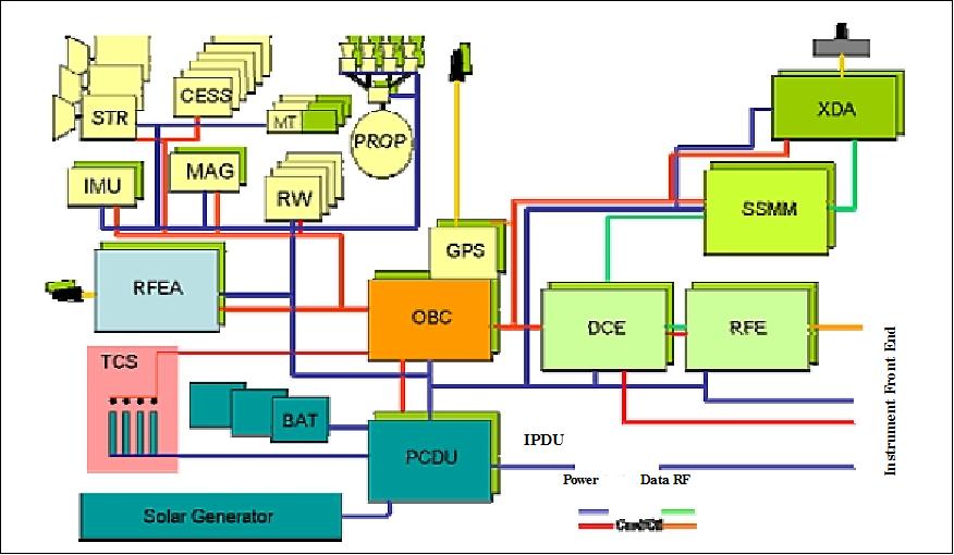
Onboard data handling: The newly developed ICDE (Integrated Control and Data System Electronics) system is being used as the central component for all avionics services. The ICDE core consists of two redundant 32 bit processor modules, implementing the ATMEL ERC32SC (Embedded Real‐time computing Core ‐ 32 bit Single Chip) processor, giving it a processing performance of more than 18 MIPS and enough memory capacity to handle full AOCS and data handling software tasks, leaving sufficient margins in performance and memory capacity for future extensions and redundancy concepts. A dedicated, hot-redundant reconfiguration module provides all necessary surveillance, reconfiguration, command and telemetry functions. The ICDE modules are cross-coupled, providing a fully redundant unit.
The ICDE provides the spacecraft and payload interfaces with the following standard link protocols: MIL-1553 bus, HDLC and SpaceWire. An optional GPS receiver module with optional star sensor processing fits seamlessly into the architecture; it is capable of acquiring and independently tracking of up to eight GPS satellites and provides position, velocity and time. The ICDE uses full duplex UART (Universal Asynchronous Receiver/Transmitter) interfaces to all ”intelligent” onboard equipment, except for the LCT experiment, where a MIL-STD-1553B bus is being used. The ICDE has a mass budget of 12-18 kg and a power demand of 15-30 W, depending on the configuration selected.
Mass of spacecraft | 1341 kg (wet mass), 1282 kg (dry mass) |
Spacecraft dimensions | Length: 5m, diameter = 2.4 m |
EPS (Electrical Power Subsystem) | - Body-fixed solar array of size: 5.25 m2, triple junction GaAs cells |
Thermal control | - Individually thermistor controlled heater circuits |
AOCS (Attitude and Orbit Control Subsystem) | - CESS (Coarse Earth & Sun Sensors) for acquisition and safe mode |
Data handling | - OBC processor type: ERC 32 |
RF communications | - Uplink (S-band encrypted), data rate= 4 kbit/s |
Spacecraft design life | 7 years (with a goal of 10 years) |
RF communications: A standard S-band TT&C system with 360º coverage in uplink and downlink is used for satellite command reception and telemetry transmission. The uplink path is encrypted. Generated payload (SAR) data are stored onboard in a SSMM (Solid State Mass Memory) unit of 256 Gbit EOL capacity prior to transmission via the XDA (X-band Downlink Assembly) at a data rate of 300 Mbit/s. The X-band downlink is encrypted. The on-board SAR raw data are compressed using the BAQ (Block Adaptive Quantization) algorithm, a standard SAR procedure. The compression factor is selectable between 8/6, 8/4, 8/3 or 8/2 (more efficient techniques can only be applied to processed SAR imagery). Both communication links are designed according to the ESA CCSDS Packet Telemetry Standard.
The X-band antenna is mounted on a deployable boom 3.3 m in length (the only deployable item on the S/C) to prevent interference with the X-band SAR instrument. This arrangement enables for simultaneous SAR observations and X-band downlink.
Development Status
• February 10, 2018: SPAIN is set to launch its first spy satellite, and Elon Musk's SpaceX company has agreed to blast it into orbit. PAZ is scheduled to be launched in February 2018. 10) 11)
- Built by Airbus DS, the satellite is owned by Madrid firm Hisdesat, although the Ministry of Defence and a number of private individuals provided most of the funding.
- The Spanish Armed Forces Intelligence Center, CIFAS, will receive 30 of the 100 high-resolution images captured daily by PAZ, with customers for the other 70 being sought.
- A contract with ESA ( European Space Agency) has already been signed, and the craft will also collaborate with the European Union's satellite center.
- Its main base will be the National Institute of Aerospace Technology in Torrejon de Ardoz, Madrid, with support from the Maspalomas station in Gran Canaria, while project leaders are exploring the possibility of a third station in the polar region.
- In addition to its military tasks, the satellite will also be used for mapping, environmental monitoring, urban planning and topographical studies.
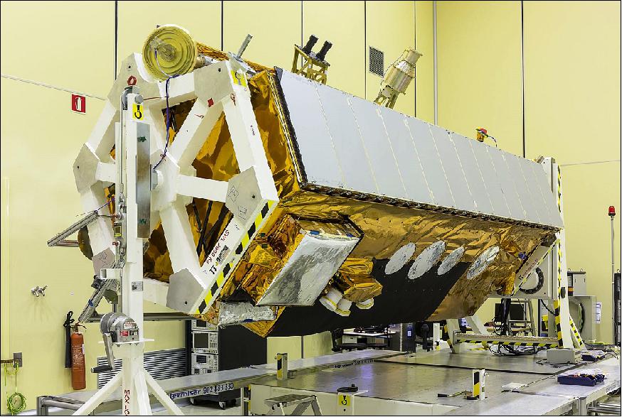
• November 22, 2017: The high resolution radar, Earth observation PAZ satellite will say its final goodbye to Spain, and will be shipped in December 2017 to its launch site in Vandenberg Air Force Base, California, USA. 12) 13)
- Airbus and Hisdesat, the Spanish operator of governmental satellites announce that the launch of the PAZ satellite will take place in the last week of January 2018. Since completion in 2015, Airbus has maintained the satellite in its Barajas cleanrooms, in Madrid, ready to be launched at short notice. José Guillamón, head of Airbus Space Systems in Spain stated that they had to be ready at all times as they could have got a green light at any moment. Close cooperation between Airbus as the prime contractor and Hisdesat as the owner and operator of the satellite has been a key factor in successfully reaching the final stages.
• March 2017: Airbus Defence and Space, as prime contractor, integrated the PAZ satellite at its facilities in Madrid, and was also responsible of the development of the radar instrument, leading a group of more than ten European companies (Ref. 22).
• In October 2014, the launch of the PAZ spacecraft is scheduled for Q1 2015 and the TerraSAR-X/PAZ constellation is planned to be operational in Q4 2015. This constellation program will be the blue print of a first of its kind coordinated constellation concept amongst X-band SAR satellites and is further scalable to add future satellite programs like TerraSAR-X-NG (Next Generation). 14)
• In the summer of 2014, the PAZ Ground Segment validation and verification phase is being conducted (Ref. 46).
• In September 2013, Astrium and Hisdesat are reporting a successful integration of the PAZ satellite. 15)
• In April 2013, the PAZ Ground Segment CDR (Critical Design Review) was completed.
Launch
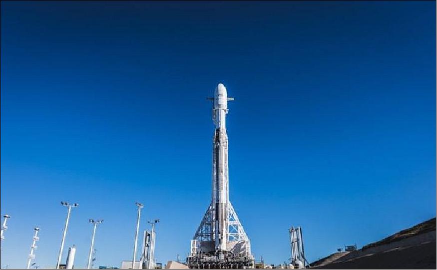
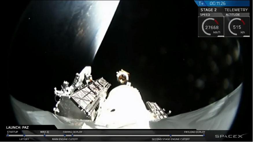
Launch: The PAZ spacecraft was launched on 22 February (14:17 UTC), 2018 on a SpaceX Falcon-9 v1.2 Full Thrust vehicle from SLC-4C at VAFB, CA. - Shortly after it reached orbit, the rocket deployed its payload (the PAZ Earth Observing satellite) as well as and two Starlink demonstrations satellites that will test SpaceX’s ability to provide broadband Internet service from orbit. 16) 17) 18)
First contact with the satellite was established from DLR/GSOC (German Space Operation Center), where Airbus engineers are supporting the LEOP (Launch and Early Orbit Phase) to check out and configure the satellite, ensuring that all satellite critical systems and communications are functioning as planned. After LEOP, the satellite will be handed over to the Ground Control Center located at INTA (Instituto Nacional de Técnicas Aeroespaciales) in Torrejón de Ardóz, near Madrid. The satellite will be operated by INTA and Hisdesat (owner of the satellite) technical teams.
The long wait for launch: Hisdesat had signed an agreement with SpaceX — after waiting for a launch approval from the Russian government to launch PAZ on a Dnepr vehicle of Kosmotras for more than 2 years. 19) 20)
The Spanish satellite operator Hisdesat is trying to retrieve money it paid Kosmotras for a long-overdue Dnepr launch of a radar satellite that Hisdesat has rebooked on a SpaceX Falcon 9 for a flight late this year. The satellite was originally supposed to launch on a Dnepr rocket in 2014 under an agreement Hisdesat signed with Kosmotras, a Ukrainian-Russian joint venture that has not launched a Dnepr since March 2015 because of difficulties winning Russian government approval for additional launches of the Ukrainian-built rocket. 21)
Hisdesat has since turned to the International Court of Arbitration in Paris to recover money it paid Kosmotras for the repeatedly postponed Dnepr launch. According to the Russian news service TASS, Hisdesat is seeking 15 million euros.
Orbit: Sun-synchronous dawn-dust orbit, altitude = 514 km, inclination = 97.44º, LTAN (Local Time of Ascending Node) at 18:00 hours. The nominal revisit period is 11 days (167 orbits within revisit period, 15 2/11 orbits per day).
Following the satellite's launch in February 2018, PAZ will be positioned in the same orbit as the German owned TerraSAR-X and TanDEM-X satellites and form a high-resolution SAR satellite constellation with them. The addition of this third satellite will reduce revisit time and increase acquisition capacity, leading to subsequent benefits to various applications. All three satellites will feature exactly identical ground swaths and acquisition modes. The new setup will be jointly exploited by Hisdesat and Airbus Defence and Space. 22)
Secondary Payloads
• MicroSat-2a, and MicroSat-2b. These are actually two minisatellites of SpaceX, each with a mass of 400 kg. They are identical prototype satellites to test technologies,dubbed Tintin A and Tintin B, for SpaceX's planned 4000-satellite Starlink constellation to provide broadband Internet access. The satellites will be deployed by the launch vehicle into an orbital plane of 514 km circular at 97.44 degrees inclination. After insertion, the satellite orbits will be raised to the desired mission altitude of 1125 km circular. — The plan of SpaceX calls for the deployment of more satellites in phases, reaching a total of 4,000 by 2024.
In this launch, Space-X did not attempt to land the first stage of the rocket on a sea-anchored barge. — Instead it tested the ability to catch one of the rocket nose cone's two falling fairings on a small ship mounted with a massive trampoline like those set up as safety nets under circus aerialists. The faring descended with a guided para-foil to slow its speed and carry it toward the ship. The catch failed, however, with the faring landing in the sea just a few hundred meters away from the vessel. - Catching the fairings, like retrieving the boosters, could generate significant savings for Space-X by allowing the company to recycle equipment.
Mission Status
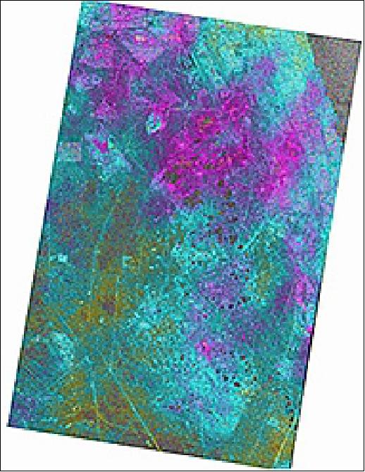
• February 28, 2019: Airbus Defence and Space and Hisdesat Servicios Estratégicos, S.A. have generated the first joint TerraSAR-X / PAZ Radar Interferogram. This milestone demonstrates the missions’ capacity for cross-sensor interferometry, whose processing is among the most challenging. 23)
- As PAZ is positioned in the same orbit as TerraSAR-X and TanDEM-X and features exactly identical ground swaths and acquisition modes, the three form a high-resolution SAR satellite constellation, jointly exploited by Hisdesat and Airbus. With the launch of PAZ, the observation repeat cycle has been divided by half, which improves the monitoring of fast ground deformation phenomena that can endanger lives and infrastructures.
- “This is a major step towards achieving the implementation of our TerraSAR-X / PAZ Radar Constellation. The level of accuracy obtained with this interferogram is a guarantee for our customers to continue to rely on the high quality standard we have set with TerraSAR-X and TanDEM-X, but with an improved monitoring capacity” said Hanjo Kahabka, Head of Production and Radar Constellation Manager at Airbus Defence and Space, Intelligence.
- “In Hisdesat we are very proud of reaching this milestone. Interferometry is one of the most technically demanding applications and thanks to this successful joint exercise with Airbus we have not only demonstrated the top performance of our PAZ satellite but its full compatibility with TerraSAR-X and TanDEM-X. Now operation in constellation can become a reality and we will be able to provide to our customers full set of images and services with the constellation.” said Miguel García Primo, Chief Operating Officer at Hisdesat.
• December 10, 2018: exactEarth Ltd. reports that its advanced AIS (Automatic Identification System) payload onboard the Spanish radar satellite, PAZ, has completed its commissioning phase and is now fully-operational. 24)
- Launched in February 2018, PAZ is in the dawn-dusk sun synchronous orbit that is occupied by a majority of the world's radar satellites. With an AIS payload onboard, for the first time AIS vessel signals and SAR (Synthetic Aperture Radar imagery can be combined to enhance global maritime monitoring capabilities.
- Supported by exactView RT, the Company's superior real-time satellite AIS service, the fusion of these two data sets can better assist maritime security and surveillance by rapidly correlating two data sources to identify so-called 'dark targets', which are vessels that should be transmitting AIS signals, but are not.
- "Our thanks and congratulations go out to Hisdesat on the successful launch and commissioning of the PAZ satellite," said Peter Mabson, CEO of exactEarth.
- "We now have 54 high performance satellite payloads in orbit capturing AIS data on more than 250,000 vessels daily and today's announcement helps to further solidify our leadership position in the industry and our differentiated technological capabilities. With the world's first AIS payload onboard a radar satellite, exactEarth is uniquely positioned to help its customers leverage the combination of AIS data and radar imagery to develop advanced maritime surveillance applications that enhance the security and safety of their interests."
• The PAZ satellite of Hisdesat entered its operational service phase on 6 September 2018, as announced by the Spanish Secretary of State for Defence, Mr. Ángel Olivares. 25)
Since the launch on 22 February, PAZ has successfully completed all planned phases for operational services:
- The LEOP phase ended on 9 March 2018
- The first image was received on 13 March
- The first orbital cycle was started on 3 April for the verification and adjustment of parameters, giving way on 16 April to the beginning of the planned phase of orbital cycles for calibration and validation of images.
- The last cycle was successfully completed on 5 September 2018.
- All verification steps of the spacecraft were carried out by a multidisciplinary team that included the participation of the Ministry of Defense (DGAM, CIFAS and CESAEROB), INTA, and the companies, Airbus and Hisdesat.
- With the start of PAZ satellite operations, the provision of services to the Ministry of Defense and other agencies of the Administration begins, continuing with the commercialization for the civilian use of radar images.
• As of July 2018, the PAZ mission is still in the commissioning phase, the project hopes to finish this phase soon. The PAZ project has an agreement with Airbus to work in constellation with PAZ, TerraSAR-X and TanDEM-X. The constellation will start as soon as the commissioning phase of PAZ is finished. 27)
• On 13 March 2018, the first PAZ image was successfully acquired, downlinked and processed, hence validating the tasking chain for the first time. 28)
- The LEOP is followed by 3-6 months of IOT (In-Orbit Testing) of the spacecraft, the radar instrument, and further secondary payloads such as the AIS (Automatic Identification of Ships) and the ROHPP (Radio Occultation and Heavy Precipitation with PAZ).
- The ‘PAZ Only’ commissioning phase of four months for spacecraft and ground segment will be followed by a TSX (TerraSAR-X)/PAZ Constellation commissioning phase of further three months during which several activities relevant for the constellation will take place: Enabling of the PAZ Ground Segment for the DRS (Direct Receiving Station) case, introduction of new modes Wide ScanSAR and Staring Spotlight and implementation of constellation harmonization measures.
- This Constellation commissioning will also verify the capability of the Constellation Service Segments on both sides such that either Airbus DS or HisdeSat can submit orders to any satellite TSX/TDX (TanDEM-X) or PAZ from their respective Ordering System.
• On 8 March 2018,PAZ reached its final orbit location after a two-week orbit drifting phase. The SAR instrument was subsequently activated and the first acquisitions (Madrid and Barcelona) were commanded (Ref. 28).
• Feb. 26, 2018: On behalf of Airbus Spain,DLR/GSOC (German Aerospace Center/German Space Operations Center) in Oberpfaffenhofen provided LEOP (Launch and Early Orbit Phase) support for the PAZ mission and a hand-over from DLR/GSOC ground control center to the nominal PAZ Ground Segment at the National Institute for Aerospace Technology (INTA) of Spain, located outside Madrid in the city of Torrejon. 29)
• Feb.22, 2018: The SpaceX company launched two experimental satellites today designed to help lay the foundation for Starlink, a network that, if all goes according to plan, will consist of thousands of spacecraft providing broadband Internet service to people around the world. 30)
- SpaceX representatives have said they hope to have Starlink operating, in at least a limited capacity, by 2020. Tintin A and Tintin B will gather data necessary to help meet the Starlink goal, but a lot remains to be done, company representatives stressed.
- Elon Musk revealed the broad outlines of Starlink in 2015, but SpaceX has been relatively quiet about the constellation since then. Last week, FCC (Federal Communications Commission) Chairman Ajit Pai announced that he had endorsed Starlink, but the plan has yet to garner official FCC approval.
Sensor Complement
PAZ-SAR (X-band SAR) Instrument
The PAZ-SAR instrument is designed and developed at Airbus Defence and Space, Spain [former EADS CASA Espacio (ECE)], Madrid (Barajas site), Spain. The instrument’s radar antenna will incorporate printed-radiator technology which has already been space qualified (for L-band, C-band, and X-band) implementations at ECE for photo-printed patch antennas (Ref. 2).
The objective of the PAZ-SAR instrument is to provide high quality SAR imagery in a variety of sizes and resolution ranging from medium over wide regions up to very high resolution (e.g. meter and sub-meter). Operational flexibility with multi-mode, multi-polarization and left and right looking attitude is one of the major PAZ System requirements leading to a quite large number of different instrument configurations and antenna beams. 31) 32)
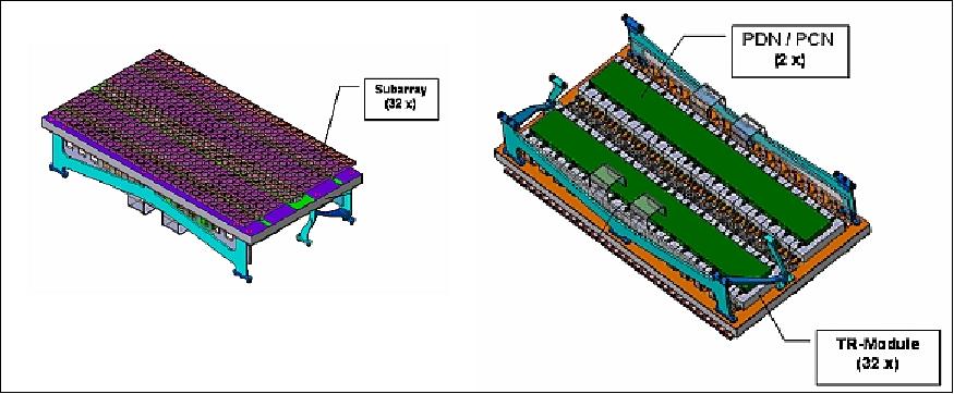
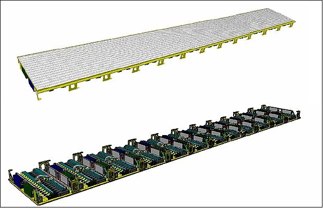
The PAZ-SAR instrument comprises an X-band active phased array antenna with an operation instantaneous bandwidth up to 300 MHz. The SAR antenna (with a size of 4.8 m x 0.7 m) consists of 12 panels in azimuth direction – assembled in three mechanical leaves – each with 32 dual-polarized subarrays. Each individual subarray is driven by a TRM (Transmit-Receive Module) adjustable in amplitude and phase by applying complex excitation coefficients. This enables beam steering and adaptive beam forming in both azimuth and elevation directions. For the variety of standard acquisition modes possible, such as Stripmap, ScanSAR or Spotlight, and some experimental modes more than ten thousand beams can be programmed and commanded. This multitude of beams is one highlight but also a great challenge for the whole mission and it represents the main driver for the need of an accurate antenna model. 33) 34) 35)
Compared to conventional slotted waveguide radiators, the instrument offers attractive features such as low profile, low-mass, flexibility of BFN (Beam Forming Network) topologies (possibility of using series or parallel feeding), easiness of manufacturing (capability of maintain a series production) while providing good radiation efficiency and low losses. The beam forming network is full corporate and it is implemented in low-losses stripline technology. Tests on first subarray breadboards are presented, showing ohmic losses around 0.5 dB, good polarization purity (cross-polar better than -25 dB) and good bandwidth performances regarding radiation patterns and sidelobes.
Each panel consists of 32 dual-polarized stripline technology subarrays, arranged in elevation, each with a dedicated TRM (Transmit/Receive Module). Each panel has a PDN (Panel Distribution Network) for splitting/combining radar (Tx/Rx) signals, a PCN (Panel Calibration Network) for splitting/combining calibration signals, two PSUs (Panel Supply Units) to power the TRMs, and one PCU (Panel Control Unit) to control the TRMs. 36)
A subarray is a 16-element array of size 400 mm x 22 m. The antenna thickness is 9 mm (excluding connectors) and the estimated mass is 80 gram.
Array radiator: The array radiator is a circular patch excited by electromagnetic coupling through two orthogonal stripline probes, coupled to a ring aperture and providing both horizontal and vertical polarizations. Both stripline probes and radiators are photo-printed in a low-loss Teflon-based substrate. The aperture coupled patch radiators offer good electrical performances in terms of input matching (better than -18 dB in the full 300 MHz bandwidth) isolation between ports (better than -22 dB), low efficiency losses and high directivity (since the substrate has a very low dielectric constant), and good polarization purity (cross-polar better than -20 dB that is further improved at the array level).
BFN (Beam Forming Network): The BFN provides uniform amplitude and phase to the elements in the array. It is a fully corporate network to cover the entire bandwidth (3% at 9.65 GHz) and so it prevents the decrease of directivity, null filling and increase of the sidelobes level that occur in a series feeding at the band edges. Parallel feeding is more insensitive to any kind of variation such as thermal effects, tolerances and manufacturing errors.
Due to available space, BFN is divided into three levels as shown in Figure 13.
• Probes layer: It includes horizontal and vertical probes for each radiator and the first two-way divider stage for the array. In the case of the vertical polarization, it is a two-way equal-phase reactive divider while for the horizontal polarization to two-way divider includes a 180º transmission line to implement the sequential rotation.
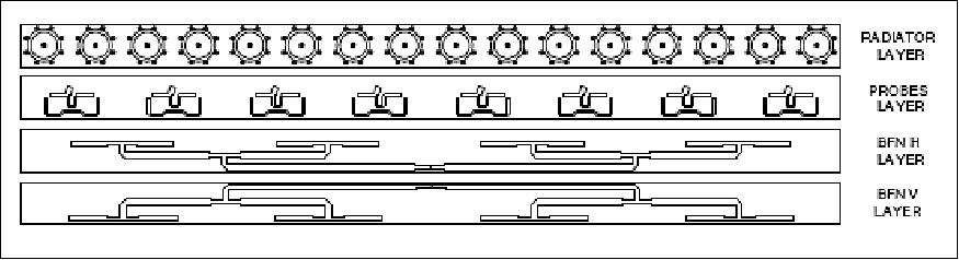
• BFN 1 to 8 is being used for horizontal polarization. It is a reactive divider based on λ/4 transformers feeding the eight pairs of radiators.
• BFN 1 to 8 is also being used for vertical polarization. It features the same design as in the horizontal polarization.
The probes layer is joined to the BFN 1 to 8 through vertical transitions based in small coaxial sections and properly tuned to the working frequency. The subarray output uses a male SMA (SubMiniature type A) connector.
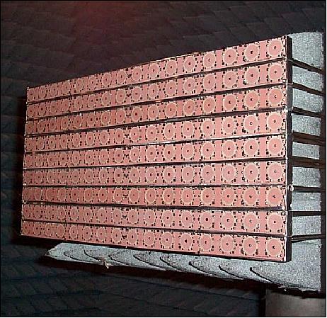
First subarray breadboards show adequacy of the X-band design featuring low losses and low efficiency losses, while adhering to the attractive performances of this technology in terms of low profile and low-mass design.
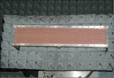
Subarray test results (embedded performances): The subarrays have also been tested in an embedded configuration in order to characterize the radiation pattern performances in their actual panel configuration. The measured subarray is surrounded by other 8 subarrays in order to simulate the most relevant couplings in the panel (composed by 32 subarrays).
The X-SAR system design offers the following support modes of operation:
- Spotlight: Imagery of size 10 km x 5 km @ 1m resolution, or 10 km x 10 km at 2 m resolution
- ScanSAR: Imagery on a 100 km swath @ 15 m resolution
- Stripmap: Imagery on a 30 km swath @ 3 m resolution (single polarization), or 15 km swath @ 6 m (dual polarization).
The mission goal is to provide more than 200 SAR images per day.
Parameter | Value | Parameter | Value |
Antenna type | Active phased array | Beam scan angle range | ±0.75º (az), ±19.2º (el.) |
X-band center frequency | 9.65 GHz (3.1 cm wavelength) | Incidence angle access range | 15º - 60º |
Antenna aperture size | 4.8 m x 0.8 m x 0.15 m | Radiated peak power | 2260 W |
Phase centers | 12 (az.) x 32 (el.) | Stripmap duty cycle | 18% (on transmit) |
Polarization modes | HH/VV/HV/VH | Spotlight duty cycle | 20% (on transmit) |
System noise figure | 5.0 dB | Operational PRF range | 3000 - 6500 Hz |
Selectable BAQ compression rates | 8 to 4, 3, 2, by-pass | ADC sampling rates (8 bit, I&Q) | 110, 165, 330 MHz |
Max receive duty cycles | 100%, 67%, 33% | Chirp bandwidth range | 5 - 300 MHz |
SSMM (Solid State Mass Memory) capacity | 320 Gbit (BOL), | PAZ-SAR instrument mass | 394 kg |
Quantization of signal | 8 bit I, 8 bit Q | SAR data compression | online BAQ |
Nominal look direction | Right side of groundtrack | Yaw steering | Yes |
Imaging mode | Polarization mode | Label | Scene size (azimuth, range) | Resolution (azimuth, range) | NESZ | DTAR |
Stripmap | single polarization | SM-S | 30-2000 km, 30 km | 3 m x 3 m |
< -21 dB |
|
ScanSAR | single polarization | SC | 100-2000 km, 100 km | 16 m x 6 m | ||
Spotlight | single polarization | SL-S | 10 km x 10 km | 1 m x 1 m | ||
HR Spotlight | single polarization | HS-S | 5 km x 5 km | < (1 m x 1 m) |
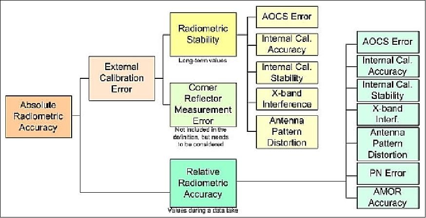
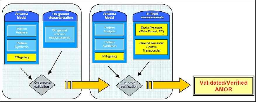
PAZ-SAR instrument calibration
The requirements call for a minimum end-to-end calibration time to impact on the operation time of the instrument (to cope with system degradation, SAR performance, or with need for long re-calibration periods). After the lessons learnt during the TerraSAR-X (TSX) commissioning, an effective calibration philosophy emerges which basically shifts the calibration effort from space to the ground in order to assure a commissioning phase of less than six months (Ref. 31).
The PAZ-SAR instrument architecture is similar to the TSX-SAR instrument of TerraSAR-X; hence, a similar instrument calibration strategy has been established, including internal and external calibration methods, as well as phase-coded individual TRM measurements. However, even though this is a consolidated strategy, the new front-end design and the high degree of flexibility in the instrument calibration and operation requires a careful evaluation of the error sources, correction methods and the impacts in the overall instrument radiometric budget (Ref. 8). 37) 38)
The PAZ-SAR operation and calibration approach is built around an antenna model called AMOR (Antenna MOdelleR). This tool is used to accurately determine the antenna beam patterns combining mathematical models with highly precise on-ground characterization data, post-launch external verification measurements and periodic in-flight TRM calibration (Ref. 31).
AMOR is developed by the UPC (Universitat Politècnica de Catalunya), Barcelona, under EADS Casa Espacio contract. AMOR permits the reconstruction of the antenna radiation patterns by superposition of measured embedded subarray patterns weighted by beam excitation coefficients, considering the antenna geometry and elements referencing. Another important function to be implemented into the SW tool is the beam excitation coefficients optimization, in order to maximize the performance w.r.t the NESZ (Noise Equivalent Sigma Zero) and ambiguity ratio parameters; an eventually re-computation may be required in response to TRMs failure or degradation. In addition, the tool includes the analysis of the effects due to eventual antenna subarray misalignment and planetary errors, favoring a better fit to the desired patterns. The frequency dependence as well as thermo-elastic deformations can be assessed.
The key element of this new calibration concept is a mathematical antenna model (AMOR) based upon accurate on-ground measurements of the instrument, a set of post-launch external measurements to be performed during the initial commissioning period, periodic in-flight internal characterization, and the internal calibration data to be performed during and together with the sensing data. This tool plays an important role in the performance prediction of the entire instrument and allows for dynamic re-calibration during operational lifetime, so its required accuracy has to be carefully managed and verified.
AIS (Automatic Identification System)
The AIS payload on board PAZ is part of the exactEarth constellation (exactEarth Ltd. is based in Cambridge, Ontario, Canada). The overall objective is to provide a SAR data fusion capability for maritime surveillance from space with AIS data services. Hisdesat is a 27% shareholder of exactEarth in Canada in joint venture with COM DEV. 39)
• Commanding is done through the PAZ main ground station at Torrejón (Madrid). Nominal downloading of AIS information is in Svalbard (located near Longyearbyen on the island of Spitsbergen, Norway). Other possibilities are in Guildford and Cork (UK).
• AIS antenna footprint has narrower size due to lower satellite orbit altitude.
• Dual polarization receiver. The entire signal spectrum is downloaded for de-collision of the AIS messages.
There are complementaries between AIS and SAR data:
• Although it was born as an anti-collision system, S-AIS (Satellite AIS, also written as “SAIS”) complements other systems such as VMS (Vessel Monitoring System) and LRIT (Long Range Identification and Tracking) as a generic source of vessel positioning data.
• Still, in order to achieve the most accurate maritime situational picture, an independent observation is required in order to verify the vessels that are present in the area. The SAR can provide such source of data due to its all-weather, day/night capability.
• The use of SAR images for maritime reconnaissance requires of the balancing between image coverage and resolution in order to set the optimum degree between detection rate and level of information to be extracted from the image.
• Intelligence applications normally require very high resolution data while environmental applications (e.g. fisheries, pollution, etc) concentrate in larger areas.
• However, unlike optical images, SAR detected vessels are more difficult to identify.
There are some challenges in fusing AIS and SAR data.
• In order to use VDS (Vessel Detection System ) given at an instant and S-AIS information, interpolation and matching of the data has to be performed.
• The problem is that AIS/S-AIS data is not always available at the moment of the acquisition therefore interpolation is required.
• The interpolation of data has several problems:
- Navigational routes do not always follow straight lines (e.g. Central Atlantic) in all areas of the globe (e.g. Red Sea).
- Navigational information is not always accurate (e.g. speed over ground, etc) therefore the most accurate speed parameters have to be estimated from the vessel positions rather than from the AIS messages.
- Time interval between image acquisition time and AIS targets becomes critical and information easily de-correlates beyond ΔT = 5-10 minutes (depending on the area) and type of ship (e.g. a cargo ship normally moves in straight line therefore is more predictive while a fishing vessel is more erratic).
• Vessel speed can not be measured from the image unless the wake is visible. Therefore AIS speed and heading has to be taken into account to correct positions prior to SAR-SAIS target matching. Recently, other methodologies to estimate the speed from the image itself based on sub-looks images analysis have been developed but results are not yet fully verified. The problem is that with current systems, SAIS data is interpolated therefore it is not sure that this effect can be accurately corrected.
• Size properties are difficult to measure as it has been seen from defocusing. However an estimation has to be measured in order to use the size as a input value for the cost function in the VDS-SAIS correlator.
• Dense traffic areas are a problem for SAIS due to IS message collisions coming from different SODTMA (Self Organizing Time Division Multiple Access) cells. Therefore the quality of the SAIS is a key to avoid mismatching of erroneous SAIS and VDS contacts; de-collision methodology improves the detection of messages and seems more convenient in order to avoid errors and improve id of VDS targets.
Summary:
• For the first time a satellite will integrate a SAR and an AIS receiver onboard.
• PAZ SAIS data will be integrated into exactEarth and the processing chain is independent from PAZ processing. SAIS delivery is done via web services data access.
• The synergistic use of both payloads shall overcome the current limitations of SAR-SAIS correlation. In particular, the time synchronization between both data sources which is critical for the successful matching of VDS-SAIS contacts.
• The information contained in SAIS messages (speed and heading) will need to be accounted (correct position of the targets) for in order to achieve a correct matching between SAIS and VDS targets therefore quality SAIS data is required. To this aim, processing seems a ‘must’ specially in areas of high density traffic. ExactEarth is the only company that possesses such technology.
• The availability of a polar station or a DAS (Direct Access Station) can enhance the systems to a Near Real Time (NRT-30 minutes) delivery capability on areas of interest (e.g. Europe).
• For some users (DAS) in addition to baseline SAR processing capability, VDS and SAIS correlator processor can be incorporated to the facility to reduce latency periods (time between image acquisition and VDS-SAIS fused product delivery to end users).
• The analysis of SAIS anomalies seems promising to direct the datatakes of SAR sensors, in particular for PAZ where tracking of vessels shall be more straight forward due to the SAIS payload onboard.
ROHPP (Radio Occultations and Heavy Precipitation with PAZ)
The global atmospheric community (weather and climate) is seeking EO missions which can support RO (Radio Occultation) observations to continue the global service which has been provided over the past years. However, the missions that are currently flying RO instruments, are close to the end of their mission life or already beyond their mission life. In order to avoid an observation gap in the near future, the PAZ project was approached by the international community to include RO observations in their mission.
In 2009, the Spanish Ministry for Science and Innovation (MICINN) approved the RO proposals, aimed to include a polarimetric Global Navigation Satellite System (GNSS) Radio-Occultation (RO) payload on board of the Spanish Earth Observation satellite PAZ. The PAZ mission was initially designed to carry a Synthetic Radar Aperture (SAR) as primary and sole payload, and included an IGOR+ advanced GPS (Global Positioning System) receiver and corresponding antennas for precise orbit determination. The design and software of this GPS receiver allows the tracking of occulting signals, that is: signals transmitted by GPS satellites setting below the horizon of the Earth (or rising above it). 40)
RO profiles are assimilated operationally into several global NWPMs (Numerical Weather Prediction Models). The latest results at NCEP (National Centers for Environmental Prediction) show that ROs improve anomaly correlation scores by ~8 hr starting at day 4 and increases with extended forecast range. It also helps reducing model biases. ECMWF (European Centre for Medium-Range Weather Forecasts) compared the impact of 24 operational observation systems, GPS-RO impact resulting among the top-five. The use of GPS RO has been shown to significantly improve models forecast skill, and is a key component of the operational observing system.
Missions currently providing currently RO profile information are: 41) 42)
• FormoSat-3 / COSMIC (Taiwan/USA constellation of 6 spacecraft) with a launch on April 15, 2006. Instrument: IGOR (Integrated GPS Occultation Receiver).
• MetOp mission of EUMETSAT with a launch on Oct. 19, 2006. Instrument: GRAS (GNSS Receiver for Atmospheric Sounding).
• GRACE (US-German mission) with a launch of March 17, 2002. Instrument: BlackJack (GPS Flight Receiver).
The above missions provide about 2500 daily RO profiles evenly distributed all over the Globe. They are most useful for climate studies (long time series of RO data required) and for weather predictions (short time series of RO data required). In particular, a post FormoSat-3 / COSMIC observation gap may occur until the follow-up constellation (12 spacecraft) of FormoSat-7 / COSMIC-2 is operational (2 launches are planned for 2015 and 2017).
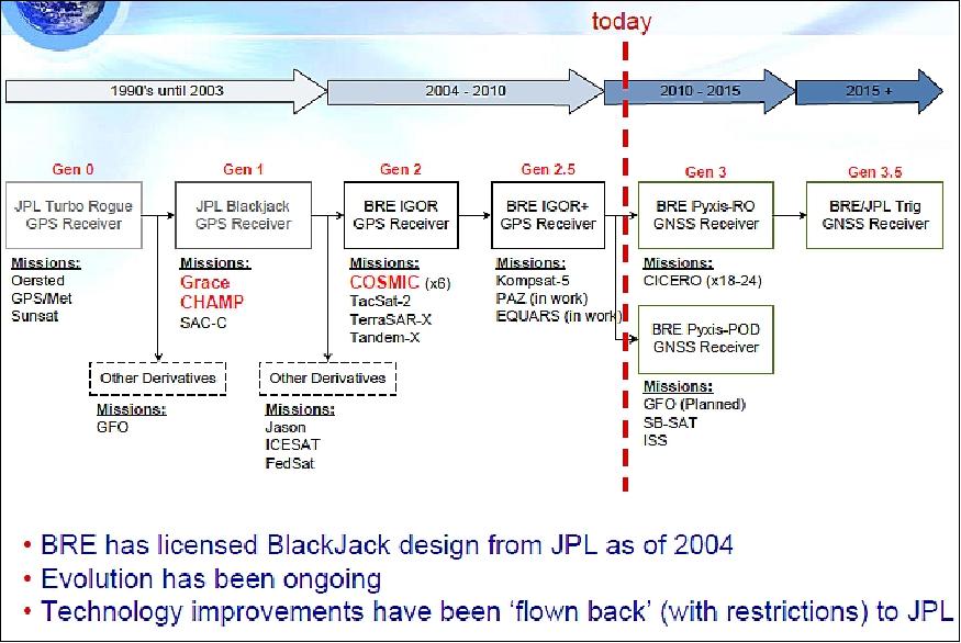
The ROHPP instrument makes use of the original IGOR+ receiver on PAZ. Minor modifications on IGOR+, together with deploying the dedicated antennas, are the basic steps required to achieve the desired capabilities. Moreover, polarimetric RO will be added, becoming a proof-of-concept experiment for the detection of heavy precipitation. This will be the first time that polarimetric GPS signals are captured from space, and the first attempt to monitor precipitation by means of RO techniques.
The PI of the ROHPP instrument is Estel Cardellach of ICE (Institut de Ciencies de L'Espai), Barcelona, Spain. The funding institution is MICINN. The ROHPP collaborative institutions are: NOAA and UCAR in the ground segment.
ROHPP experiment (Ref. 41):
• 1 single RO antenna (setting observations) with two linear polarizations
• The two linear polarization can be recombined in post-processing to get both Right-Hand and Left- Hand Circular Polarization components (RHCP and LHCP, respectively)
• RHCP: standard RO measurements
• LHCP: This represents the polarimetric experiment aiming to capture [heavy] precipitation.
• Heavy precipitation increases drops size, resulting in a flattened shape
• Signal crossing drops along the flattening axis suffers depolarization
• RO cross lowermost atmosphere tangentially (aligned with the most common flattening axis)
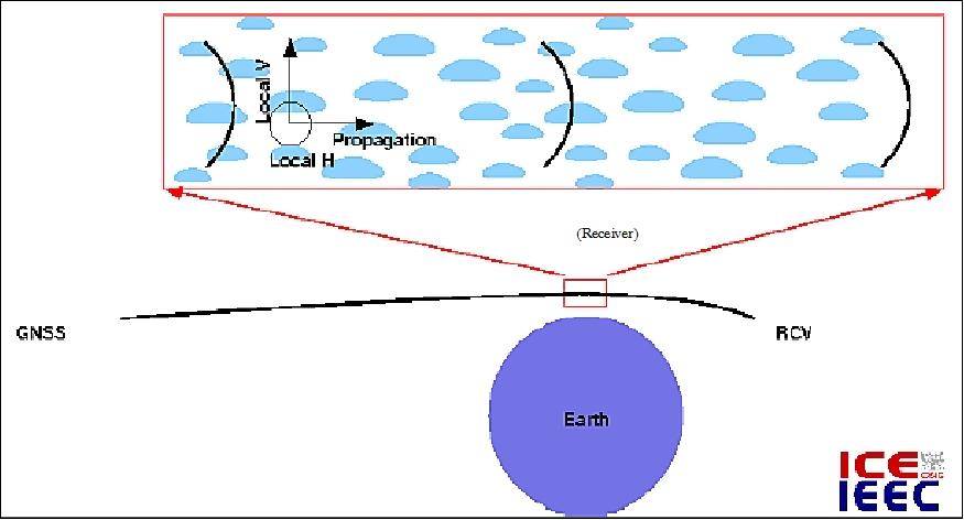
Legend to Figure 21: In the low troposphere, the RHCP GPS signal propagates tangentially, aligned with the plane of flatness of the rain drops, situation in which the de-polarization effect is maximal. The receiver on board the PAZ mission will collect both RHCP (Right-Hand Circular Polarization) and LHCP (Left-Hand Circular Polarization) components.
ROHPP equipment:
• The IGOR+ receiver is modified (as in other RO missions). The modifications are made by BRE (Broad Reach Engineering); IGOR is a product of Broad Reach Engineering.
• Antenna:
- Azimuth range: ± 55-65º
- Elevation range: ± 3-7º
- Dual Polarization: V/H (Vertical/Horizontal)
- Dual Frequency: GPS L1/L2
- Gain 10-12 dB each port (V/H) ⇒ 13-15 dB circular.
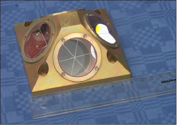
LRR (Laser Retro Reflector)
The PAZ spacecraft features LRR for an independent orbit determination of LEO (Low Earth Orbiting) satellites. LRR is developed at GFZ Potsdam and is of CHAMP, GRACE, TerraSAR-X,TanDEM-X , KOMPSAT-5, and Swarm constellation heritage.LRR has four corner cube prisms mounted in a compact frame. 44)
Verex length | 28 mm |
Clear aperture of the front face | 38 mm |
Dihedral angle offset | -3.8" (smaller than 90º) |
Radius of curvature of the front face | +500 m (convex) |
Index of refraction @ 532nm | 1.461 (fused quartz) |
Nominal separation of the far field maxima | 24" |
Nominal width of the far field peaks (20% intensity of max.) | 10'' |
Ground Segment
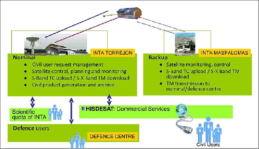
A ground segment (within the framework of PNOTS) for both missions, PAZ and Ingenio) is allocated to INTA (Instituto National de Técnica Aeroespacial) in Torrejón de Ardoz near Madrid (primary or nominal system) and in Maspalomas, located on the Canary Islands (backup system). INTA and Hisdesat will be the operators of the system and are involved in the ground segment development (Ref. 1). 45) 46)
PAZ is a dual use (civil/defense) mission - providing also its data to the GMES (Global Monitoring for Environment and Security) program of the EU. The defense implementation requires security constraints.
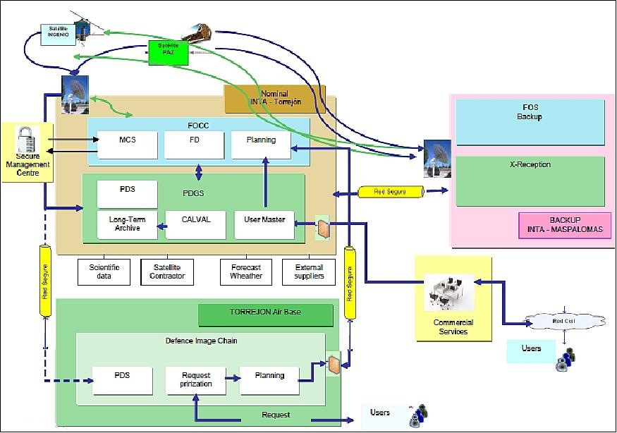
The PGS (PAZ Ground Segment) is a multi-mission ground segment featuring a HMA (Heterogeneous Mission Access) implementation as used in the GMES initiative.
The PGS is providing the following functions: 47)
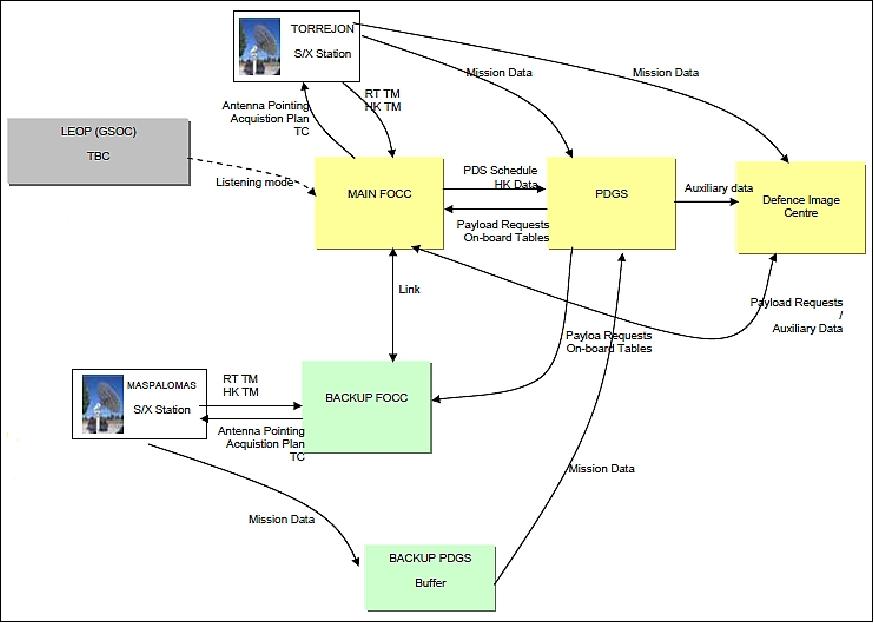
• FOS (Flight Operations Segment): The main functions of FOS are the operation and control of the satellite and the provision of telemetry. It is divided in a FOCC (Flight Operations Control Center) and the following subsystems:
- G/S (Ground Station) operations, which includes the S- and X-band functions for signal modulation/demodulation.
- ARF (Acquisition & Routing Facility), in charge of the second level of synchronization, generation of ISP files and routing to the Nominal PDGS or the Defence one.
- SMC (Secure Management Center. CFI) in charge of TC authentication/ciphering and key management.
- FMC (FOS Monitoring and Control), in charge of segment monitoring and G/S interfacing.
The main functionality of the FOS is included in the FOCC , which performs, between others, the tasks of planning and satellite commanding. The main subsystems involved here are:
- MPF (Mission Planning Facility), in charge of planning the satellite activities for the following days, including platform and instrument ones.
- IO (Instrument Operations), in charge of generating the commands needed to perform a data take acquisition. This subsystems works on a day-to-day basis leaving the task of planning the other instrument activities needed to allow the correct data acquisition to the MPF.
- FD (Flight Dynamics), in charge of orbit control and the generation of the required orbit and attitude products.
- MCS (Mission Control System), in charge of convert the schedule generated by MPF to TC and the uplink to the satellite. Also it receives the S-band TM and generates the HK reports.
- SSIM (Spacecraft SIMulator, CFI), to simulate the satellite. This simulator doesn’t support instrument TCs.
• PDGS (Payload Data Ground Segment): The PDGS is in charge of managing the user requests, data archiving, processing and calibration/validation. To perform these tasks, PDGS consists of the following systems:
- MUS (Master User Services). This subsystem is the only that interacts with the user, receiving the user requests and providing to it the obtained products. It also generates the internal orders required to start the PGS flow.
- PDS (Payload Data System). This subsystem is the core of the PDGS and it is in charge of deciphering and processing the raw data in order to obtain the desired products and also circulating all data flow inside the segment.
- CALVAL Center (Calibration and Validation). The tasks performed in this subsystem are the maintenance of the SAR system configuration (satellite and PGS), the calibration, characterization and validation of SAR products and the management of the scientific exploitation.
- MAC (Mission Archive & Catalog), in charge of the storage and catalog of processed data and all the necessary information required in the PDGS.
- PM (Performance Monitoring), in charge of the monitoring of all system performance.
• PGS Operational Concept: PGS operations are performed in a data driven model, conducted by user request reception. User requests are introduced in PGS via the MUS (Master User Services) subsystem. Three different types of request are supported by PGS:
- Dissemination Request; with this operation the users are able to get L1B products currently present in PAZ archive.
- Processing Request; in this case the users consult the PAZ catalog to know past acquisitions that match their interests (specific area of interest, acquisition time period, imaging mode, etc), performing a request of the product in a Level1b different to the stored in the PAZ archive.
- Acquisition Request; intended to obtain a future raw data acquisition. Users can select acquisition and processing parameters such as: area of interest, time acquisition window, imaging mode, beam, polarization and L1B processing level.
All the requests have to pass an approval stage to be ingested in the PGS chain. After this operation the working flow for the requests depends on their type. Dissemination requests are directly sent from MUS to the MAC. MAC extracts from PAZ archive the desired product that is transferred to MUS to be delivered to the user.
Processing requests are managed by PDS, that extracts from MAC the L0 product to be processed up to desired L1B level and it solves the dependencies related to the auxiliary data needed to perform the processing. Once all the dependencies are solved, PSP performs the processing and the resulting product is temporally archived into the MAC and delivered to the user via MUS.
Acquisition requests are managed in a first stage by MUS. Once the user has inserted in the subsystem his request, MUS performs a feasibility analysis giving to the operator a list of potential acquisitions matching his search criteria. The user will select from the list the acquisition or set of acquisitions to be performed, generating the final User Request. Feasibility analysis takes into account satellite maneuvers that prevent acquisitions as well as possible conflict problems due to another user request. Nevertheless, although the possible conflicts between requests are showed to the user, the acquisition can be requested anyway.
Taking into account all the final acquisition requests introduced in the system, MUS generates in a daily basis the DTOL (Data Take Order List), which contains all the possible data takes that can be acquired in the next programming horizon of the mission (at present set to 72 hours).
Civilian and Defence DTOL are sent to the MPF, which is in charge of generating the final plan. This plan is performed taking into account all the acquisitions requests as well as the satellite maneuvers, ground station unavailability and visibilities and satellite constrains. MPF has to solve the conflicts that can arise between users requests coming from nominal and defence centers, performing an algorithm which uses the different user roles and priorities.
• PAZ Basic Products Portfolio: The PAZ system can operate in four imaging modes:
1) Stripmap, with single or dual polarization. Azimuth resolution 3.3 m (single pol.), 6.6 m (dual pol.); L1B ground range x product length 30 x 50 km (single pol.); 15 x 50 km (dual pol.).
2) ScanSAR, with single polarization. Azimuth resolution 18.5 m ; L1B ground range x product length 100 x 150 km.
3) Spotlight, with single or dual polarization. Azimuth resolution 1.7 m (single pol.) | 3.4 m. (dual pol.); L1B ground range x product length 10 x 10 km.
4) High Resolution Spotlight, with single or dual polarization. Azimuth resolution 1.1 m (single pol.); 2.2 m. (dual pol.); L1B ground range x product length 10 x 5 km.
The operational image products will have a level L1B of processing, with four variants:
- SSC (Single Look Slant Range Complex); available for Stripmap, ScanSAR and High Resolution Spotlight.
- MGD (Multi Look Ground Range Detected); available for all imaging modes.
- GEC (Geocoded Ellipsoid Corrected); available for all imaging modes.
- EEC (Enhanced Ellipsoid Corrected); available for all imaging modes.
The PAZ SAR Processor is a DLR development integrated in the Ground Segment. The format of L1B products keeps the structure of TSX/TDX ones, allowing compatibility between applications made for products of these missions.
A backup capability is provided in Maspalomas (Canary Islands) with an S/X-band station, FOCC, and a temporal archive.
The PGS advances in coordination with the IGS (Ingenio Ground Segment), also supporting the HMA (Heterogeneous Mission Access) interface. HMA is a technique which is being implemented for the ground segment of the GMES program in Europe to accomplish coherent access to archives to support scientific exploitation like the Climate Change Initiative. HMA is being implemented by ESA, DLR, CNES, EUMETSAT, MDA (RADARSAT), INTA, etc.
In November 2011, INTA awarded a contract to the Spanish information technology company Indra to provide the ground control segment for Spain’s PAZ radar Earth observation satellite. 49) 50) 51)
TerraSAR-X and PAZ Constellation
In April 2012, Astrium GEO-Information's German unit, Infoterra GmbH, and Hisdesat, the Spanish government satellite service operator, have signed a framework agreement for a joint technology development project that aims to establish a constellation approach with the TerraSAR-X/TanDEM-X and PAZ radar satellites.
The agreement between Airbus DS and Hisdesat defines the joint development and coordination of their space, ground and service segments. The two satellite operators will establish interfaces enabling them to have a system overview of both satellites’ tasking plans and establish simplified data ordering and delivery procedures. The owner companies of the respective systems will retain complete control of their satellites, while being able to better coordinate acquisition planning and satellite tasking. It is the first international collaboration to bring together two national X-band radar remote sensing satellites in an effort to improve revisit and acquisition capabilities, enhance service levels and application opportunities for both public and commercial customers. 52) 53) 54) 55) 56) 57) 58)
The cooperation will include the development of an aligned tasking approach for the two missions, harmonized ground segment operation, an integrated processor for both satellites as well as complementary order and delivery interfaces. The agreement also envisions joint marketing of products and services generated by the constellation approach.
Operating the two virtually identical satellites will afford Astrium and Hisdesat more efficient and flexible management of system capacity. Both companies will be able to offer their customers and partners enhanced performance and services levels. The key advantages of the TerraSAR-X / TanDEM-X / PAZ constellation will be:
• Shorter revisit times
• Increased data acquisition capacities
• Improved service reliability.
A wide range of time-critical and data-intensive applications will benefit from the constellation, including defense and security, surface movement monitoring, maritime surveillance, disaster management. Shorter revisit times and increased capacity will provide improved levels of responsiveness and acquisition opportunities worldwide. The constellation will offer improved InSAR capabilities for precise monitoring and detection of faster surface-movement activities. The constellation approach will also provide improved system redundancy and back-up for both satellites during maintenance phases. 59)
Constellation Phasing
Figure 29 highlights the various options for positioning the PAZ satellite in the TerraSAR-X orbital plane. The satellites will fly in the same orbit tube (i.e. with a diameter of 500 m) and shall keep the same ground track, in order to limit the interferometric baseline and ensures a regular update of data stacks (Ref. 14).
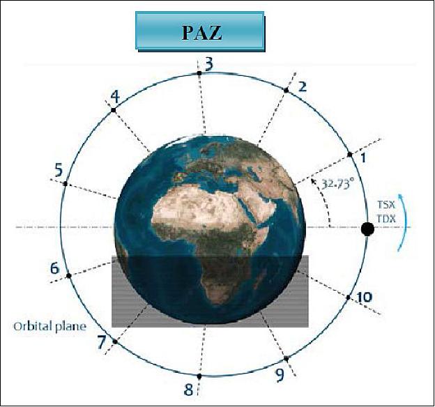
As shown in Figure 29, the TerraSAR-X / TanDEM-X satellites are assumed to be located at position 0 in the orbital plane. According to the 11 day TerraSAR-X repeat cycle and with the objectives of achieving an interferometric revisit with the PAZ satellite there is an option of selecting 10 slots that allow having the same ground tracks with the same orbital plane. Five out of the ten orbital slots, separated by 32.73º, are symmetric (offering same interferometric revisit) in nature, so for practical purposes the possible candidate for the PAZ satellite are shortlisted from position 1 to position 5.
In the available 5 positions, the PAZ satellite has been decided to be placed in position 3 due to the following reasons:
• Optimized interferometric revisit 4 and 7 days thus reducing the current TerraSAR-X interferometric revisit into half.
• Position 3 means an approximate 30 minute orbit separation between TerraSAR-X and PAZ; this arrangement makes it possible for direct access customers (even having single receiving antennas) to access both the satellites in one orbit pass.
• Daily global revisit is achieved by the constellation (left and right looking mode) for mapping and monitoring applications (Figure 30).
• Also, the positioning of PAZ in front of the TerraSAR-X / TanDEM-X formation flight gives Airbus DS and DLR the flexibility to experiment different separations for the pursued formation flight.
Constellation CONOPS (Concept of Operations):
For commercial constellation operations, a detailed CONOPS has been agreed by Airbus DS and Hisdesat. In this section we highlight the key features of the planned CONOPS:
• The TerraSAR-X and PAZ satellites, although commanded from their respective ground segments in Torrejón and Neustrelitz, would share the same commercial order submission deadline (2 times a day).
• A harmonized ordering and priority access scheme for both the missions has been devised and agreed to for the constellation.
• Both the missions will have the same customer service procedures, policies and working times. The customer service teams in both companies will work very closely together, with a joint acquisition plan encompassing both the missions to meet the customer demands in the fastest possible manner.
• Both TerraSAR-X and PAZ imagery products will have harmonized product structure and delivery formats and quality standards.
• Both companies have also agreed to market the products at the same commercial price list and present one face to the customer through both the commercial ordering systems.
• Depending upon special customer and application needs, the customers would have the option to choose one mission over the other.
• Customers requiring near real time access will have the option of owning a joint direct access capability or can also choose to use one of the polar stations like Svalbard for quick data access from both missions.
• A copy of the TerraSAR-X and PAZ mission data accessed by customers via the multimission direct access capability would be repatriated to the respective ground segments (due to mission data ownership regulations).
• Harmonized ordering and data secrecy provisions for sensitive customers accessing the missions.
As the market for spaceborne products and services grows, efficient business practices are spreading through the industry. Commercial companies look for further opportunities to improve efficiency, and reach beyond the frame of the so far mostly national PPPs (Public Private Partnerships). International collaborations emerge and bring several advantages (Ref. 52):
- Government to Government (G2G) agreements, complex and difficult to put in place, are no longer necessary to foster new programs. However, public national players do keep a large influence in the overall construct thanks to their respective PPP.
- Programmatic objectives of public and commercial partners, often compatible, can be simultaneously met, allowing efficient risk management, and capacity sharing.
- Improved system performances (e.g. revisit, information freshness, lower latency) provide significant value add to end-users.
- As the commercial market for data and services is limited, only a small number of satellites can capture sufficient revenues to be profitable. Hence, partners cooperating in a constellation present more robust business cases and increased return on investment.
As products and services derived from space programs increasingly gain in popularity and become crucial elements of the world economy, competition increases between the commercial players. The requirements of the end-customers must be respected and anticipated, and have a direct impact on the design of new missions. Continuous innovation is thus a key differentiating factor.
In the context of SAR Earth observation programs, four main topics drive customer needs: data freshness, update frequency, high resolution and high reliability. The first two criteria are directly related to the number of satellites available in orbit. Operating -or having access to- a constellation is thus a necessity for service providers to stay competitive and meet customers’ demands.
Hisdesat and Airbus DS Geoinformation Services have in this context convinced their partners to leverage the synergies of the PAZ and TerraSAR-X (TSX) programs to create an innovative X-band high resolution SAR constellation. The companies have focused their investment on establishing the key features to bring to end-users all the benefits of a true constellation.
- Identical orbits and phasing optimized for regular revisit
- Identical imaging modes, and performance
- One multi-mission interface to check available capacity of both satellites, in a transparent fashion
- Optimized capacity booking through coordination of customer service teams
- DAS (Direct Access Station) service with reception and processing of both satellites.
Roles and responsibilities in the constellation: The creation of a constellation between PAZ and TerraSAR cannot impact the sovereignty of the national missions, who continue to operate independently. The commercial partners Hisdesat and Airbus DS have thus concentrated their efforts on formalizing the key elements necessary to enable constellation operations and commercialization of the related products and services.
Constellation operations: The two main requirements structuring the technical concept are:
- the necessity for both GS (Ground Segments) to maintain sovereignty on the operations of their respective satellite, and
- the necessity for the commercial partners to provide “one face to the customer.”
Efficient coordination is thus required between the GS, and between the commercial entities, to transfer relevant ordering, tasking, downloading or delivery information.
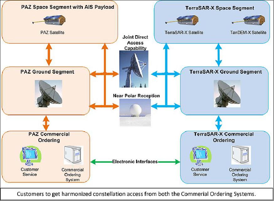
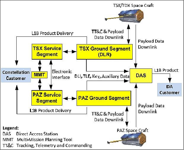
Ordering and delivery: A scheme describing the main blocks of the systems, and their interactions is shown in Figure 32. Airbus DS and Hisdesat, the commercial entities, manage the direct interactions with the customers. Ordering and delivery are done via either of the partner’s CS (Customer Service) team or directly by the DA (Direct Access) customer via the DAS (Direct Access Station). The MMT (Multi-Mission Planning Tool) suggests an acquisition planning taking into account both PAZ and TerraSAR, based on anticipated satellites orbit positions. Both Service Segments then check with their respective GS the feasibility of the part of the acquisition planning attributed to their satellite. Once feasibility is confirmed, the orders are passed to each GS, which in turn task their satellite accordingly. Communications between the Service Segments is ensured by electronic interfaces,such as HMA (Heterogeneous Mission Access). In the standard customer case, data reception and processing is done at the respective GS.
Delivery of data is performed electronically to the customer using the delivery mechanisms established by the respective mission. A joint pricing strategy will be established, and invoicing for data & services from both missions is done by the commercial partner that was approached by the user. - In the Direct Access case, the DAS receives and processes data from both satellites on site.
DAS (Direct Access Station): The DAS enables the direct reception and processing of SAR payload data acquired by both PAZ and TerraSAR-X. Near-real time production workflows give DA customers the shortest time possible between image acquisition and product delivery. Re-processing of image data with further processing variants or with high accuracy attitude and orbit data is also possible.
Once an order is confirmed, the appropriate TSX or PAZ Ground Segment performs the acquisition planning, timeline generation, spacecraft commanding, and provides DLI (Downlink Information), TLE (Two Line Elements), Key (Decryption Key), attitude and orbit products, and further auxiliary data to the DAS.
At the DAS, the received SAR payload data are decrypted and processed into basic products at L1B level. Consistent product quality is ensured by the joint PAZ/TerraSAR processor, developed and maintained by the DLR. The L1B product is delivered directly to the DA customer, for immediate image analysis, to perform external value-added processing or for further product distribution to the own customer group.
Modes harmonization: Acquisition modes onboard PAZ and TerraSAR will be harmonized to enable consistent constellation products and services. Both PAZ and TerraSAR images will meet the same quality criteria. In particular, interferometry analyses with joint TSX-PAZ image stacks shall be possible. The harmonization process ensures the synchronization of several parameters between both missions:
- orbit phasing between the satellites compatible with interferometry analysis (overlapping ground tracks)
- the adaptation of the space segment, in particular beams configuration
- the upgrade of the ground segment capabilities: image commanding and relevant antenna parameters.
Applications such as visual interpretation, surface deformation monitoring and ship detection will significantly benefit from these upgrades. Besides the StripMap, ScanSAR and SpotLight modes, the Wide ScanSAR and Staring SpotLight will also be harmonized. The latter two modes were recently implemented on TerraSAR-X and TanDEM-X to extend the sensors’ capabilities with respect to coverage and resolution. Wide ScanSAR, particularly adapted to maritime monitoring services, will profit from a very large image swath (up to 270 km, 40 m resolution). The Staring SpotLight mode will feature an unprecedented spatial resolution (down to 0.25 m), ideal for object detection and identification. Both modes will be available on TerraSAR for commercial operations from mid-October 2013 onwards.
Application examples: The benefits of a constellation of SAR satellites are manifold, as a constellation provides a larger coverage, higher system capacity, increased revisits, and higher system reliability, than a single spacecraft. Two conditions are necessary to perform InSAR (Interferometric SAR) measurements): harmonized modes and the same orbit plane with specific phasing of the satellites. Amongst the phasings compatible with InSAR, 32.73º is currently envisaged to optimize the distribution of revisit opportunities across a cycle.
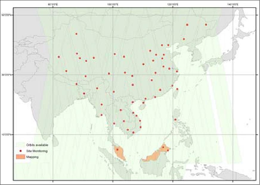
• Site Monitoring – revisit analysis: An operational scenario was assumed, to monitor 56 different sites (cities, critical infrastructure) across China and South-East Asia, between the equator and 50° N. Two use cases were studied:
- repeat pass: same incidence angle for InSAR
- maximum revisit: as often as possible.
• Interferometric repeat pass: To efficiently monitor fast evolving sites, a revisit rate lower than a week is sometimes necessary. This can be achieved by the PAZ-TerraSAR constellation, as acquisition opportunities are doubled over a dedicated period. Assuming the above mentioned phasing, acquisition opportunities are well distributed throughout the 11 days cycle: t0 with TSX, t0+5 days with PAZ and t0+11 days again with TSX.
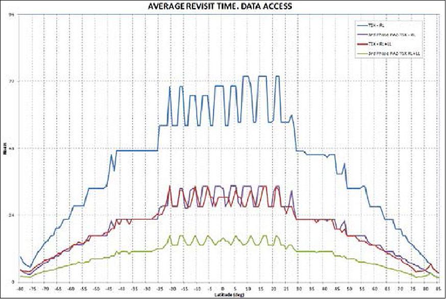
• Maximum revisit: For the use case of maximum acquisition possibilities (regardless of orbit direction and incidence angle), Figure 33 shows the results of TSX alone and TSX/PAZ constellation for the 56 test sites. Depending on the orbit footprint intersection and the latitude, the revisit times for TSX nominal right looking mode are between 44 and 88 hours, whereas the average is around 67 hours. The constellation reduces the revisit times of the selected locations significantly. The minimum revisit time in right looking mode is 26 hours, the maximum 44 hours with an average of 33 hours. Revisit times below 1 day in average can even be reached, using right and left looking modes for both satellites.
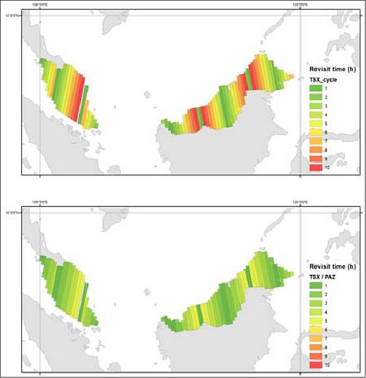
• Mapping – coverage analysis: In terms of mapping, the scenario assumptions are to cover an area of interest (say, Malaysia) in the most efficient manner. As described on Figure 34, the selected acquisition strategy includes one orbit direction, and strips of similar geometry (i.e. with moderate incidence angle differences between adjacent strips). A strategy that would combine both ascending and descending acquisitions would not reduce the overall coverage time, but increase the complexity of the mosaic production.
For this area of interest 18 orbits in total are available for TSX and 36 for the TSX/PAZ constellation, with a potential acquisition capacity per 11 day cycle of 3600 s or 7200 s, respectively (in right looking mode). Based on the additional acquisition capacity of PAZ, the time for covering the area is reduced from 3.6 (10 cycles) to 1.8 month (5 cycles), as described in Table 5. Beside the reduction of coverage time, also the potential conflicts with other acquisitions (e.g. site monitoring use case) are reduced thanks to the doubled potential capacity.
Parameter | TSX | TSX/PAZ |
Total orbits available | 9 ascending / 9 descending | 18 ascending / 18 descending |
Potential total capacity per cycle without any constrains | 3600 seconds | 7200 seconds |
Cycles needed for full coverage | ~ 10 (3.6 months) | ~ 5 (1.8 months) |
• Surface deformation monitoring: One application that will significantly benefit from the constellation increased revisit is interferometric surface deformation monitoring. As mentioned above, harmonization of the modes will allow the construction of joint image stacks. The precision of interferometric techniques such as InSAR is directly related to the temporal density of the data stacks, and can reach the cm to mm level. In summary, the constellation benefits for interferometry analyses will be:
- Lower temporal decorrelation
- Improved sensitivity for fast movements (e.g. triggered landslides). The problem of unwrapping bias is reduced.
- More reliable atmospheric correction
- Less impact of potential data gaps in temporal stack, e.g. due to acquisition conflicts.
Outlook and summary
The PAZ-TerraSAR constellation is planned to be operational shortly after the PAZ spacecraft launch, in late 2017. This will be the blue print of a first of its kind CCC (Coordinated Constellation Concept) amongst X-band SAR satellites. This scalable concept will enable further satellite programs to join PAZ and TerraSAR, for the mutual benefit of users, public and commercial partners alike. It shall particularly raise interest of nations intending to set-up a SAR Earth observation program. It allows the sharing of risks and benefits between partners, each of whom is responsible for a part of the constellation.
References
1) Eva Vega, Juan Ureña, “Ingenio and PAZ Ground Segment Interoperability,” GSCB (Ground Segment Coordination Body) Workshop, June 18-19, 2009, ESA/ESRIN Frascati, Italy, URL: http://earth.esa.int/gscb/papers/4.6_Urena.pdf
2) J. Lomba, R. Trigo, J. Ureña, E. Vez, M. López, F. Cerezo, M. Fernández, A. Borges, J. Sánchez-Palma, “The Spanish Earth Observation Program,” Proceedings of the 2nd Workshop on Advanced RF Sensors and Remote Sensing Instruments 2009, Noordwijk, The Netherlands, Nov. 17-18, 2009
3) Mónica López, “Spanish Earth Observation Programme,” 2008, URL: https://www.cdti.es/recursos/doc/Programas/Aeronautica_espacio_retornos_industriales
/Agencia_Espacial_Europea/1245_251125112008103422.pdf
4) Fernando Cerezo, “HISDESAT: PNOTS operator,” Space Week May 2011, Madrid, Spain, URL: ftp://130.206.92.88/Espacio
/Mesa%20Redonda%201%20-%20E11%20-%20HISDESAT%20-%20Fernando%20CEREZO.pdf
5) “The Paz satellite: a defense and security solution provided by Astrium España,” Feb. 2, 2009, URL: [web source no longer available]
6) EADS-CASA Espacio, June 2012 , URL: http://www.ubifrance.com/medias/document/ece-2012-06-ing_13_12_2012_17_17.pdf
7) Frank Döngi, “Earth Observation from Space - The European Landscape in the Second Decade,” SPIE Remote Sensing, Sept. 19, 2011, Prague, Czech Republic, URL: http://spie.org/Documents/AboutSPIE/PDF/ERS11-plenary-Doengi.pdf
8) P. Saameno, J. Closa, M. Labriola, J. Sanchez, A. Solana, F. López Dekker, A. Garcia Mondejar, A. Broquetas Ibars, “Radiometric Budget Characterization of X-band SAR instrument on-board PAZ,” Proceedings of the 2nd Workshop on Advanced RF Sensors and Remote Sensing Instruments 2009, Noordwijk, The Netherlands, Nov. 17-18, 2009
9) “Astrium officially presents the PAZ satellite in Spain,” Astrium, June 7, 2011, URL: [web source no longer available]
10) Matt Ford, ”Elon Musk's SpaceX to launch Spain's first military spy satellite,” EuroWeekly News, 10 Feb. 2018, URL: https://www.euroweeklynews.com/news/on-euro-weekly-news/spain-news-in-english
/1471561-elon-musk-s-spacex-to-launch-spain-s-first-military-spy-satellite
11) Stephen Clark, ”Launch Schedule, 'Falcon 9, PAZ,” Spaceflight Now, 9 Feb. 2018,URL: https://spaceflightnow.com/launch-schedule/
12) ”Spain's First ... PAZ Radar Earth Observation Satellite is Shipshape and Ready to Ship,” Satnews Daily, 22 Nov. 2017, URL: https://www.satnews.com/story.php?number=842808427
13) ”Hisdesat announces window launch of PAZ Satellite,” Hisdesat, Nov. 2017, URL: http://www.hisdesat.es/eng/noticias_notas.php?id=163
14) Sahil Suri, Katja Bach, Vinyas Brahmappa, Selin Parlar, Alexander Kaptein, Fernando Cerezo, Miguel Angel Serrano, Miguel Angel Garcia Primo, “TerraSAR-Paz Constellation: Collaboration, innovation and a blue print for the future,” Proceedings of the 65th International Astronautical Congress (IAC 2014), Toronto, Canada, Sept. 29-Oct. 3, 2014, paper: IAC-14.B1.1.10
15) “Successful integration of the PAZ satellite by Astrium,” Astrium Press release, Sept. 17, 2013, URL: [web source no longer available]
16) ”Airbus-Built PAZ Satellite Pushed to Orbit for Hisdesat by SpaceX,” Satnews Daily, 22 Feb. 2018, URL: http://www.satnews.com/story.php?number=1085928957
17) Caleb Henry, ”SpaceX launches pair of its demo internet satellites with Spanish radar satellite,” Space News, 22 Feb. 2018, URL: http://spacenews.com
/spacex-launches-pair-of-its-demo-internet-satellites-with-spanish-radar-satellite/
18) Matt Williams, ”SpaceX Launches the First of Thousands of Space Internet Satellites, but Didn’t Quite Catch the Fairing,” Universe Today, 22 Feb. 2018, URL: https://www.universetoday.com/138621
/spacex-launches-first-thousands-space-internet-satellites-didnt-quite-catch-fairing/
19) ”Hisdesat Brings in SpaceX to Send Their PAZ Satellite to Orbit,” Space news Daily, March 15, 2017, URL: http://www.satnews.com/story.php?number=1762969161
20) ”Hisdesat Commits Launch of PAZ Satellite to SpaceX,” Hisdesat, March 7, 2017, URL: http://www.hisdesat.es/eng/noticias_notas.php
21) Caleb Henry, ”Hisdesat demanding refund as it dumps Dnepr for Falcon 9,” March 13, 2017, URL: http://spacenews.com/hisdesat-demanding-refund-as-it-dumps-dnepr-for-falcon-9/
22) ”PAZ to extend Airbus radar satellites constellation for improved monitoring capabilities by end of 2017,” Airbus DS, Press Release, March 21, 2017, URL: https://airbusdefenceandspace.com/newsroom
/news-and-features/paz-to-extend-airbus-radar-satellite-constellation-for-improved-monitoring-capabilities-by-end-of-2017/
23) ”Airbus and Hisdesat successfully processed the first TerraSAR-X / PAZ Radar Interferogram,” Airbus, 28 February 2019, URL: https://www.intelligence-airbusds.com/en
/8844-airbus-and-hisdesat-successfully-processed-the-first-terrasar-x-paz-radar-interferogram?deliveryName=DM5581
24) ”exactEarth AIS Payload on the PAZ Radar Satellite is Now Live,” Space Daily, 10 December 2018, URL: http://www.spacedaily.com/reports
/exactEarth_AIS_Payload_on_the_PAZ_Radar_Satellite_is_Now_Live_999.html
25) ”Hisdesat's PAZ Spanish 'Spy' Satellite Enters into Service,” Satnews Daily, 19 September 2018, URL: http://www.satnews.com/story.php?number=1999792940
26) ”HisdeSat Image Gallery,” URL: https://www.hisdesat.es/en/multimedia_imagenes/
27) The information and the following two images of Figures and were provided by Basilio Garrido of Hisdesat.
28) Katja Bach, Hanjo Kahabka, Fernando Cerezo, Juan Ignacio Cicuendez Pérez, ”The TerraSAR-X / PAZ Constellation: Post-Launch Update,” EUSAR 2018, (12th European Conference on Synthetic Aperture Radar), Aachen, Germany, June 4-7, 2018
29) Information provided by Andreas Ohndorf of DLR/GSOC.
30) Mike Wall, ”SpaceX's Prototype Internet Satellites Are Up and Running,” Space.com, 22 Feb. 2018, URL: https://www.space.com/39785-spacex-internet-satellites-starlink-constellation.html
31) M. Labriola, J. M. González Arbesú, J. Romeu Robert, I. Calafell Rueda, J. Sánchez Palma, P. Saameño Pérez, J. Closa Soteras, A. Solana González, “AMOR: an Antenna MOdeleR for the Spanish SAR Satellite (PAZ),” Proceedings of the 2nd Workshop on Advanced RF Sensors and Remote Sensing Instruments 2009, Noordwijk, The Netherlands, Nov. 17-18, 2009
32) ftp://130.206.92.88/Espacio
/Mesa%20Redonda%201%20-%20E10%20-%20ECE%20-%20Gonzalo%20GALIPIENSO.pdf
33) Fernando Monjas Sanz, Maria Isabel Martín Hervás, “Dual Polarized Subarray For Spaceborne SAR at X-BAND,” 3rd European Conference on Antennas and Propagation (EuCAP 2009), Berlin, Germany, March 23-27, 2009
34) J. Sánchez Palma, A. Solana González, I. Martín Hervás, F. Monjas Sanz, M. Labriola, J. Martínez Cengotitabengoa, F. M. García Molleda, S. Moreno Aguado, P. Saameño Pérez, J. Closa Soteras, V. Bautista Juzgado,” SAR Panel Design and Performance for the PAZ Mission,” Proceedings of EUSAR 2010, 8th European Conference on Synthetic Aperture Radar, June 7-10, 2010, Aachen, Germany
35) A. Zurita, A. Solana and the PAZ Team, “SEOSAR/PAZ Mission: Panel Design and Performance,” ESA Earth Observation Summer School 2010, ESRIN, August 2010, URL: https://web.archive.org/web/20210414205714/https://earth.esa.int/documents/973910/1007971/236.pdf
36) Fernando Monjas, Isabel Martín, Andrés Solana, Antonio Montesano, Luis Cuesta, Israel Madrazo, Irene Sánchez, “X-band SAR Antenna for SEOSAR/PAZ Satellite,” Proceedings of the 32nd ESA Antenna Workshop on Antennas for Space Applications, Noordwijk, The Netherlands, Oct. 5-8, 2010, URL: https://web.archive.org/web/20140908140716/http://utopia.duth.gr/~iaitidis/ESA%20conference%202010/Papers/session%207/FCXNL-10C09-1992775-1-1992775monjas.pdf
37) B. Gómez, M. J., González, Benjamín, Braeutigam, Eva, Vega, Marcos García, Nuria, Casal, Javier, del Castillo, Juan M., Cuerda, Nuria, Alfaro, Victorina, Álvarez, “PAZ Mission: CALVAL Centre Activities,” Proceedings of EUSAR 2012 (9th European Conference on Synthetic Aperture Radar), Nuremberg, Germany, April 23-26, 2012
38) Beatriz Gomez, Juan Manuel Cuerda Munoz, Javier del Castillo Mena, Maria Jose Gonzalez, Nuria Casal, Nuria Gimeno Martínez, Patricia Cifuentes Revenga, Adolfo López Pescador, Juan Francisco Cores Muradas, Marcos García Rodriguez, “PAZ SAR System Validation Plan,” Proceedings of EUSAR 2014 (10th European Conference on Synthetic Aperture Radar), Berlin, Germany, June 3-5, 2014
39) Juan I. Cicuéndez, “The PAZ satellite: data fusion capabilities for Maritime Surveillance from Space,” Maritime Surveillance from Space, December 6,2012 , IET London, Savoy Place
40) “Description of the ROHPP Project,” URL: http://aliga.ieec.uab.es/en/en/view_project.php?PID=82
41) Estel Cardellach, “ROHP-PAZ: Polarimetric GNSS Radio Occultations with the Spanish PAZ Mission,” OPAC 2010 (Occultations for Probing Atmosphere and Climate) Graz, Austria, Sept. 6-11, 2010, URL: http://www.uni-graz.at/opac2010/pdf_presentation/opac_2010_cardellach_estel_presentation68.pdf
42) Estel Cardellach, Ramon Padulles, Sergio Tomás, Santi Oliveras, Antonio Rius, Manuel de la Torre-Juárez, Joseph Turk, Chi Ao, Robert Kursinski, Bill Shreiner , Dave Ector, Lidia Cucurull, Jens Wickert, “The new polarimetric radio-occultation mission aboard PAZ LEO for atmospheric and precipitation sounding,” Proceedings of the IGARSS (International Geoscience and Remote Sensing Symposium) 2015, Milan, Italy, July 26-31, 2015
43) Chris McCormick, “Teamed with GeoOptics for CICERO (Community Initiative for Continuation of Earth Radio Occultation),” January 2010, URL: http://lasp.colorado.edu
/~bakerd/files/McCormick-Commercial-Space-04-01-2010.pdf
44) http://www.gfz-potsdam.de/en/research/organizational-units/departments-of-the-gfz
/department-1/global-geomonitoring-and-gravity-field/topics
/development-operation-and-analysis-of-gravity-field-satellite-missions/satellite-payload-development-and-integration/laser-reflectors-for-leo-satellites/
45) M. J. González, E. Vega, B. Gómez, J. M. Cuerda, “The Ground Segment of PAZ Mission,” Proceedings of EUSAR 2012 (9th European Conference on Synthetic Aperture Radar), Nuremberg, Germany, April 23-26, 2012
46) María José González Bonilla, Nuria Alfaro Llorente, Eva Vega Carrasco, Beatriz Gómez Miguel, Marcos García Rodríguez, “PAZ Ground Segment Design and Status,” Proceedings of EUSAR 2014 (10th European Conference on Synthetic Aperture Radar), Berlin, Germany, June 3-5, 2014
47) María José González Bonilla, Marcos García Rodríguez, Eva Vega Carrasco, “PAZ Ground Segment Operation al Concept,” Proceedings of EUSAR 2014 (10th European Conference on Synthetic Aperture Radar), Berlin, Germany, June 3-5, 2014
48) “Paz ground segment,” INTA, May 31, 2011, URL: ftp://130.206.92.88/SAR/2.4%20SAR%20Vega.pdf
49) Peter B. de Selding, “Indra Nabs Contract for PAZ Ground Control System,” Space News, Nov. 28, 2011
50) http://www.indracompany.com/en/prensa/actual-indra/edition/2011/12
51) Daniel Carrasco, Victoriano Moreno, Emilio Viedma, “Ingenio and Paz Ground Segments,” 3rd GSCB (Ground Segment Coordination Body) Workshop, 2012, ESA/ESRIN, Frascati, Italy, June 6-7, 2012, URL: http://earth.esa.int/gscb/papers/2012/25-Ingenio_PAZ_ground_segment.pdf
52) Adrien Muller, Katja Bach, Noémie Bernede, Ralf Düring, Berthold Jäkle, Wolfgang Koppe, Oliver Lang, Sahil Suri, Thomas Schrage, Fernando Cerezo, Juan Ignacio Cicuendez Perez, Miguel Angel Garcia Primo, Basilio Garrido, Miguel Angel Serrano, “PAZ and TerraSAR-X Constellation, Innovation through International Cooperation,” Proceedings of the 64th International Astronautical Congress (IAC 2013), Beijing, China, Sept. 23-27, 2013, paper: IAC-13-B1.1.4
53) “TerraSAR-X & PAZ Constellation,” Astrium, April 2012, URL: http://www.astrium-geo.com/na/3126-terrasar-x-paz-constellation
54) “Astrium and Hisdesat to establish radar satellite constellation to improve coverage and access,” Space Daily, April 30, 2012, URL: http://www.spacedaily.com/reports/Astrium_and_Hisdesat_
to_establish_radar_satellite_constellation_to_improve_coverage_and_access_999.html
55) “Astrium and Hisdesat to establish radar satellite constellation to improve coverage and access,” EADS, April 24, 2012, URL: http://www.eads.com/eads/int/en/news/press.20120424_astrium_hisdesat.html
56) Sahil Suri, Katja Bach, Oliver Lang, Jürgen Janoth, Wolfgang Koppe, Fernando Cerezo, Juan Ignacio Cicuendez Perez, Miguel Angel Garcia Primo, Basilio Garrido, Miguel Angel Serrano. “TerraSAR-X, TanDEM-X &PAZ: A inique radar constellation on the horizon,” Proceedings of IGARSS (IEEE Geoscience and Remote Sensing Society) 2014, Québec, Canada, July 13-18, 2014
57) “TerraSAR-X & PAZ Constellation - New Radar Satellite Constellation Improves Coverage and Access,” Airbus Defence & Space, URL: http://www.astrium-geo.com/en/3085-terrasar-x-paz-constellation
58) Wolfgang Koppe, Katja Bach, Parivash Lumsdon, “Benefits of TerraSAR-X-PAZ Constellation for Maritime Surveillance,” Proceedings of EUSAR 2014 (10th European Conference on Synthetic Aperture Radar), Berlin, Germany, June 3-5, 2014
59) Thomas Schrage, Juergen Janoth, Alexander Kaptein, Noemie Bernede, Steffen Gantert, Ralf Duering, “TerraSAR-XNext Generation – Mission Overview,” Proceedings of the 64th International Astronautical Congress (IAC 2013), Beijing, China, Sept. 23-27, 2013, paper: IAC-13-B1.2.8
The information compiled and edited in this article was provided by Herbert J. Kramer from his documentation of: ”Observation of the Earth and Its Environment: Survey of Missions and Sensors” (Springer Verlag) as well as many other sources after the publication of the 4th edition in 2002. - Comments and corrections to this article are always welcome for further updates (eoportal@symbios.space).
Spacecraft Launch Mission Status Sensor Complement Ground Segment Constellation ReferencesBack to Top