PROBA-3 (Project for On-Board Autonomy-3)
Non-EO
ESA
Quick facts
Overview
| Mission type | Non-EO |
| Agency | ESA |
PROBA-3 (Project for On-Board Autonomy-3)
Spacecraft Development Status Launch Sensor Complement Ground Segment References
PROBA-3 is the third small satellite technology development and demonstration precursor mission within ESA's GSTP (General Support Technology Program) series. The primary mission objective is to demonstrate the technologies required for formation flying of multiple spacecraft in the fields of space science, Earth Observation and surveillance. This involves the in-orbit validation of these new Formation Flying (FF) techniques and technologies through a series of precision FF maneuvers, including formation acquisition, high precision pointing, reorientation, maintenance, resizing, rotation and slew.
The PROBA-3 mission concept comprises two independent minisatellites in HEO (Highly-elliptical Earth Orbit) in PFF (Precise Formation Flying) formation, close to one another with the ability to accurately control the attitude and separation of the two satellites. 1) 2) 3) 4) 5) 6) 7) 8) 9) 10) 11) 12) 13) 14) 15) 16)
The basic PROBA-3 mission objectives are summarized in the following list:
• Formation flying demonstration: The primary objective of PROBA-3 is to demonstrate and validate formation flying with high precision and to demonstrate it for future formation flying missions.
• Equipment qualification: Precision Formation Flying and efficient use of propellant calls for technology development in metrology, e.g. RF metrology systems and high accuracy optical metrology systems. The PROBA-3 mission will demonstrate these technologies to TRL 9 (Technology Readiness Level 9).
• Development, design and validation principles for formation flight: The distributed character of Formation Flying systems calls for new development, design, implementation and validation principles. PROBA 3 will contribute towards the establishment of these principles, and the development of required tools (simulators, etc.). Advanced assembly, integration and verification approach and tools. Relative dynamics experiments: PROBA-3 will incorporate 6DOF formation control with thrusters, realistic collision avoidance demonstration and rendezvous experiments.
• Guest payload: In addition to the Formation Flying experiments and demonstrations a scientific Guest Payload will be flown - a large (length about 150 m) solar Coronagraph Instrument distributed over the Formation. Using the PROBA-3 generic Formation Flying capabilities, the Formation Flying of this distributed single Virtual Instrument will constitute a convincing demonstration of Formation Flying in addition to provide scientific mission return.
Consortium of PROBA-3: The project is lead by a consortium of industrial companies in several ESA member states (in alphabetic order): DEIMOS (Spain, Portugal), EADS-CASA Espacio (Spain), GMV Space and Defence (Spain), NGC Aerospace (Canada), OHB-Sweden, formerly SSC (Sweden), QinetiQ Space NV (Belgium), SENER (Spain), Spacebel (Belgium). SENER Ingeniería y Sistemas S. A. is the designated mission prime for the CDE phase. Collaboration with CNES is under discussion between the two space agencies. The Scientific payload is proposed by the Laboratoire d’Astrophysique de Marseille (France).
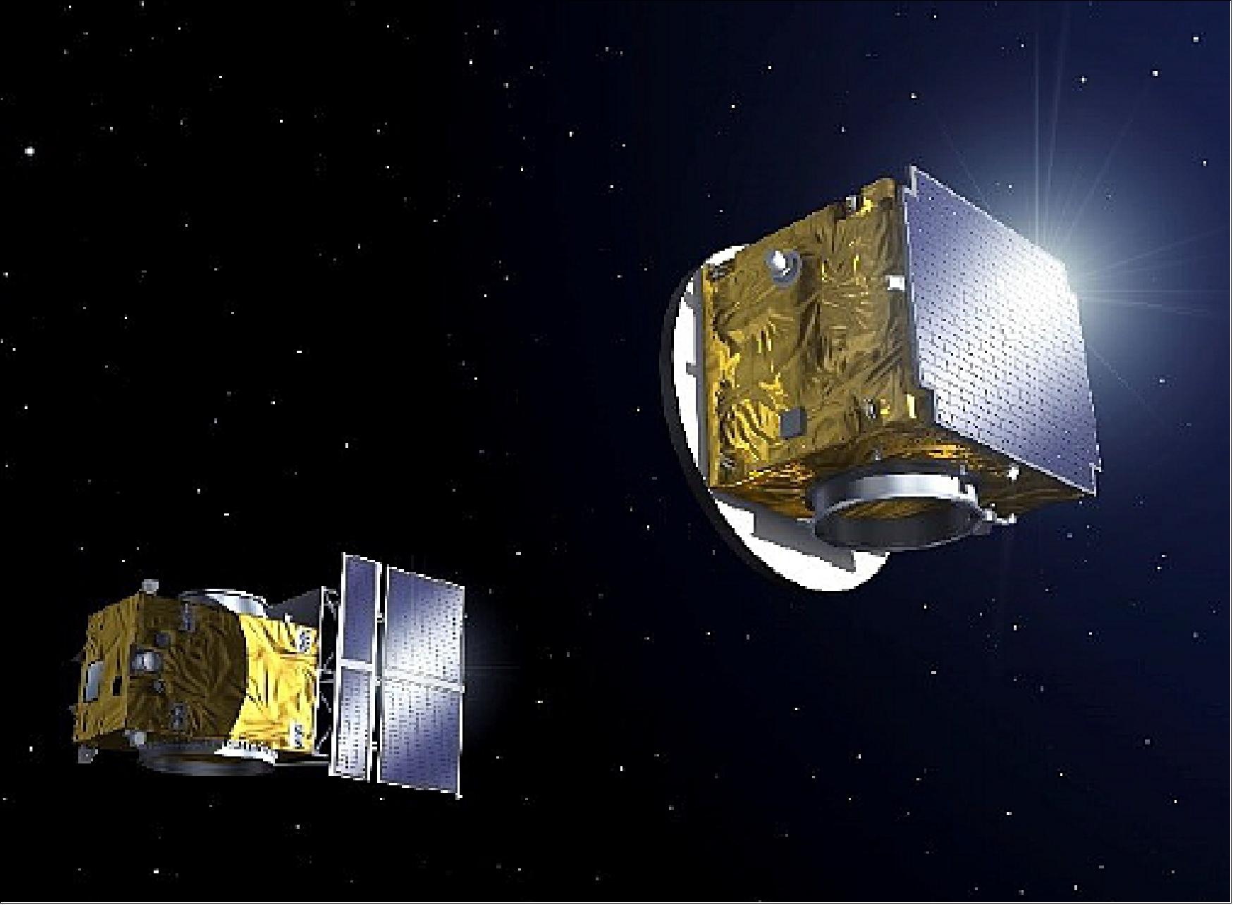
It is important to note that the PROBA-3 mission design is completely driven by the need to fulfil the FF (Formation Flying) demonstration objectives. The mission and system requirements are mainly derived by the PROBA-3 technology demonstration mission envelope, in particular the need to constrain the budget and maximize the PROBA platform reuse. Figure 1 illustrates the PROBA-3 spacecraft acquiring formation.
History
- The Phase A of PROBA-3 started in October 2006.
- During the last years PROBA-3 has evolved from the initial CDF studies at ESA, through the phase A studies, to the phase B1 and B2 reaching PDR (Preliminary Design Review)in the fall of 2012.
- PROBA-3 Phase CD/E1 proposal is in preparation and will start in Autumn 2013.
Mission Challenges
Two European missions have already collected some experience in formation operations in LEO (Low Earth Orbit).
• The DLR (German) TanDEM-X (TerraSAR-X add-on for Digital Elevation Measurement) mission is composed by two large Earth Observation satellites, of 1350 kg each, flying a SAR (Synthetic Aperture Radar) payload. The satellites were launched in June 2007 and in June 2010 , respectively, into a circular orbit of 514 km altitude. The mission uses relative GPS navigation to control the formation with typical distances between 250 and 500 m. TanDEM-X autonomously controls the formation with an accuracy of 10 m (1σ), while typical ground-in-the-loop formation accuracy is about 30 m (1σ).
• The Swedish PRISMA (Prototype Research Instruments and Space Mission technology Advancement) mission consists of two small satellites: Mango of 95 kg and Tango of 50 kg (total of ~ 145 kg). The satellites were launched in a stack configuration on June 15, 2010 into a near-circular orbit of ~725 km altitude. The mission uses relative GPS, FFRF (Formation Flying Radio Frequency) sensor and VBS (Vision Based Sensor) navigation to demonstrate different formation maneuvers from few kilometers distance, down to 2 m. The autonomous formation control, exclusively performed by the Mango spacecraft, achieved decimeter level accuracy.
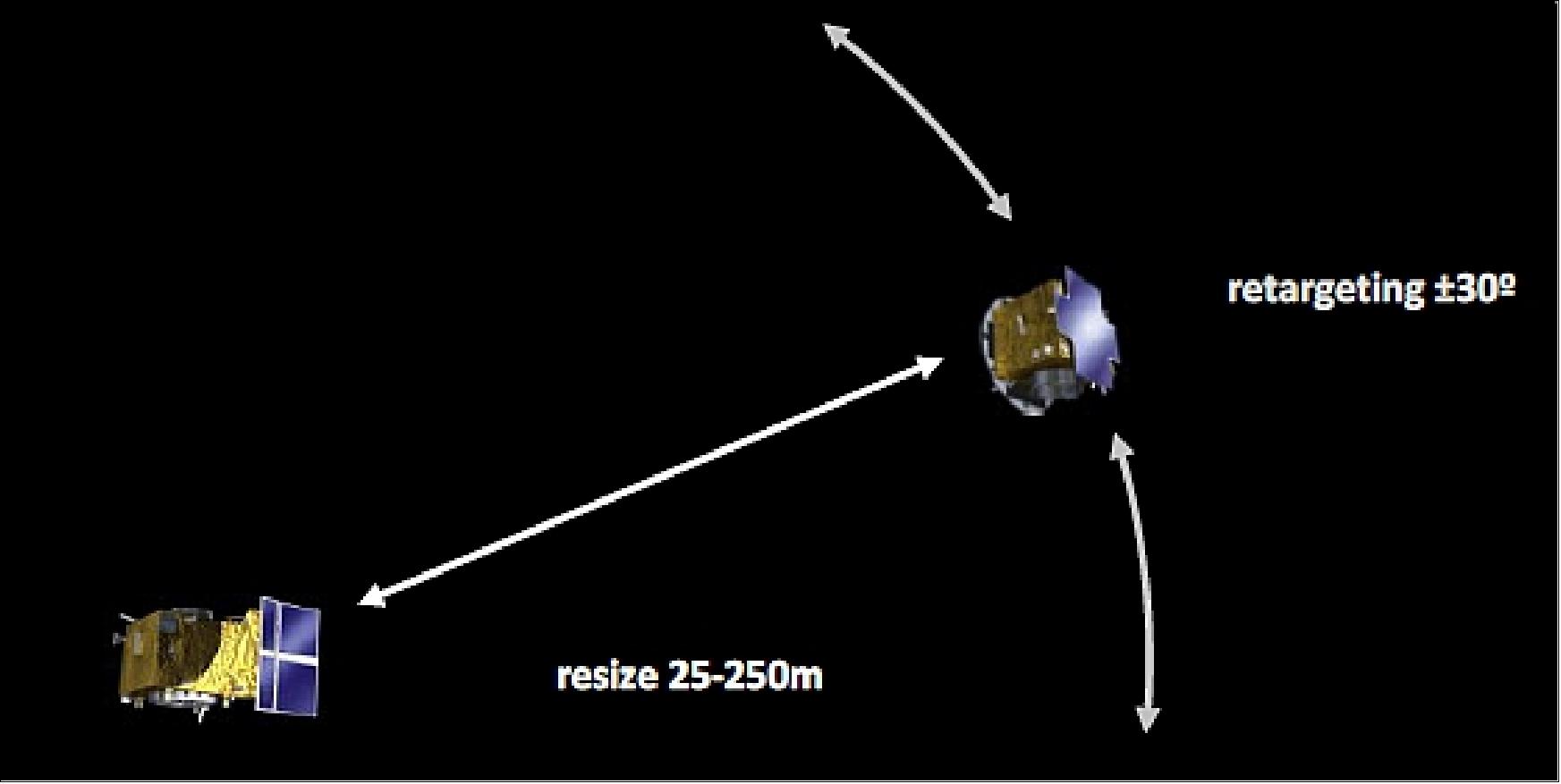
• The PROBA-3 mission is meant to go a step further and to demonstrate the Formation Flying technology that will enable virtual structure build up. The are several challenges for achieving this ambitious goal. PROBA-3 will autonomously execute a set of maneuvers with millimeter level accuracy. In particular PROBA-3 will demonstrate formation station keeping at different relative distances, from 25 m to 250 m. The mission will exercise formation resize between 25 m and 250 m, formation retargeting up to 30º and combination of station keeping, resize and retargeting maneuvers.
Mission Concept
To achieve the mission objectives, PROBA-3 is required to tackle several challenges:
• The PROBA-3 formation flying demonstration shall extend over several hours and cannot be achieved in LEO where the high gravity gradient would require high thrust authority and large propellant quantities to maintain the formation. Therefore, the two spacecraft will be launched into a HEO (Highly-elliptical Earth Orbit) and FF will be exercised during the apogee phase. Then, since formation cannot be maintained at perigee, a formation break and reacquisition is required every orbit.
• In case of off-nominal situations, the spacecraft will autonomously manage the formation and will need to take mission critical decision with no ground supervision. The satellites will not only worry about collision but also about formation evaporation. Very energetic collision avoidance maneuvers may lead in few orbits to large separation between the satellites. This separation needs to be limited otherwise excessive mission time and resources to reacquire the formation will be needed.
• During Formation Flying operation periods, GPS measurement will not be available. PROBA-3 will embark a dedicated metrology sensor suite capable of acquiring the formation and providing relative position determination with micrometric precision. The metrologies sensors’ field of view limitation, will force the spacecraft to point to the companion satellite to acquire relative navigation.
• Sun off-pointing will cause thermo-elastic deformations and periodic in flight autonomous calibration will be mandatory to compensate them.
• End-to-end formation flying verification on ground is impossible in the required formation range and in a representative environment. The PROBA-3 approach for FF performance verification is to use a dedicated software-based bench.
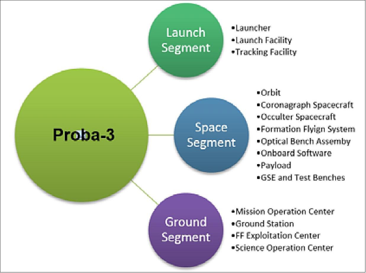
PROBA-3 mission architecture (Ref. 43): PROBA-3 includes the classical Ground, Space and Launcher segments (Figure 3), however, there are quite some specific points to consider in its architecture especially driven by the existence of a FFS (Formation Flying System). It is not physically located in any of the two satellites, but is distributed among the two satellites and in some aspects incorporates both S/Cs as elements of such Formation Flying System (Figure 3).
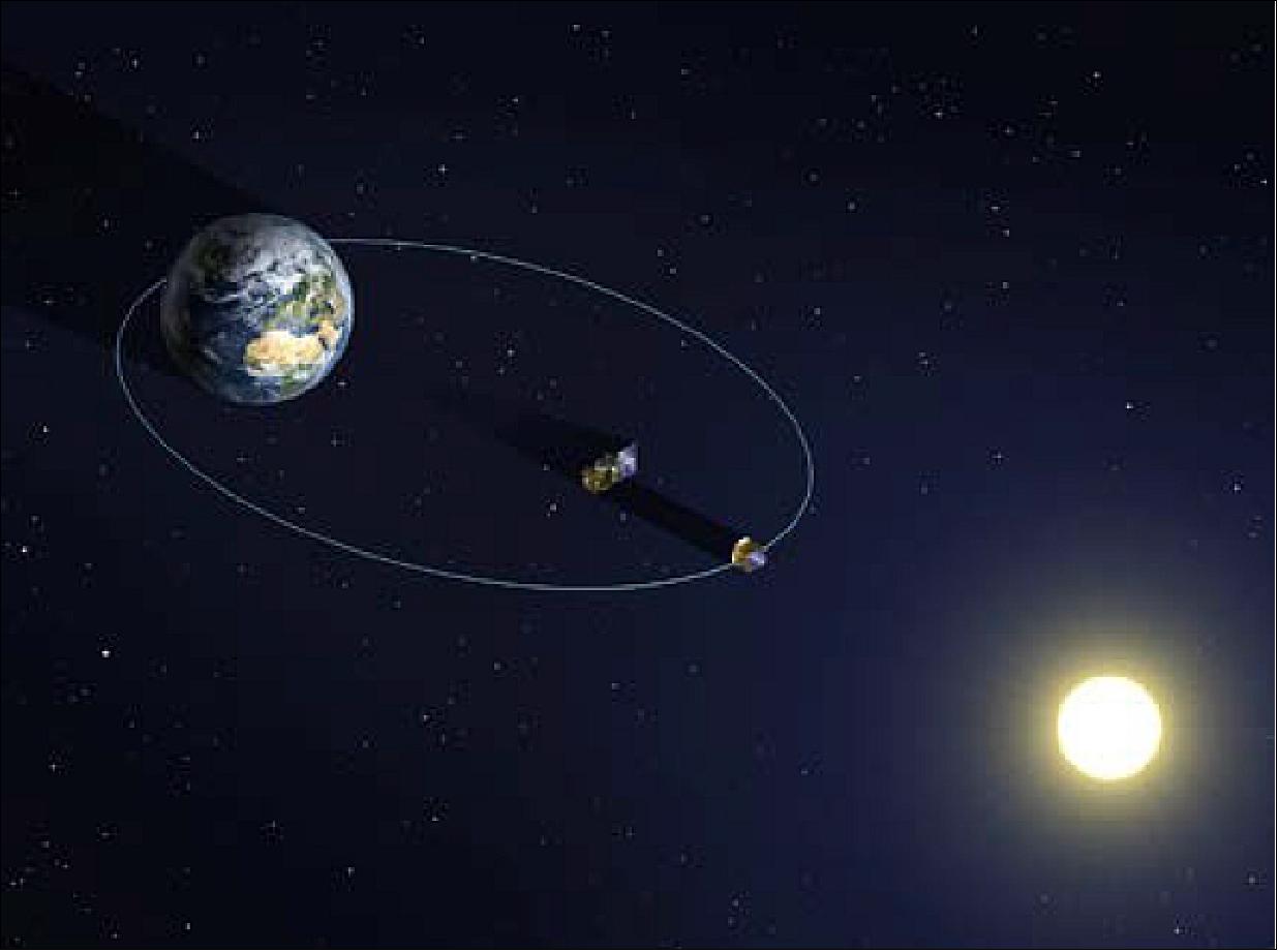
The spacecraft will be launched in stack configuration by direct injection into a highly elliptic orbit with a perigee of 600 km, an apogee of about 60,500 km and an inclination of 59º (Figure 4). The orbital period is 19.5 hours. Right ascension of ascending node, inclination and argument of perigee are selected to limit the radiation dose and to allow natural re-entry of the spacecraft after about 30 months. The selected orbit achieves also a good stability and coverage for usage of a single ground station. In a later step the two satellites are separated one from the other.
The FFS (Formation Flying System), includes the elements necessary to maintain the satellites in the desired relative configuration, and incorporates metrology equipment, control logic, SW and operation management. The FFS uses and must coordinate the two satellites, and the services included in it. One of them is the SC-GNC (developed by NGC Canada), similar to the classical AOCS, which maintains the satellites in the necessary pointing and perform delta-V maneuvers and includes several modes for allowing high accuracy inertial pointing, target pointing and safe sun pointing, implemented in both satellites.
The thermo-elastic effects on-board the spacecraft have a direct impact on the metrology systems and thus on the system’s formation flying performance. For this reason the metrology equipment of both the CSC (Coronagraph Spacecraft) and of the OSC (Occulter Spacecraft) are mounted on an OBA (Optical Bench Assembly).
Mission Profile
PROBA-3 is a complex mission involving two spacecraft that have to perform actions independently and in a coordinated way. In other more “classical” missions with a single spacecraft, the autonomous operation of the spacecraft can be organized around the AOCS modes, which somehow define the different types of activities that the spacecraft is performing, together with the payload operation within a given AOCS mode. This approach is not fully applicable to PROBA-3, considering the different levels of Formation and AOCS modes, the different spacecraft operation depending on the phase, the large variety of spacecraft maneuvers and, what is more important, that the formation flying maneuvers themselves are somehow part of the “payload” to be demonstrated (Ref. 43).
There are several satellite phases that represent the different conditions and configurations in which the spacecraft and formation evolve:
• STACK LEOP and Commissioning Phase: At the beginning of the mission, the two SC are launched together in a configuration named as “STACK”. In this configuration, OSC is mounted on top of CSC. After launcher separation, STACK will be tumbling and this needs to be stopped before other operations can take place. After this first maneuver is completed the CSC Solar Panel is deployed and afterwards the spacecraft acquires Sun attitude. Once STACK is stabilized, the commissioning of the units and algorithms are performed. During these processes, certain actions will be commanded from ground.
• Spacecraft Separation and Commissioning Phase: In this phase, STACK is separated and both CSC and OSC start flying independently. Due to the separation of the STACK, the Spacecraft are left with a relative drift velocity of 50-60 cm/s. At some point, drifting is stopped and formation enters safe relative orbit using maneuvers computed on ground. The safe relative orbit allows the spacecraft to remain at close distance (< 1 km range), without the need to control and in an inherently safe configuration. While in safe orbit, commissioning of the units and of the formation is done in order to ensure a safe execution of the formation flight. Preliminary calibration is performed to have coarse estimations of units’ alignments.
• Formation Flying Operation Phase: The Formation Flying Phase is the mission main operational phase, in which the spacecraft perform coronagraph observations and formation demonstration maneuvers. It is performed completely autonomously, only requiring the regular upload of the list of formation operations to be performed sequentially at apogee for the following 7 orbits.
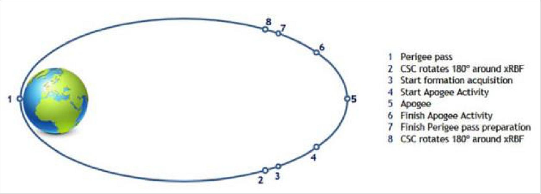
The nominal orbit activity during this phase is very varied, and several maneuvers could occur, as shown graphically in Table 1 and in Figure 5. During this phase the formation is no longer in a safe relative orbit but performing the necessary actions to keep the formation in place. Formation flying demonstration maneuvers and Coronagraphy is performed in the apogee (from point 4 to 6). Rigid formation cannot be kept during the perigee passage since the relative dynamic perturbations are very high and will cost a large amount of fuel.
True anomaly | Activity | Attitude |
0º | Perigee pass | Sun Pointing |
161º | CSC rotates 180º around xRBF | Sun Pointing |
163º | Start formation acquisition | The two S/C point towards each other Maximum sun off-point of 30º is considered. |
169º | Start Apogee Activity | Attitude depends on apogee activity. For retargeting operations a maximum sun off-pointing of 30º is foreseen. |
180º | Apogee | |
190º | Finish Apogee Activity | The two S/C point towards each other. Maximum sun off-point of 30º is considered. |
196º | Finish Perigee pass preparation | Sun Pointing |
198º | CSC rotates 180º around xRBF | Sun Pointing |
360º | Perigee pass | Sun Pointing |
Therefore, the concept is to break the rigid formation (point 7) so that during the perigee passage the two spacecraft fly uncontrolled (but inherently safe) pointing to the Sun, acquiring again the formation before the next apogee phase (point 3). The breaking and acquisition of the formation is done by performing a set of impulsive maneuvers called DTM (Direct Transfer Maneuvers). There is a DTM-1 performed at point 7 and a DTM-2 performed at point 3.
Figure 5 also shows two additional maneuvers (points 2 and 8) to rotate the spacecraft in roll while pointing to the Sun to compensate the effect of the Solar Radiation torque on the spacecraft.
After DTM-2 has finished, the system is ready to acquire formation. For this, certain maneuvers known as acquisition maneuvers are required from point 3 to point 4. During these maneuvers, the CSC and OSC would off-point from the Sun to the position in which the other S/C is expected to be.
Finally, during the apogee phase (from point 4 to point 6) the formation flying demonstration maneuvers and Sun corona observation are performed for a total of 6 h in rigid formation configuration.
Spacecraft
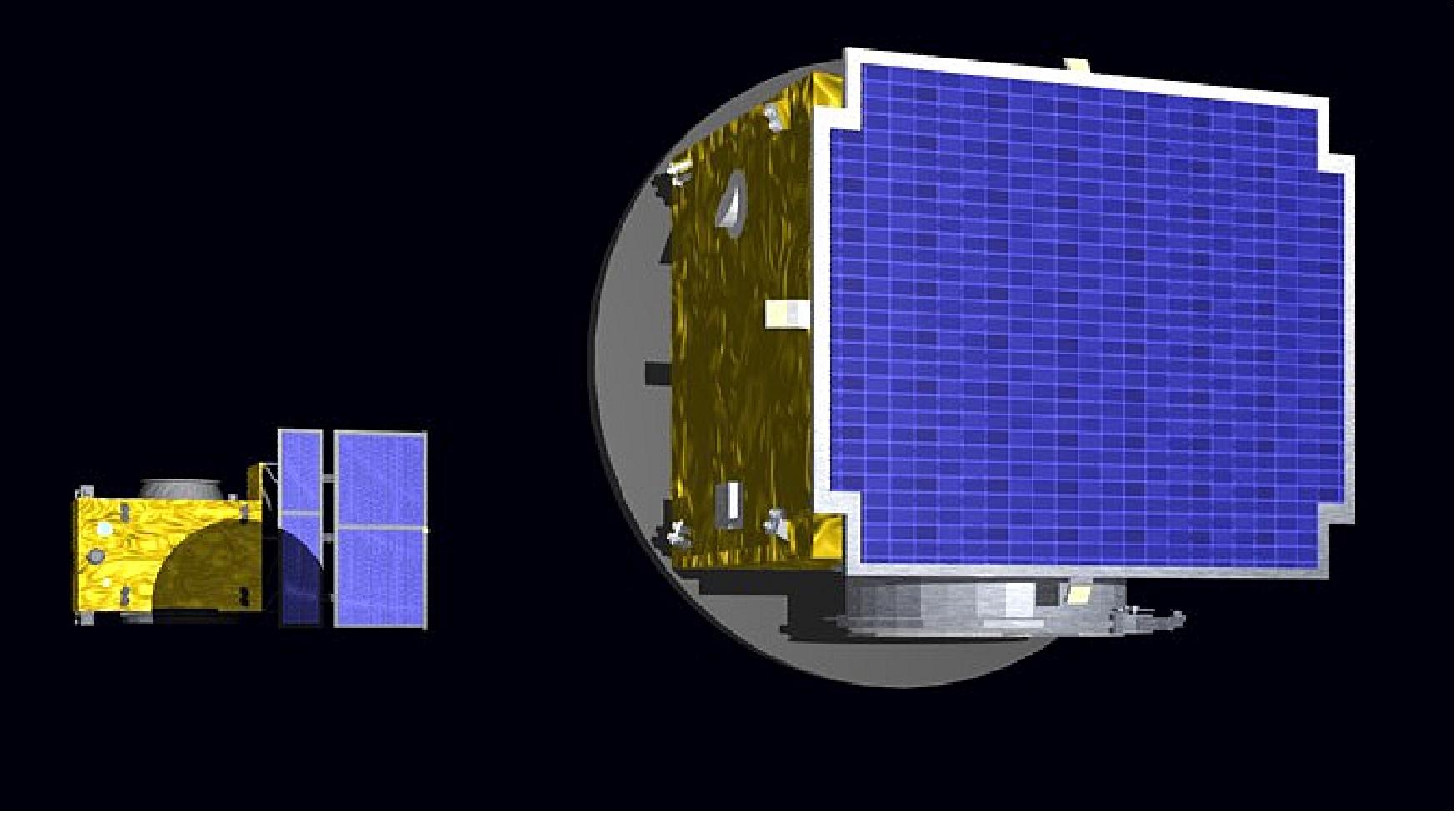
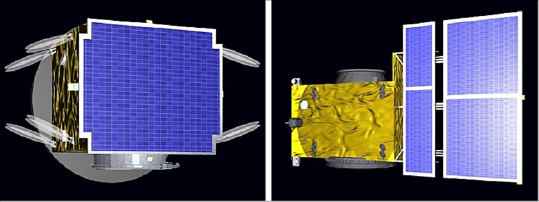
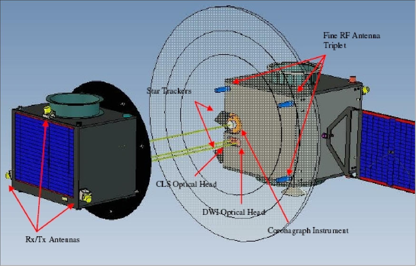
The PROBA-3 mission concept consists of two independent, three-axis stabilized minisatellites flying in a formation with relative position control accuracy of less than 1 mm. The two minisatellites are referred to as CSC (Coronagraph SpaceCraft) with a wet mass of ~300 kg and OSC (Occulter SpaceCraft) with a wet mass of ~250 kg. QinetiQ Space NV is developing one of the two satellites, the CSC (Coronagraph Sapcecraft) as subcontractor to OHB Sweden, and is providing the on-board computer for both spacecraft. 17)
The two spacecraft will be controlled in space as if they were two parts of a rigid structure (e.g. telescope optics and detector). This virtual rigid structure will be commanded to rotate and point to any desired direction. It will also be possible to set the relative distance of the two spacecraft from 25 to 250 m (i.e. change the focal length).
In order to complete the end-to-end validation of the formation flying technologies, a scientific instrument, a coronagraph, has been selected with the goal of taking pictures of the inner solar corona. The coronagraph system is distributed over the two satellites; one carrying the detector and the second one carrying the Sun occulter disk. The PROBA-3 satellites are named according to the hosted payload element: CSC and OSC.
Mission Objectives
PROBA-3 mission has the goal to demonstrate in-flight FF (Formation Flying) key technologies and obtain scientific results from a coronagraph science payload, including also dedicated rendezvous demonstration. After completion of the PROBA-3 mission, the following mission results are expected:
• Validated formation flying control algorithms. A complete FF Guidance Navigation and Control (GNC) including a set of generic FF manoeuvres and configurations will have been analysed, developed and validated in orbit. Experience will be gained in at-tempting to meet future formation flying mission performance requirements.
• Mature formation flying metrology. A set of new metrology systems will be validated in orbit in term of behaviour and performances. A complete metrology chain will be available “off the shelf” for future FF operation.
• Demonstrate formation autonomy and robustness. Autonomous FF distributed architecture will have been analysed, implemented and tested in a complete system in orbit. The safety and reliability of formation flying will have been demonstrated.
• Advanced assembly, integration and verification approach and tools. A development approach including the validation approach and an iteration of the engineering infrastructure will have been deployed and exercised. Models of the metrology units and GNC simulators will be available and correlated with their actual flight performances.
• Scientific return. Scientifically relevant coronagraph measurements will be made with performance superior to any current or past mission.
• Exercise rendezvous in high elliptic orbit. A Rendezvous experiment will be performed, which intends to demonstrate that autonomous rendezvous in a highly elliptical orbit using only 2D imagery is feasible.
• Technology experiments deployment and demonstration. PROBA-3 will incorporate technology experiments, to be flown and demonstrated in flight. These include 6DOF formation control with thrusters, realistic collision avoidance demonstration and technology payloads.
The main AOCS (Attitude and Orbit Control Subsystem) software innovation resulting from the PROBA-3 requirements is the application of the PROBA-2 AOCS software technology to a FF mission. Because PROBA-3 is a FF mission, the guidance, navigation and control function has been separated into two modules: the Formation Flying GNC (FF-GNC) software at formation flying level and the Spacecraft GNC (S/C-GNC) software at spacecraft level.
The FF-GNC software performs the navigation and guidance function, in addition to computing the control commands, for the relative position and relative attitude of the two spacecraft. The S/C-GNC software, which is being designed by NGC (NGC Aerospace Ltd.), performs the GNC function for the absolute position and absolute attitude of the individual spacecraft. In addition, the S/C-GNC software is responsible for managing the commands to the actuators at low level including, when applicable, transmitting the commands received from the FF-GNC software. The S/C-GNC software and the FF-GNC software interact with the spacecraft through the platform software. 18) 19) 20) 21) 22)
OSC (Occulter Spacecraft, Ref. 43)
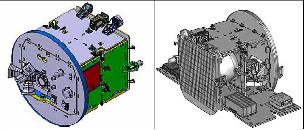
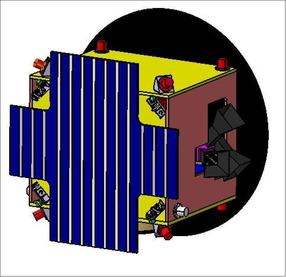
The OSC is designed to fly with the same face facing the Sun at all times. For the science operations it acts as an occulting disc, creating a stable eclipse and leaving only the solar corona visible to the Coronagraph instrument located in the CSC. OSC wet mass is about 250 kg, with a size of 1378mm x 1069 mm x 1160 mm. The Occulter spacecraft structure is essentially a cube with all the avionics and instrument equipment mounted on the inner panels, and with the occulter disc on the anti-Sun face.
The OSC is responsible for performing the high accuracy actuation formation control using cold gas milli-Newton thrusters.
CSC (Coronagraph Spacecraft)
Like the Occulter, the Coronagraph Spacecraft is designed to be always Sun pointing with the same face. CSC wet mass is about 300 kg with a size of 985 mm x 1440 mm x 1238 mm. Particular care in the design of the Solar panel layout is taken due to the fact that the Sun is partially eclipsed by the OSC during Coronagraph Operations. The design of the spacecraft is based on the asymmetric solar sail concept: a rigid support structure is used to position the single solar panel outside the penumbra. During launch, the deployable solar panel is stowed against the rigid support structure. The CSC is responsible of performing the main orbital maintenance impulsive manoeuvres with monopropellant thrusters.
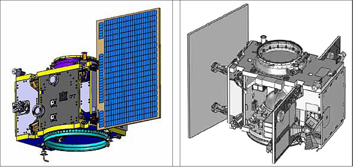
Spacecraft commonalities: The two satellites have been designed with maximum commonality in design and configurations. Both spacecraft share the same power generation and on-board data handling system. Power generation is based on Li-Ion batteries, battery regulated 28 V bus and triple-junction GaAs solar cells. Each spacecraft is equipped with the ADPMS on-board computer and power conditioning, which is the workhorse of all previous Proba spacecraft and developed by Qinetiq Space in Belgium. A passive thermal control is implemented in each spacecraft, with the use of thermistors, heaters, radiators and thermal blankets.
The spacecraft include OBA (Optical Bench Assemblies) designed for high thermal stability, including high stability sandwich panels of CFRP and aluminum core, with titanium fittings for attachment of the Units. The benches have a thermal control with heater lines in order to minimize the gradients along the bench.
Each spacecraft is 3-axis stabilized using a set of four reaction wheels. For attitude determination, a set of 3 star tracker optical heads (STR) are used. Conventional Sun sensors and gyros are used for safe modes. The configuration of formation flying units, AOCS (Attitude and Orbit Control Subsystem) sensors and actuators is presented in Table 2.
Item/Element | Item/Parameter | On OSC | On CSC |
Formation Flying Units | High Accuracy Metrology | 1 x Corner-cube | Emitter (laser) and Sensor |
VBS (Vision Based Sensor) | 8+8 x IR LEDS | 2 x WAC; 2 x NAC | |
ISL (Inter Satellite Link) System | 2 x Rx-Tx + 4 x antennas | 2 x Rx-Tx+ 4 x antennas | |
GPS | 2 x receivers + 2 x Antennas | ||
Science Equipment | Coronagraph Instrument | Optical Detector and electronics | Occulter disk |
Absolute Radiometer |
| In Sun Panel | |
AOCS | STR (Star Tracker) | 3 x Optical Heads + 2 x electronics | |
Sun sensors | 5 (1 Fine and 4 Coarse) redundant cosine sensors | ||
Rate sensors | Two 3-axes Inertial Rate Sensors | ||
Actuators | Propulsion thrusters | 2 x 8 x 1N Monopropellant | 2 x 12 x 10 mN Cold Gas |
Reaction Wheels | Pyramid of 4 units | ||
FF Technology
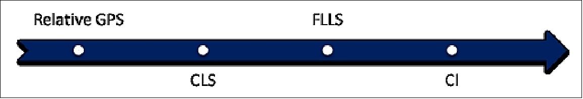
PROBA-3 will validate in orbit novel Formation Flying metrology sensors that will allow the acquisition of the metrology chain. The metrology chain consists on GPS receivers, CLS (Coarse Lateral Sensor) and FLLS (Fine Lateral and Longitudinal Sensor) to finally acquire the CI (Coronagraph Instrument).
In PROBA-3, the relative GPS sensors will be commissioned first. The way to commission it, will be to downlink the absolute GPS data of the CSC and OSC spacecrafts and calculate on ground the same solution obtained in flight. Since the solar radiation pressure coefficients are hard to estimate on ground, several orbits will be devoted to the characterization of this perturbation. Once the relative GPS is commissioned, its propagated solution will be used to commission the CLS. No maneuvers will be performed from the perigee GPS navigation to the CLS acquisition, in order to have the maximum propagation accuracy. CLS lateral measurements and GPS longitudinal measurements will be used to acquire and commission FLLS. Finally FLLS will be used to acquire and commission the CI (Coronagraph Instrument). The incremental sensor commissioning approach is depicted in Figure 9.
Coronagraph Spacecraft (CSC) hosts the CI (Coronagraph Instrument) | Occulter Spacecraft (OSC) hosts the occulting disk | ||||
Metrology | GNC sensors | GNC actuators | Metrology | GNC sensors | GNC actuators |
HAM sensor | 3 x STR (Star Tracker) | 4 x RW (Reaction Wheel) | VBS (Vision Based Sensor) | 3 x STR | 4 x RW |
CLS sensor | 6 x SAS (Sun Acquisition Sensor) | 2 x 8 N thrusters | Corner cubes | 6 x SAS | 2 x 8 mN thrusters |
ISL | 2 x Gyros |
| ISL (Intersatellite Link) | 2 x Gyros |
|
MIRES | 2 x GPS |
|
| 2 x GPS |
|
Metrology element | Operational range | Measurement accuracy (1σ) |
GPS | At perigee | 7.5 cm (at perigee), <10 m when propagated up to at apogee entry |
CLS (Coarse Lateral Sensor) | ±13 m @ 150 m (lateral) | 1 mm @150 m (lateral) |
FLLS (Fine Lateral and Longitudinal Sensor) | ±20.5 mm (lateral) | 21 µm (lateral) |
CLS (Coarse Lateral Sensor)
CLS is the second level in the chain of PROBA-3 relative metrology. The CLS allows enough LOS precision to acquire the fine/ranging metrology. The CLS working principle is the following:
1) a defocused laser beam is sent towards a corner cube located on the companion satellite
2) the laser bounce on the corner cube and is retro-reflected to the sensor lens, which images the light on a detector
3) a filter blocks all unwanted light
4) the detector captures the images
5) an electronic unit records the images and localizes the return light bright spots
6) this unit computes the centroid and forwards this information as output via a RS422 communication link.
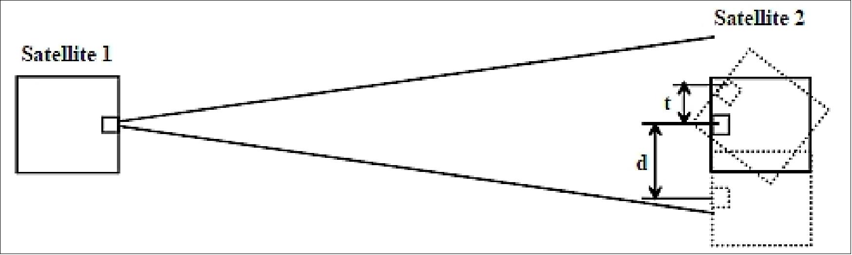
In the current specification, the attitude of the S/C will be controlled within ±10 arcsec. It is understood that the S/C will face toward each other with this accuracy. Given the typical dimensions of the PROBA-3 S/C (1 m) we can say that with this accuracy the position of a target will be controlled within a volume of 100 µm size (t<100 µm). This is negligible with respect to the millimeter accuracy level, requested for the CLS in this work.
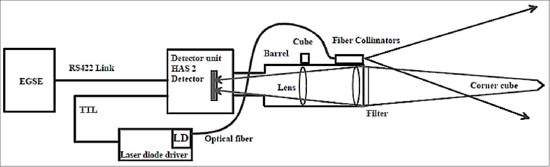
Architecture: The current CLS baseline is the instrument developed by CSL (Centre Spatial de Liège), Liège, Belgium. The lateral sensor is based on a camera (CMOS detector: Cypress HAS2 CMOS APS type detector that allows quick read-out of sub-windows of interest), a telecentric lens designed at CSL, a fiber-coupled laser-diode bar and a corner cube. 23)
The fiber-coupled laser-diode bar emits a diverging beam, from the master spacecraft to the slave spacecraft. A corner cube located on the slave spacecraft sends the light back. This light is captured by the telecentric lens and camera (built by Deltatec of Liège). A lateral shift “d” of the corner cube is seen on the camera as an image displacement. Real-time centroidization algorithms will allow tracking the image position and feed the on-board computer with this information via a RS422 link, allowing further position stabilization. The imaging system is adjusted and designed for a depth of field from 25 m to 250 m.
The CLS is based on the following architecture:
• A corner cube (50 mm diameter) which is the target on the OSC (Occulter Spacecraft)
• A CLS telescope unit containing a barrel, lens(es), Interference filter, neutral Density Filter, Alignment Cube. The CLS telescope unit is composed of 5 lenses, 2 filters, an alignment cube and a divergent lens.
• A CLS detector unit based on a Cypress HAS2 CMOS APS detector
• The centroid data is downloaded via a RS422 link to an EGSE (Electrical ground support equipment)
• The laser diode driver is controller via the detector unit
• The laser diode itself is a fiber optic pump laser diode (Instantaneous Optical Power 40 W) attached to a fiber collimator/NA converter.
Because of the large depth of operation, all lateral system performances are angular ones. The system requires:
- Tracking capability for a spot moving @ 0.5 arcdeg/s in the field of view of the camera.
- Spot detection with the sun (bright source) in the field of view
- Centroidization accuracy: 0.1 camera pixels (3.5 arcsec)
- Absolute calibration accuracy: 0.14 camera pixels (5 arcsec).
The system is a standalone unit. Once connected to an unregulated 28 V power-supply, it delivers, after spot detection, pixel coordinates to the RS422 link at a 10 Hz rate. Its average power consumption is < 8 W. The system can be put in a programming mode, to allow uploading settings in the camera. Tracking, absolute calibration, resolution and sun avoidance have been measured in a field of 10 arcdeg and the range of depth of 5 m to 80 m.
Optical design: The system operates as an angle to position converter. The angular accuracy requirement is 5 arcsec in a FOV of 10 arcdeg. The 10 arcdeg are imaged on a 1024 x 1024 HAS detector (18 µm pixel). The system is telecentric in the image plane (Figure 3). The NDF (Neutral Density Filter) and interference filter (IF) are placed as first components. Putting the NDF as first lens will act as a cold filter, and in this way, reduces the thermal load on the CLS.
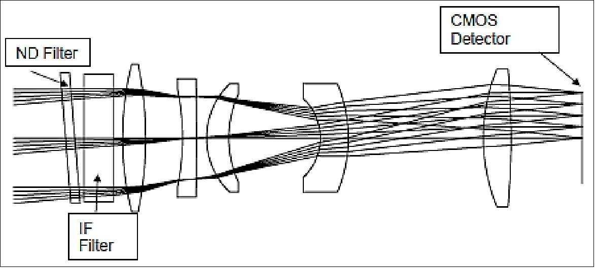
The coarse lateral sensor is a stand-alone detection system, which provides automatic coordinates of the image of a corner cube even with the sun in the field of view. The system operates in a narrow band around 980 nm.
FLLS (Fine Lateral and Longitudinal Sensor)
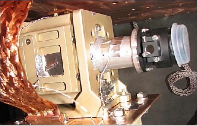
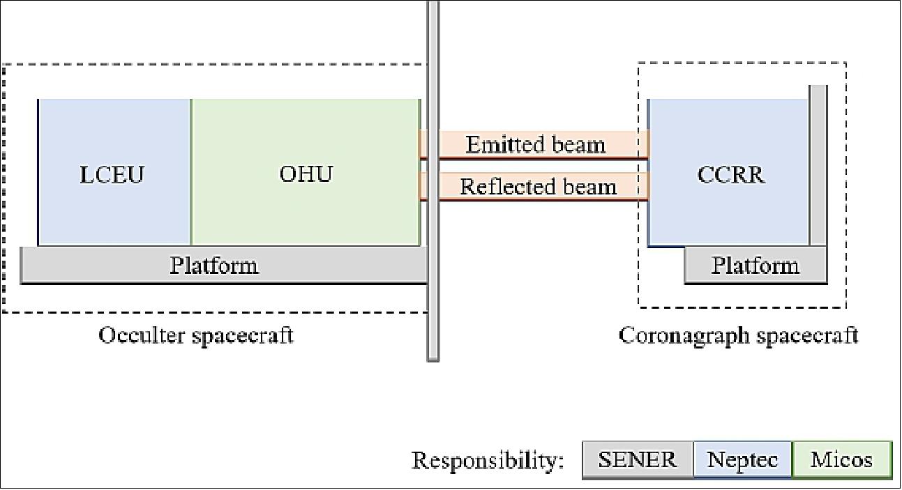
The measurement of the displacement between the two spacecraft is provided by FLLS. This instrument is being built by Neptec UK (NUK) and Neptec Design Group Canada (NDG), in collaboration with Micos Engineering GmbH. SENER is the mission prime, and is building the two spacecraft buses. FLLS comprises three sub-assemblies: the LCEU (Laser Control Electronics Unit), the OHU (Optical Head Unit), and the CCRR (Corner Cube Retroreflector). These sub-assemblies are shown in Figure 15. 24)
LCEU (Laser Control Electronics Unit) contains a 980 nm continuous-wave laser diode and signal processing electronics. The LCEU is coupled to the OHU (Optical Head Unit), which is designed and built by Micos. The LCEU and the OHU are mounted as one unit on the occulter spacecraft.
The OHU collimates and expands the beam before reflecting it out of the FLLS component on the occulter spacecraft. By collimating the beam it remains approximately the same diameter upon return to the OHU, allowing the beam to pass back through the same optical assembly. The OHU also contains the two detectors FLLS uses for analysis of the beam once it has returned from the CCRR.
The CCRR is mounted on the coronagraph spacecraft and captures the laser beam, returning it back into the OHU. The return signal is processed by the LCEU. The individual details of each component will not be described in this paper, which instead focuses on the performance of the complete sensor.
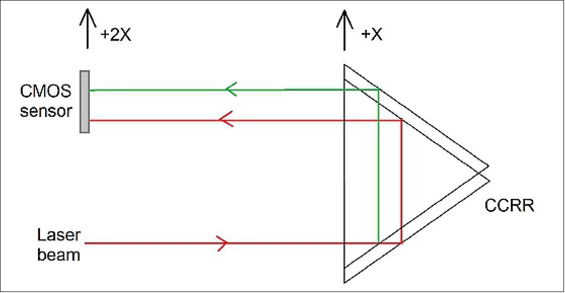
Two Measurement Systems: FLLS comprises two measurement systems – a lateral system and a longitudinal system – which work independently of one another. The lateral system is based on previous NDG heritage, from CAMS ( Canadian Metrology System). 26) This system uses a CMOS sensor to image lateral movement (Z, Y) of the returning beam, tracking the movement of the beam centroid as the CCRR moves in the Z-Y plane.
The longitudinal system sensor is a photodiode that measures the return beam intensity. An amplitude-modulated signal is added to the beam, and synchronous demodulation is used to measure its phase against an internal reference beam. This phase difference is in turn used to compute the longitudinal displacement as the CCRR moves in the X direction. The LCEU converts the lateral and longitudinal signals into a 3D displacement.
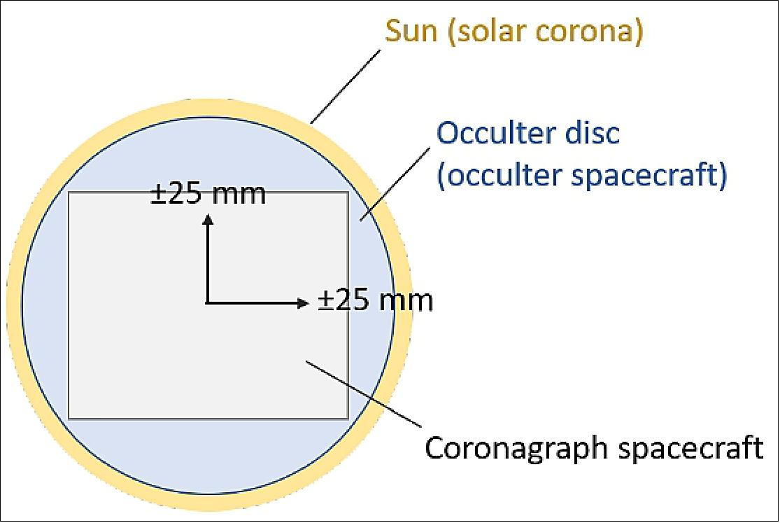
The displacement that is measured by FLLS is that of the CCRR, and therefore the coronagraph spacecraft, with respect to the occulter spacecraft. The coronagraph measurement configuration requires a fixed inter-satellite distance of 150 m (TBC). However, the two spacecraft can be between 25 m and 250 m apart during the formation flying configuration. The coronagraph spacecraft can move up to ±25 mm along the Z and Y axes, with respect to its nominal central position, as shown in Figure 16. This is to allow optimization of the coronagraph spacecraft position, and thus of the coronagraph data.
The use of a retroreflector to return the beam to the sensor means that the displacement observed on the lateral sensor is twice the actual beam displacement (Figure 17). The longitudinal system is not affected by this. However, use of the CCRR also means FLLS is impervious to tilt of the spacecraft (up to a certain angle), because any light entering the CCRR will be reflected at the same angle.
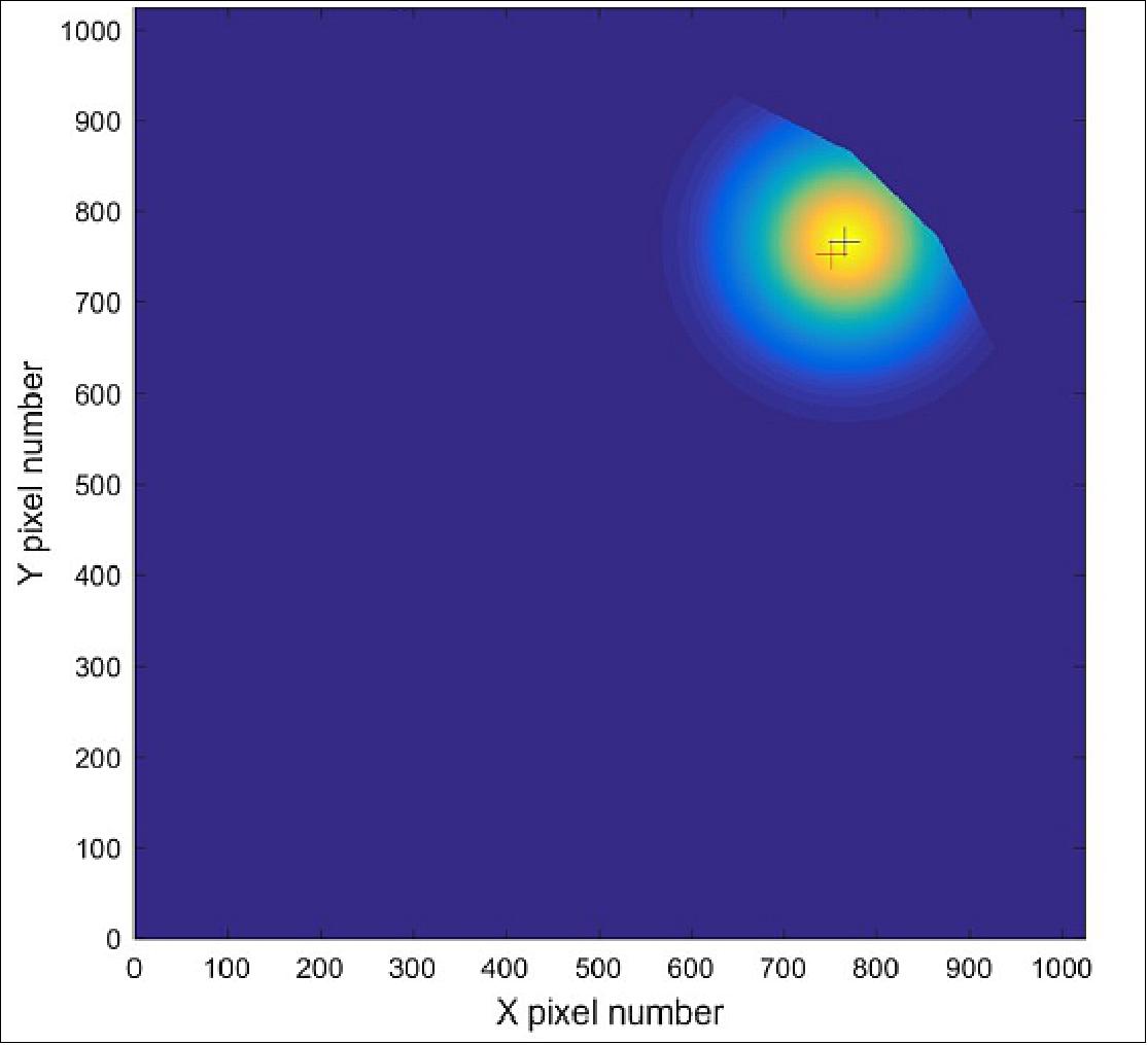
Cropping of Return Beam: When the beam returns from the CCRR to the OHU, depending on how much the CCRR has translated, the beam can be cropped by the OHU aperture. Part of the beam does not pass through the OHU, meaning the power on the two detectors within FLLS decreases. The cropping doesn’t significantly affect the longitudinal system, since it uses only the phase of the returning signal to calculate displacement. However, cropping does affect the lateral system.
The lateral system uses a “center-of-mass” method to determine the centroid position. When the beam is cropped the calculated center-of-mass position differs from the real position. Figure 18 demonstrates the effect of cropping using a modelled Gaussian beam similar to that in FLLS. The blue cross shows the center-of-mass of the uncropped beam, while the red cross shows the centroid as calculated by the center-of-mass algorithm.
To compensate for this, it is assumed that the effect of cropping has angular symmetry around the center of the image, with the error in the calculated centroid always being toward the center. It is expected that there is a one-to-one mapping between the measured centroid position and the true centroid position. This mapping will be established as part of the calibration procedure and used to correct the measured centroid position.
Calibration of FLLS
Calibration is the process of correcting systematic errors in the measurements made by the instrument. In the case of FLLS, measurements are taken at different longitudinal and lateral displacements of the CCRR, and verified against an independent laser tracker system.
Since the lateral and longitudinal systems operate independently, they will be calibrated in two independent procedures. However, an additional range-dependent correction to the lateral system is needed, due to static optical imperfections, which will be calibrated separately. During testing the longitudinal system will be tested at different lateral offsets and the lateral system at different longitudinal ranges.
Error Sources in FLLS Measurements: The known errors within FLLS have been estimated, using preliminary analysis and breadboard testing. These contributors will either be removed during calibration as a known amount (or “offset”), or will be accounted for in the error budget of the instrument. ESA requires that the lateral system and longitudinal system both have an error of 300 µm or less.
An example of one of the known contributors for the lateral system is deviation in the returning beam angle from the CCRR. When the beam enters the CCRR, having travelled between 25 m and 250 m, it will be reflected in the direction in which it entered. However, thermal variations inside the CCRR may cause the petals comprising the CCRR to flex/distort slightly. This will vary the dihedral error (the angle between the petals), causing the returning beam angle to vary, and changing the position, and potentially the size, of the beam on the sensor. To account for this, the CCRR will be thermally controlled to ±1°C. Preliminary testing has shown that the dihedral error only varies by 0.05 arcsec over this range. By charting the variation of this angle over the thermally controlled range, a look-up table of beam movement per temperature value can be created. Thermistors on the CCRR will report the temperature of the CCRR in-flight. Using this value, the associated displacement error for that temperature will be read by FLLS software from the look-up table, and subtracted from the displacement measurement.
This error contributor also affects the longitudinal system. Whilst a different system, variation in the position of the petals of the CCRR will increase/decrease the path the beam has travelled. This will be measured by the longitudinal system and reported, falsely, as displacement. Again, prior knowledge of the expected deviation per temperature means the erroneous extra displacement measurement can be subtracted from the longitudinal displacement value.
An example of a contributor of the longitudinal system that is independent of the lateral system is the clock reference accuracy. The clock sets the frequency of the amplitude-modulated signal carried by the laser. The accuracy of the clock is a fixed value – 100 parts per billion – which in turn affects the accuracy to which the displacement measurement is known. The effect it has scales with distance. However, because the accuracy is constant, it can be accounted for in the displacement measurement.
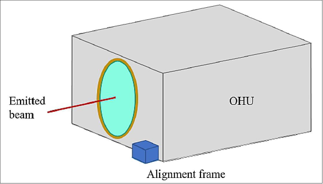
Reference Frames: Calibration also ensures the measurements made by FLLS are in the correct reference frame. FLLS has several different reference frames, relating to its subsystems. Measurements are made in the OHU boresight frame (aligned with the path of the outgoing laser beam), but are transformed into measurements in the alignment frame of FLLS, defined by a feature mounted to the side of FLLS (Figure 19). This is to enable FLLS to report displacement with respect to the spacecraft, once mounted to the spacecraft bus.
Calibration Setup: The calibration of FLLS will take place at SSC ( Surrey Space Centre), at the University of Surrey, who are collaborating with Neptec UK on this project. SSC have several laboratories and cleanrooms available for space hardware integration and testing. Calibration of FLLS will take place on an optical bench within one of the laser-safe laboratories. A diagram of the calibration setup is shown in Figure 20.
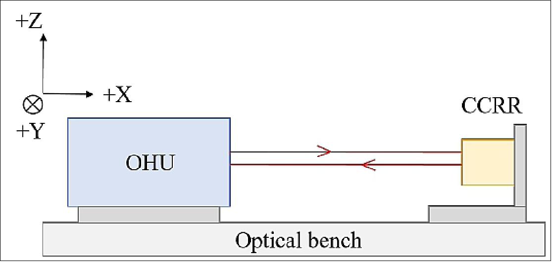
Calibration Setup of Longitudinal System: The displacement of the CCRR is measured by the phase difference in three modulation frequencies of 500 MHz, 100 MHz, and 0.5 MHz. The modulation cycles between these three frequencies, with each one responsible for an interval of ranges determined by the corresponding wavelengths. The phase is calculated by the LCEU and read out as a displacement, which is corroborated by an independent laser tracker instrument.
The CCRR will be translated by 15 m from a starting position of 1 m from the OHU window. The CCRR will be translated by intervals of 0.5 m in the 15 m range, in the +X direction and then back again along the same path in the -X direction. This ensures there is no discrepancy between positive and negative movement in the longitudinal system. It will also test the ability of FLLS to continue measuring displacement as the CCRR moves between two range ambiguity distances. Every movement of the CCRR will also be measured by the laser tracker. This will create a set of FLLS displacement values and laser tracker displacement values.
Longitudinal Calibration Model: The displacement measurements from FLLS and the laser tracker will be compared over the measurement range mentioned in ”Calibration Setup of Longitudinal System”. This will highlight any discrepancies between the two data sets. The longitudinal calibration model will be the mapping between these two sets of data, providing a correction to the FLLS data if required. If there is an additive offset between the two data sets this can be calibrated out simply by subtraction. This type of offset will likely be caused by path length differences expected from the contributors in the longitudinal system error budget analysis. The summed value from these contributors will act as a constant to be subtracted from the displacement data.
Calibration Setup of Lateral System: The OHU detector images the returning laser beam after it has passed through the OHU optics. The lateral calibration is a multi-step process that maps the calculated centroid of the imaged beam, in detector coordinates, to the position of the CCRR, in the OHU’s spatial coordinate system. The OHU coordinate system is defined by the alignment cube mounted on the side of the OHU, as discussed in ”Reference Frames”.
Calibration of the lateral system is performed in three steps: setup of the system, collection of measurement data, and creation of the calibration model. First, the OHU coordinate system is defined by the position of its alignment cube, and the laser tracker is configured to use this coordinate system. The resulting position measurements of the CCRR – by the laser tracker – provide a set of “truth data” for the subsequent calibration procedures. The truth data are used as a reference point against which to verify the lateral position as reported by FLLS.
Once the coordinate systems have been established, a grid of CCRR positions is constructed to cover the field of view of FLLS, and measurements are taken at each point by both FLLS and the laser tracker. The CCRR will be translated using a set of high-accuracy translation stages. The calibration consists in the mapping from the detector output at a given CCRR position to the corresponding position measurement from the laser tracker (the truth data). From these discrete measurements, a continuous mapping is generated by interpolating between grid points with a multivariate spline function. This data set is used to create the lateral calibration model.
Lateral Calibration Model: A separate calibration model is required for the lateral system, due to the different method of measuring displacement. The calibration process establishes a mathematical model that describes the relationship between the position of the CCRR and the position of the return beam on the sensor. The model accounts for possible optical distortion and a translation or scaling factor.
As discussed in ”Cropping of Return Beam”, a “center of mass” algorithm determines where the center of the beam on the lateral detector is. Pixels below a threshold intensity are disregarded. A quasi-circular mask is applied to the detector image to simulate a circularly symmetric FOV. This enables the system to compensate for cropping at the edges of the FOV. The shape of the measured beam is compared to a reference Gaussian profile, to determine the quality of the laser beam, and monitor potential degradation of the beam shape over the mission lifetime.
Performance Testing of FLLS
Testing of the FLLS system is split into short-range (< 7 m), mid-range (7 – 70 m), and long-range (70 – 250 m). Testing at different ranges ensures the two systems within FLLS give accurate measurements across the full displacement range. At each of these longitudinal distances the CCRR will be moved by its full lateral range, ±25 mm in Z and Y axes. A laser tracker system will be used to monitor the position and movement of the CCRR.
Short-range Testing: Testing FLLS at short-range will be achieved at the University of Surrey on an optical bench in an optical laboratory. This test will measure a maximum longitudinal displacement of 6 m (TBC). The CCRR will be displaced in the +X direction at 0.2 m (TBC) intervals up to the full 6 m distance and back to the original position. A laser tracker system will continuously monitor the position of the CCRR and verify each measurement reading.
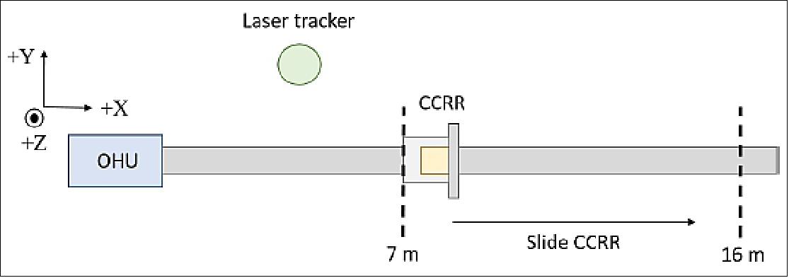
Mid-range Testing: A sliding 16-m-long test will also be carried out, to test the ability of FLLS to measure displacement continuously. The test will start at 7 m, moving the CCRR to 16 m, and back to 7 m. This test is preliminarily planned to be carried out at RAL Space, in Harwell, UK. A 16-m test will show how measurements made by FLLS transition between two of the three modulation frequency ranges (Calibration Setup of Longitudinal System). The movement of the CCRR is independently verified by a laser tracker system.
Currently, the maximum range planned to test at is 70 m. This will also be carried out at RAL Space. This static test would position the OHU on one side of the 70-m-long space, and the CCRR on the other side. The CCRR would move laterally by the full amount, and longitudinally by less than 1 m, at 70 m.
Long-range Testing: Since there are very few 250 m indoor test facilities, it is currently not planned for FLLS to be tested at the full range. Instead, FLLS will be tested at several intermediate distances, to verify the performance over those ranges, and the accuracy extrapolated to 250 m.
The extrapolation method will use least squares regression from the measured accuracy (the dependent variable) and the measured range (the independent variable) on the function in Equation 1 to calculate the extrapolated accuracy, A:

where R is the range in µm, BRI are the range-independent biases in µm, BRD are the range-dependent biases (dimensionless), NRI are the range-independent noises in µm, and NRD are the range-dependent noises (dimensionless).
Preliminary plans are being made to test FLLS at 140 m, using a multi-pass system of mirrors within the RAL Space facility. The design for this test, and the value of potential contributing errors, is currently under analysis.
Future Applications
The scope for applications of the completed FLLS (Fine Lateral and Longitudinal Sensor) is wide. The high accuracy with which FLLS can measure displacement makes it suitable for a wide variety of missions.
One of the most immediate uses of FLLS is in position-monitoring, as in PROBA-3. The advent of satellite constellations means more precise measurements of the position of each craft within the group will be required.
Constellations of satellites have also been proposed to create large-scale observatories, where FLLS has two separate applications. The first is, again, in monitoring the relative positions between craft in the constellation. The second is regarding the deployment of large-scale structures in space. FLLS would monitor the structural distortion before, during, and after deployment, and provide in-flight compensation to the instrument’s operation; for example, correcting the data that it collects. One example of such a large-scale mission is the Athena X-ray observatory. 27)
FLLS could also be used to monitor the position of telecommunication antennas. Precise positioning on the ground requires accurate knowledge of antenna pointing in space. FLLS could be set up on the telecommunication satellite to monitor de-pointing and movement of the antennas whilst in orbit. Any measured movement can either simply be monitored and recorded, or passed back to the on-board computer to correct.
Further into the future, FLLS could be used on lunar or Martian missions. Deployable mechanisms used by future landers and sample return missions may need stability or deployment monitoring. Once permanent structures are built on the lunar surface, these also may require accurate positioning. FLLS can measure three axes of movement, making it the ideal tool for many space-based applications.
In summary, FLLS is a high-accuracy, displacement-measuring sensor, to be used in the PROBA-3 mission to monitor satellite displacement. It will be the first formation-flying technology with such high accuracy– 300 µm – and will pave the way for future precision formation-flying missions.
The calibration of FLLS will be carried out separately on the two independent systems: the lateral system and the longitudinal system. The lateral calibration will align movement of the CCRR to the FLLS alignment frame, and establish a mapping from beam centroid movement on the lateral sensor to displacement of the CCRR. The longitudinal calibration will determine the fixed offset in distance measurements. The calibration will take place at SSC.
The performance of FLLS will be tested at static distances of 7 m and 70 m, and at varying distances between 7 m and 16 m, with scope for a static test at 140 m. The performance of FLLS at distances beyond this will be extrapolated from shorter-range test data. The tests will take place at RAL Space, in Harwell, UK.
Suitable for any type of mission requiring accurate displacement measurements, FLLS is adaptable. Examples of applications include monitoring displacement between satellites in constellation, measuring structural distortion before, during, and after deployment of large-scale structures, and fine-tuning positioning of telecommunication satellite antennas.
The spacecraft combine standard platform technology with new technology for formation flying, command, GNC (Guidance, Navigation & Control), relative metrology sensors and thrusters.
ISL (Intersatellite Link)
The ISL capability is used to exchange data between the different elements of the constellation or network spacecrafts, either for time, attitude and position synchronization, for relative position determination or even for telemetry relay to Ground. Since ISLs are used in a very specific context, their requirements are fairly different from those of traditional telemetry, tracking and command subsystems, which are more directed to ground-satellite communications. ISLs are used to exchange critical data and therefore require lower latencies and transmission error rates and usually operate without any ground intervention. For this reason, the Space market demands a new enabling generation of communication solutions that can cope with these requirements. 28)
GAMALINK is a multifunctional SDR (Software Defined Radio) communications and networking platform, born in the terrestrial domain, spun into space for the small satellite market and now upgraded to meet the specific requirements of ISLs. One of its applications is the PROBA-3 mission of ESA, whose goal is to demonstrate in-orbit the concept of formation flying using 2 satellites and to study the Sun corona. The critical ISL subsystem will provide time correlation and synchronization between the two satellites, enable the exchange of formation control data among the platforms and determine their relative distance during the complete orbit including the precise formation flying maneuvers. Apart from the challenging performance requirements, the ISL must also be able to survive the harsh radiation environment.
ISLs have different challenges to tackle than those of TT&C subsystems, which shows a real need for this application that cannot be satisfied with the current existing solutions in the market.
Link availability: One of the major differences that ISLs have from regular TT&C systems is the availability requirement. In traditional mission configurations, space assets communicate with one (or several) ground stations in pre-established visibility periods. This means that all communications from or to space, as well as all actions taken during the mission, are planned in advance and accounted for in operations. In short, the ground link does not need to (and cannot) be always available.
ISLs, however, are designed for different mission concepts, involving multiple satellites and which are more dynamic in nature, requiring faster adaptation to the mission conditions. In such an environment, the different spacecraft need to be able to establish a link immediately when they need it, in order to guarantee continuity in coordination and safety of the formation. This means that there will be at least some parts of the mission where the ISL needs to be permanently available.
This challenge needs to be tackled at both system and subsystem level. Permanent availability requires the ISL to be always operating. This has a strong impact on the power budget of the satellite, since RF subsystems are inherently power demanding. It also requires that the antenna configuration is defined in order to ensure permanent coverage in any specific mission conditions (usually omnidirectional coverage is required). Hence, the ISL needs to be able to manage the antenna selection autonomously and seamlessly, which is challenging from a design point of view.
Latency: In the same line, latency is also currently handled in different terms than traditional TT&C systems. Indeed, given the predefined visibility periods with ground stations, data is transmitted with high latency, both on uplink and downlink. The command uplinks are meant to be executed as part of the overall operations plan, at a defined time, and therefore can be uploaded in advance. As for downlink of telemetry, this information is processed offline and therefore does not have any kind of latency requirements.
Multi-satellite cooperative missions, however, need ISL data to be exchanged in realtime, in order to be able to coordinate actions and maneuvers between the platforms. For formation flying missions, latency is critical, in order to ensure that the different platforms know their relative position and attitude with adequate time accuracy. This adds a new challenge, mainly in terms of attitude control and guidance software development.
Reliability: In multi-satellite missions, ISLs are considered critical subsystems. In case of a failure, the platforms lose their ability to cooperate, either momentarily or permanently. This is no different from current space communications subsystems, since if the satellite cannot establish a link with the ground, no data can be sent from orbit and the mission is lost. However, in terms of data reliability, the criticality of TT&C systems is lower. If a message is deteriorated because the channel conditions are degraded, it can try later on a different ground station pass. Operation procedures account for these situations and the satellite is not lost.
In collaborative missions, such an event can jeopardize the satellites formation. If corrupted data are received, this may lead to a misinterpretation of a given satellite information, for instance, and to a bad decision from the other spacecraft. For this reason, in practice, ISLs need to be designed for lower BERs (Bit Error Rates) and considering efficient FEC (Forward Error Correction) techniques, which not only allow for message recovering, but also do not compromise the latency requirements.
Networking: The last three challenges are common to all space missions relying on ISLs. Platforms need to send a message immediately (high availability), with short delivery times (low latency) and ensuring that it is correctly interpreted at the destination (high reliability). The networking challenge is related with a capability that is highly desirable when the mission involves more than two satellites, such as scalable swarm missions or satellite networks. A network would simplify share data between all platforms.
GAMANET gathers satellites and ground stations in a transparent and integrated network, in order to maximize coverage and throughput of each space platform. This concept will be demonstrated in the upcoming QB50 mission, which will deploy a network of 50 CubeSats into orbit.
Such a network needs to be self-managed by the nodes creating it in order to ensure independency from ground intervention. It also needs to have a low overhead in communications or otherwise it will reduce the effective data rates and increase latency. These requirements are hard to achieve, which will ultimately increase the demand for more bandwidth and higher raw data rates in ISL communications.
Synchronization: Whether in a network or in a point-to-point ISL communication system, another major challenge is the synchronization. Coordination requires, not only that spacecraft are able to communicate effectively but also to perform their actions in a coherent fashion. In LEO missions, satellites can take advantage of GNSS systems to provide a reliable time reference, but in higher orbits they need other procedures to ensure that their working clocks are aligned.
Such a challenge is tightly connected to ranging, another useful capability in satellite constellations that allows the spacecraft to determine their relative distance. Accurate ranging techniques rely on propagation time measurements to calculate this distance. In order to determine the free-space time, other internal propagation times (software and hardware) need to be accurately known throughout the mission lifetime. Since electronic parts have variable delay times, depending on several factors, such as temperature, ageing or total dose radiation effects, this imposes a considerable design challenge in an ISL design.
PROBA-3 mission: The two PROBA-3 satellites will be injected into a highly elliptical Earth orbit, 600 km x 60,524 km, and perform the formation flying demonstration activities and scientific experiment near its apogee. In view of the specific PROBA-3 orbit, the satellites will cross Earth's radiation belts and its mission lifetime over 2 years, radiation-hardening techniques and SEE mitigation strategies must be present and implemented throughout the ISL design implying additional challenge. Finally, to complement and compare the results with the other on-board formation flying metrology systems, radio frequency ranging algorithms will be implemented in the ISL platform, providing an interesting alternative to determine the relative distance between the satellites.
GAMALINK Platform
GAMALINK is an advanced SDR (Software Defined Radio) communications platform for space vehicles developed by TEKEVER (Portugal), which provides simultaneous support for multiple types of ground and ISLs. By creating mobile wireless ad-hoc networks in space, GAMALINK provides unprecedented flexibility for satellite constellations and flight formation missions, enabling the creation of ISLs for synchronizing and coordinating actions. Additionally, GAMALINK receives and decodes GPS signals, providing precise positioning and timing information, it also supports precise ranging measurements. GAMALINK is available for different types of vehicles and missions, from nanosatellite missions, for which there is a CubeSat standard compatible version, to missions involving larger satellites and higher orbits.
The GAMALINK main specifications are listed in Table 5. It natively supports a frequency range going from UHF to S-band and is configurable according to mission and system communication and power consumption requirements.
Frequency range | 300 MHz to 3 GHZ |
Bandwidth | 40 MHz |
Data rate | up to 80 Mbit/s |
Positioning precision | 5 m (GPS) |
GPS update rate | 5 Hz |
PCB (Printed Circuit Board) size | 95.9 x 90.2 x 11 (mm) |
Total PCB mass | < 100 g |
Data interface | I2C, UART |
Storage capacity | from 2 x 2 GB |
Supply voltage | 3.3 V or 5 V |
Even though GAMALINK has slightly different challenges than those for the PROBA-3 mission, its purpose, technology and basic functionality are perfectly suitable for the mission requirements and needs. Therefore, GAMALINK was chosen as the baseline ISL subsystem for PROBA-3. However, some general design adaptations are needed in order to optimize the solution to the specific mission requirements. On the one hand some available features of the GAMALINK platform are not required and can be removed, saving therefore resources, on the other it brings new challenges that were not being considered so far, such as radiation-hardening and redundancy concerns. GAMALINK was originally developed for LEO missions with few months lifetime, without major design drivers in terms of implementing SEE mitigation techniques or design-level redundancy.
The approach to comply with the PROBA-3 requirements is to apply cold redundancy and use radiation-hardened qualified components. However, all components from the original design are not available in rad-hard nor high reliability grade for the desired functionality, in this case alternative solutions have to be considered.
Model Progress of Formation-Fliers
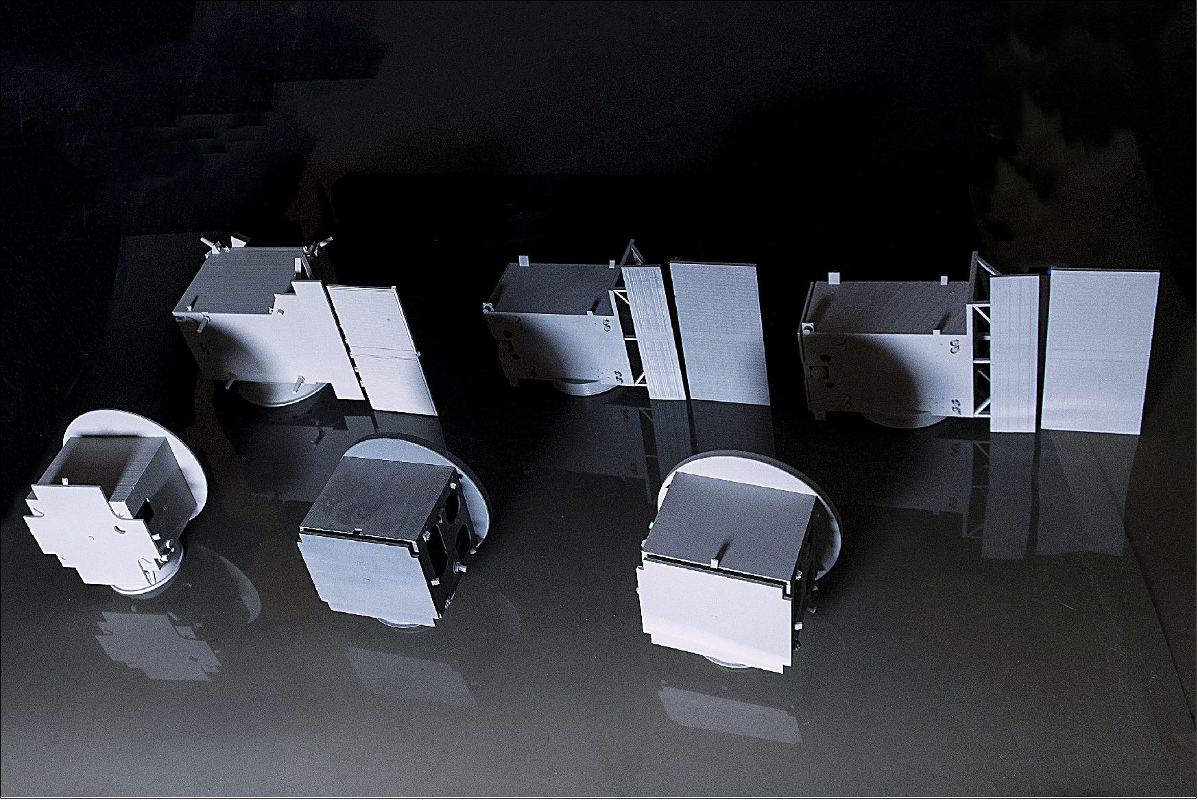
The design evolution of ESA's PROBA-3 double satellite mission is shown by this trio of 3D-printed models in Figure 24. “These paired models, 3D printed in plastic, were not made for show,” explains Agnes Mestreau-Garreau, ESA’s project manager. “Instead, they’re used almost daily. Because PROBA-3 will be the first precision formation-flying mission – with the two satellites flying in tandem– these models help the team to visualize their orientation, as well as to explain the mission easily to people. So the models have ended up somewhat battered as a result. 29)
“The first model set was printed after our System Requirements Review, followed by our PDR (Preliminary Design Review) and now MCM (Mission Consolidation Milestone) – with consequent changes in mission mass, volume and design details.“
The latest member of ESA’s experimental PROBA minisatellite family, PROBA-3’s paired satellites will maneuver relative to each other with millimeter and fraction-of-a-degree precision, intended to serve as the virtual equivalent of a giant structure in space and so open up a whole new way of running space missions.
As has become traditional with PROBA missions, the success of PROBA-3’s technology will be proven through acquiring high-quality scientific data. In this case, the smaller ‘occulter’ satellite will blot out the Sun’s fiery disc as viewed by the larger ‘coronagraph’ satellite, revealing mysterious regions of our parent star’s ghostly ‘corona’, or outer atmosphere.
When in Sun-observing mode, the two satellites will maintain formation exactly 150 m apart, lined up with the Sun so the occulter casts a shadow across the face of the coronagraph, blocking out solar glare to come closer to the Sun’s fiery surface than ever before, other than during frustratingly brief terrestrial solar eclipses.
The challenge is in keeping the satellites safely controlled and correctly positioned relative to each other. This will be accomplished using various new technologies, including bespoke formation-flying software, GPS information, intersatellite radio links, startrackers, and optical visual sensors and optical metrologies for close-up maneuvering.
PROBA-3’s next milestone will be the Payload Critical Design Review for its coronagraph, expected in the autumn followed by the System Critical Design Review for the mission.
Although the description of the PROBA-3 mission is still incomplete (regarding the spacecraft and its subsystems), the file is being presented on the eoPortal for reference. The mission will be updated as new information becomes available.
Development Status
• January 18, 2022: The PROBA-3 program, spearheaded by SENER Aeroespacial, the project's prime contractor for the European Space Agency (ESA), has accomplished several relevant milestones in the integration of the two satellites that will, for the first time, demonstrate a high-precision formation flight in space. 30)
- In the future, spacecraft formation flying technology will be used to replace bulky structures (such as telescopes) with small independent platforms, which are easier to launch into space and can be combined to form large assemblies that work as a single entity, while achieving equivalent performance.
- In parallel, PROBA-3 will perform scientific observations taking images of the Sun's corona by means of a coronagraph instrument, placed in one of the spacecraft. Formation flying technology entails placing one of the two satellites in front of the instrument's lens, thus blocking out the sun's disk and creating an artificial eclipse in flight.
- For SENER Aeroespacial, PROBA-3 marks a technical milestone, since it is the first time that a Spanish company has led the full development (i.e., is responsible for the entire flight and ground system) of a European Space Agency mission.
- The project has made an important step ahead with the start of the integration of the flight equipment, after the delivery of the platforms of the two satellites by Airbus Defence and Space. In this program, Airbus manufactures and integrates the platforms of both satellites. The first one, called Coronagraph Spacecraft (CSC), contains the main instrument (coronagraph), whereas the second satellite, called Occulter Spacecraft (OSC), carries an occulting disk that cover the sun's disk as seen from the other satellite. Airbus delivered the structure of both satellites already integrated with the propulsion system, harness and the thermal control system. This platform integration was carried out at the company's facilities in Madrid (Spain).
- The two satellites are now at the QinetiQ facility in Kruibeke (Belgium). For this program, QinetiQ is leading the activities to develop the avionics system, integrate all the electronic units within the platform, perform overall system verification and prepare the operations. The first flight equipment are already being installed on the OSC, and the integration of the CSC is expected to start early 2022, as this last unit was received in mid-December.
- At the same time, SENER Aeroespacial has completed the activities related to the design, manufacturing and testing of the high-stability Optical Bench Assembly (OBA) of the Coronagraph spacecraft. The bench has been assembled in SENER Aeroespacial facility in Bilbao (Spain). The last step has been the integration of the coronagraph instrument, the cornerstone of PROBA-3 scientific mission, developed by a consortium led by CSL (Centre Spatial de Liège). Such integration of the payload in the OBA has been realized by a joint team of CSL and SENER Aeroespacial employees, making use of the CSL facilities in Liege (Belgium). The bench and instrument are now at QinetiQ, ready to be integrated into the CSC.
• March 29, 2021: The longest corridor in ESA’s largest establishment was turned into a test site for one of the Agency’s most ambitious future missions, PROBA-3. The two satellites making up this mission will line up so that one casts a shadow onto the other, revealing inner regions of the Sun’s ghostly atmosphere. But such precision formation flying will only be possible through a vision-based sensor system allowing one satellite to lock onto the other. 31)
- The PROBA-3 pair will fly at a nominal 144 m apart for coronal observations, while in addition performing formation reconfiguration maneuvers that will change their distance all the way down to 25 m, and up to 250 m.
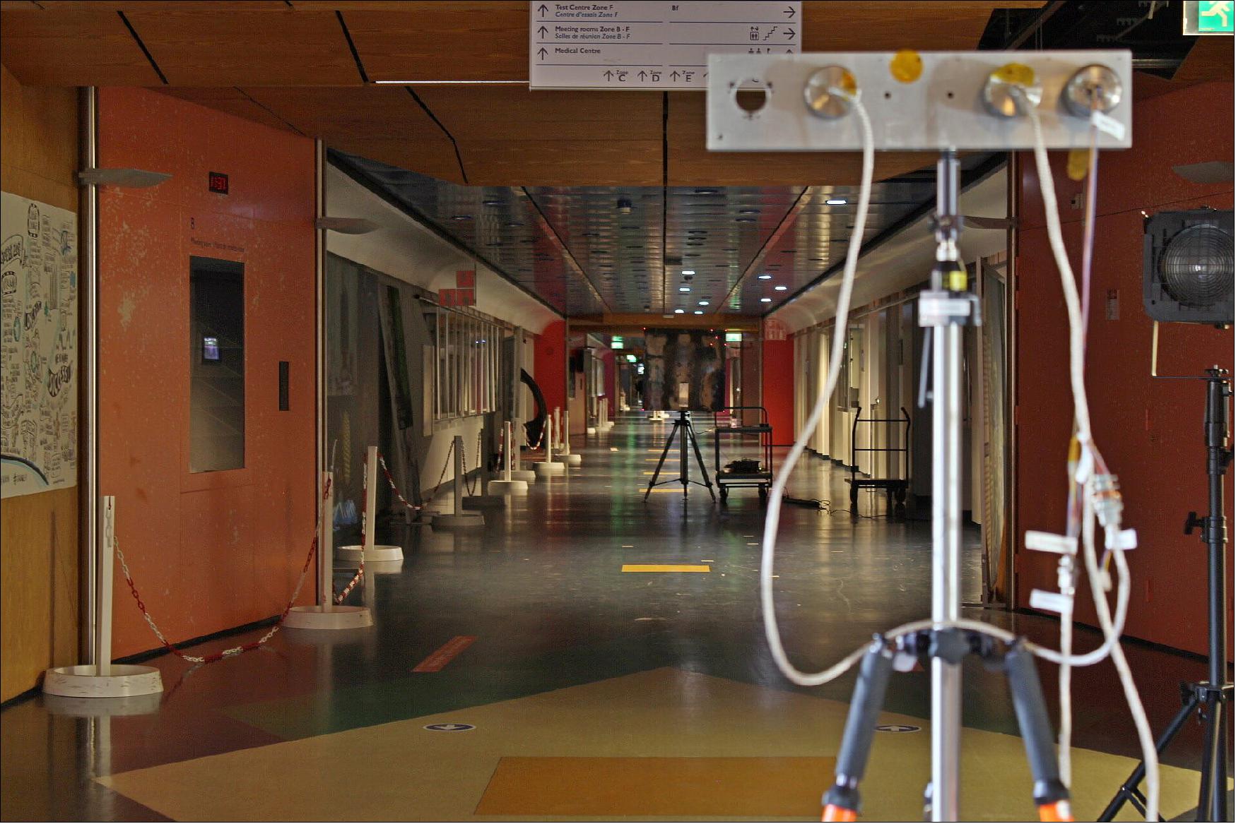
- Testing of this sensor system to make this possible took place at ESA’s ESTEC technical centre in Noordwijk, the Netherlands, using its 230-m-long main corridor, which links project offices with technical laboratories and the establishment’s satellite Test Centre.
- Lights were dimmed and exhibits removed to allow test-versions of the cameras to observe a flight-like target bearing LED displays down the entire length of the corridor.
- “This vision-based sensor system is the initial way that the two satellites acquire formation, and re-acquire it once per orbit,” explains Damien Galano, ESA’s PROBA-3 project manager.
- “It is designed to allow the pair to find each other and estimate their relative position down to a few millimeters’ precision, across distances of 20 to 250 m, allowing the spacecraft to autonomously maneuver into formation. So we needed a long space to test it, and an indoor space such as this is much more controllable than outdoors, where wind and other disturbances would interfere with the setup.”
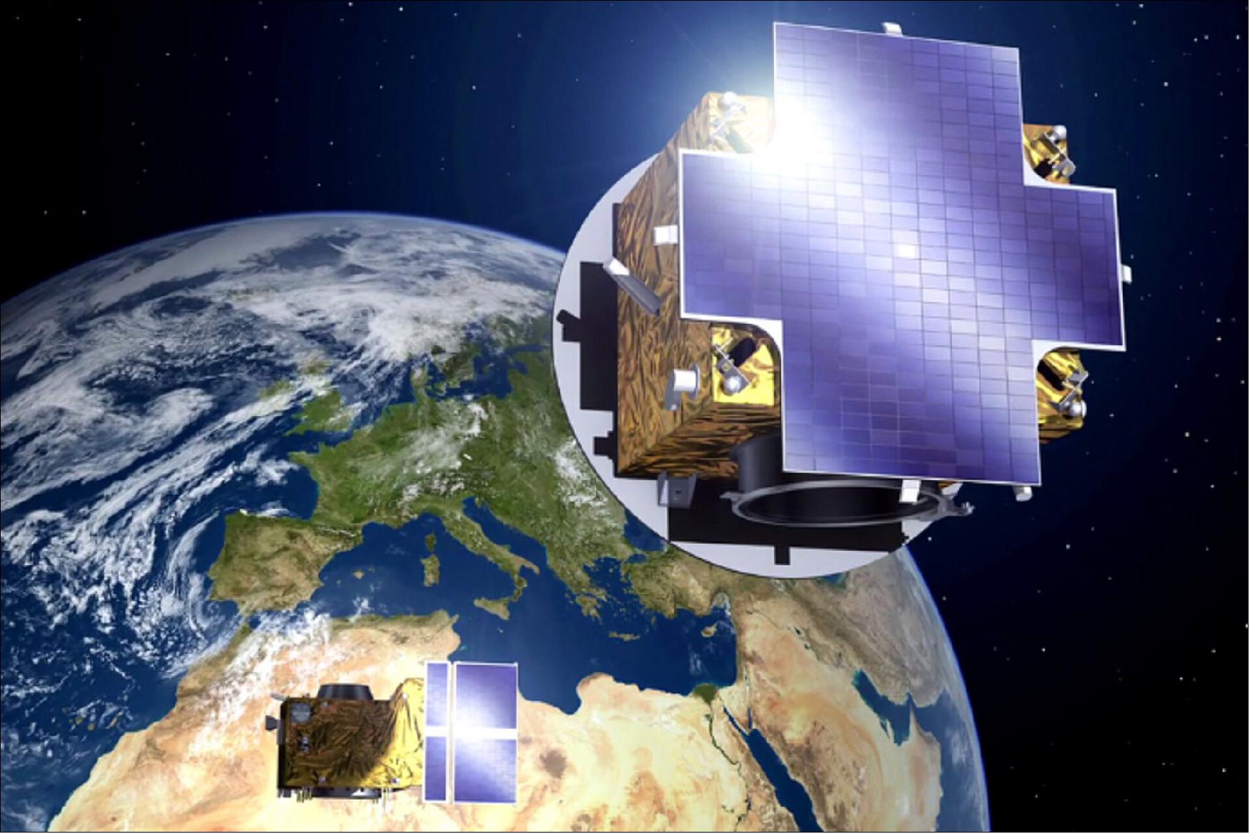
- PROBA-3’s two meter-scale satellites will line up in such a way that one – the ‘Occulter’ – blocks the blinding solar disk for the other ‘Coronagraph’. This will give researchers a sustained view of inner layers of its faint atmosphere, or ‘corona’, normally hidden in intense sunlight – except during brief solar eclipses.
- The two satellites will fly together in an elongated or highly elliptical 19.6-hour orbit,” says Raphael Rougeot, PROBA-3 mission system engineer.
- “Actively flying in formation throughout this orbit would be impractical. Instead the satellites only fly in formation for the six hours around the 60,000 km altitude top – or ‘apogee’ – of their orbit. The rest of the time they are maneuvered into a free flying relative trajectory which ensures the safety of the mission. Then, coming out of the bottom of their orbit – or ‘perigee’ – they must reacquire one another.”
- A set of cameras will be aboard the Occulter satellite, looking out for pulsing LEDs on the Coronagraph – one in each corner plus a smaller square pattern on the right hand side, intended to reveal the satellite orientation and enable proximity operations.
- Raphael adds: “Two cameras with different fields of view are needed. The first camera has a wide 15 degree field of view, used to find the Coronagraph. The second has a narrower field of view to provide the necessary millimeter-scale accuracy. Another sensor allows the synchronizing of their image acquisitions with the LED pulses. Such precise synchronization – down to a matter of 10 millionths of a second – is necessary because the light from the LEDs might otherwise be lost in the Sun’s spurious reflection on the Coronagraph, or in the bright Earth in the background. In addition, the cameras will also have a filter optimized for the near-infrared LED light.”
- Testing of the camera system and a square meter LED-bearing target was spaced out at 30 m intervals along the length of the corridor, yielding promising results. In order to simulate solar stray light, a specific lamp with the correct spectral properties was used. This lamp was specially characterized by ESTEC’s Optics Laboratory for this test.
- As a follow-up, a smaller version of the LED target was mounted on a rail-mounted robotic arm in ESTEC’s GRALS (Guidance Navigation and Control Rendezvous, Approach and Landing Simulator). This 33-m long facility is used to simulate close approaches, rendezvous and docking between space objects.
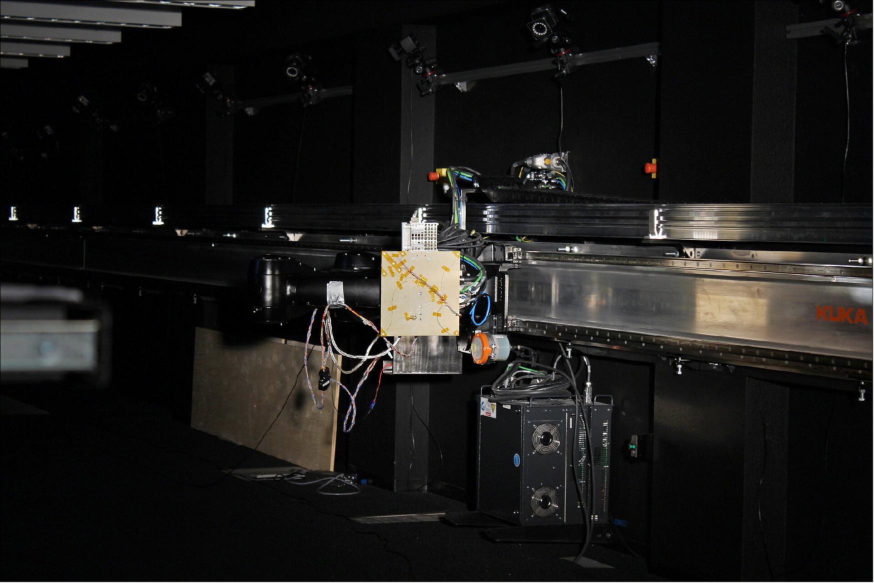
- Jonathan Grzymisch, PROBA-3 Guidance Navigation and Control system engineer, explains: “The robotic arm moved the LED target along a pre-programmed pattern as the cameras watched, allowing the instrument software to calculate its relative dynamic trajectory continuously. This allows us to characterize the sensor performance on a deterministic dynamic basis. Both tests performed well, thanks to the cooperation of ESTEC’s Facility Management and the relevant technical sections.”
- PROBA-3’s vision-based sensor system has been developed by the Technical University of Denmark (DTU). The team could not be present in person at ESTEC due to COVID-19 restrictions, but supported the testing remotely while ESA engineers prepared and ran the test.
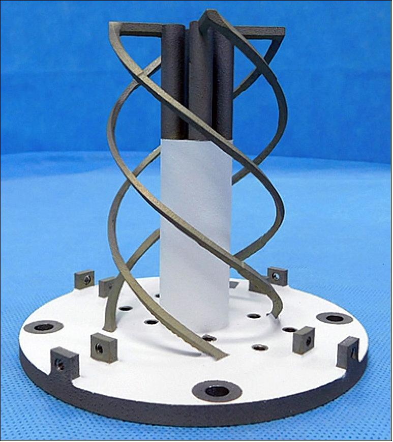
• October 9, 2019: SENER Aeroespacial and CATEC have completed the delivery of the telemetry and telecommand antennas for the European Space Agency's PROBA-3 mission, for which SENER Aeroespacial is the prime contractor of the entire mission. 32)
- This group of antennas includes the first one made by SENER Aeroespacial using metal 3D printing (additive manufacturing). This is one of the first space antennas in the world developed using this technology, and the first one made in Spain, which is a milestone for the Spanish space industry. It also reaffirms the vision of both institutions, SENER Aeroespacial and the research organization CATEC, that it is feasible to use this type of solution as an alternative to conventional manufacturing technology in those cases where the latter does not offer a viable solution.
- In recent years, SENER Aeroespacial has been providing and participating in several high- and medium-gain antenna pointing systems for the ESA's main science missions, such as BepiColombo, Solar Orbiter, Euclid and Juice. As part of developing these systems, SENER Aeroespacial designs, verifies and integrates key communications elements, most notably the antennas and the rotating joints integrated inside the mechanisms.
- Within this framework, SENER Aeroespacial and CATEC worked to develop a helical antenna that was printed with an aluminum alloy and subjected to demanding verification and qualification tests, which resulted in obtaining the flight acceptance for the European Space Agency's PROBA-3 mission.
- "SENER Aeroespacial came to us in 2016 with the challenge of developing a helical antenna for the European Space Agency, and with a real chance of flying. The functional requirements of this product take to the limits additive manufacturing due to the dimensional tolerances for producing such a complex geometry," notes Dr. Fernando Lasagni, Technical Director (Materials & Processes) at CATEC.
- "SENER Aeroespacial found the perfect partner and ally in CATEC to achieve the complicated goal of manufacturing and qualifying the first 3D-printed metal antenna, with all the advantages that entails, while maintaining both radio-frequency and thermo-mechanical performance. Both CATEC's previous experience and knowledge and the good communication between the work teams proved fruitful in developing procedures that not only allowed us to deliver the first 3D-printed antenna, but that laid the foundations for future collaborations in which this technology can add value to any SENER Aeroespacial product," says Esteban Celemín, Project Manager for the PROBA-3 antennas at SENER Aeroespacial.
- CATEC, along with Airbus, has already developed the titanium supports for the solar panels of a telecommunications satellite (a milestone in Europe due to the criticality of the components) and more than a hundred fittings, brackets, fairings and other applications for the aeronautical and space industry. Together with the company CITD, CATEC has also developed titanium and aluminum hoisting tooling for the CHEOPS satellite, and they are currently working on developing the secondary structure for the JUICE mission, as well as other hardware for the Ariane launcher. "The experience we have gained in other programs where we have developed flight components made of titanium alloys was essential for SENER Aeroespacial and the European Space Agency to trust in this team of engineers & researchers for this ambitious project" states Lasagni.
- "The work of CATEC consisted in supporting SENER Aeroespacial in the design of the antenna, integrating into it the manufacturing possibilities and constrains for the technology, defining the validation tests and developing the quality assurance process for manufacturing flight components, and at the same time complying with ESA's rigorous verification process," notes Carlos Galleguillos, Project Manager at CATEC.
- Moreover, "SENER Aeroespacial was responsible for the design, machining of the interfaces and conducting an intensive functional, thermal, radiofrequency and vibration testing program. All of the tests were completed successfully, which resulted in obtaining the flight permit for the antenna," explains Eduardo Lapeña, the thermo-mechanical engineer at SENER Aeroespacial who is responsible for these antennas on the PROBA-3.
• May 8, 2019: This patch antenna (Figure 31) under test at ESA’s technical heart is designed to maintain a radio link between the two satellites making up the Proba-3 mission, allowing the pair to fly in formation to maintain an artificial eclipse of the Sun. 33)
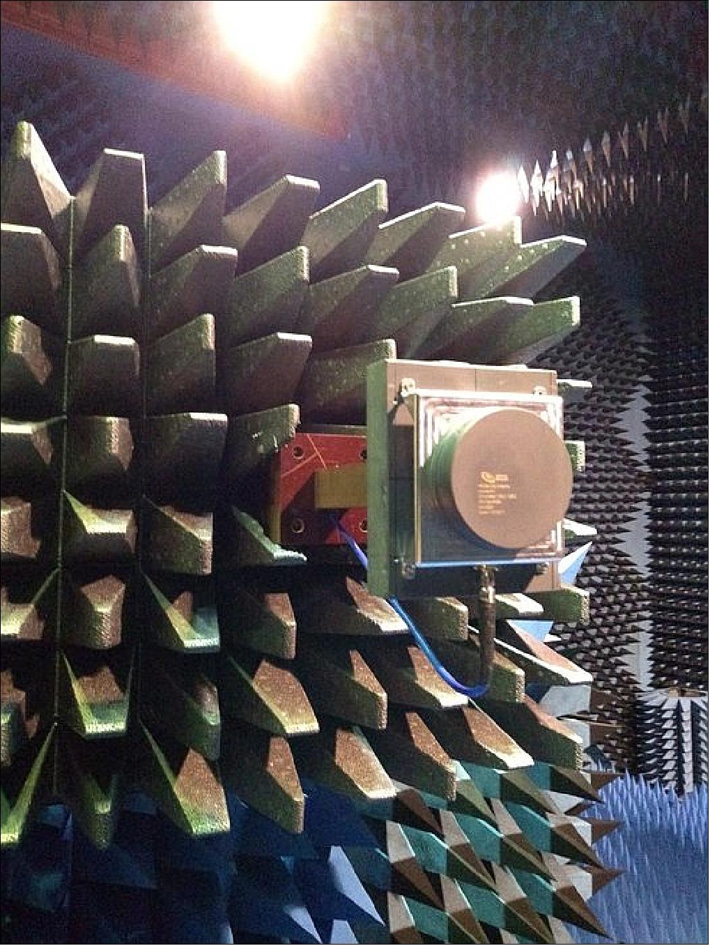
- Proba-3 is ESA’s – and the world’s – first precision formation flying mission. A pair of satellites will fly together maintaining a fixed configuration as a ‘large rigid structure’ in space to prove formation flying technologies.
- The mission will demonstrate formation flying in the context of a large-scale science experiment. The paired satellites will together form a 150-m long solar coronagraph to study the Sun’s faint corona closer to the solar rim than has ever before been achieved.
- Inter-satellite links will be maintained using this radio antenna, which was developed along with its associated electronics by Tekever in Portugal.
• October 2018: PROBA-3 is the ESA Formation Flying demonstration mission, which has just finished the design phase and it is now starting the manufacturing and verification phase D aiming at a launch before beginning of the next decade. 34)
- One of the core technologies to be widely demonstrated is the Formation Flying System (FFS), i.e. the software and the hardware (actuators, sensors and metrologies) which will permit to autonomously perform, with the required strict accuracy, the maneuvers necessary for accomplishing mission scientific and technology demonstration goals, guaranteeing at the same time the mission safety thanks to the implementation of a robust perigee pass strategy, collision avoidance and go to safe maneuvers.
• July 17, 2017: ESA’s Science Program has agreed to support the technology-demonstrating PROBA-3, a double-satellite formation-flying mission tasked with observing a region of the Sun normally hidden from view. 35)
- The two satellites making up PROBA-3 will fly at a precise separation to cast a shadow across space, blocking out the disc of the Sun to reveal details of its ghostly surrounding ‘corona’ – usually masked by dazzling sunlight.
- PROBA-3, like all the missions in the PROBA series, is first and foremost a technology demonstrator, exploring precision formation-flying techniques so that future multiple satellites flying together could perform equivalent tasks to a single giant spacecraft.
- But, following a longstanding PROBA tradition, the mission has also been given an ambitious scientific goal: returning scientifically useful data is a good way of proving the technology works as planned.
- PROBA-3 will offer solar scientists a window on the inner segment of the solar corona – a mysterious region because it is more than a million degrees hotter than the surface of the Sun it surrounds.
- Up until now, the best way to observe the corona has been during a solar eclipse, although stray light through Earth’s atmosphere is a limiting factor.
- As an alternative, space-flown ‘coronagraphs’ create artificial eclipses inside Sun-watching satellites such as SOHO and STEREO, but stray light still bends around their blocking discs, limiting access to the all-important inner corona.
- PROBA-3 will get around this by flying the disc of its coronagraph on a separate satellite, exactly 150 m apart, lined up with the Sun. This should open up a new view of dynamic regions extremely close to the solar surface, where the solar wind and the eruptions called ‘coronal mass ejections’ are born. Coronal mass ejections are primary sources of disturbed space weather at the Earth.
- PROBA-3 is funded through ESA’s Directorate of Technology, Engineering and Quality, but in June the Agency’s Science Program Committee endorsed the mission for additional backing through the Directorate of Science.
- “It was clear that it would be very beneficial to have this mission supported in the Science program,” explains Andrei Zhukov of the Royal Observatory of Belgium, serving as Principal Investigator for PROBA’s coronagraph.
- “There was widespread enthusiasm in the solar physics community. The Science Program Committee is advised in turn by its advisory committees composed of scientists from all around Europe, giving independent endorsements, and they recommended PROBA-3 be supported as a ‘mission of opportunity’.
- “In plain terms, the running of PROBA-3’s Science Operations Center, which will process and distribute scientific data to scientists across Europe, will be funded by the Science program. This center will be hosted here in Belgium, with contributions to the data processing pipeline made by Germany, Poland and Romania.
Launch
Orbit: The reference orbit is a HEO (Highly-elliptical Earth Orbit) with a perigee of 600 km, apogee of 60,530 km, an inclination of 59º, and an orbital period of 19 hr 38 minutes.
The high apogee has been chosen to minimize the propellant consumption of the formation flying maneuvers. The orbit has a period of 24 hours. Formation flying will take place over a 12 hours arc centered on apogee allowing a minimum of 6 hours/day of coronal observations. Formation will be broken over the remaining 12 hours as differential gravitational effects would induce too large cold gas consumption. Data transmission will take place during the perigee pass. In order to minimize radiation dose from the Van Allen Radiation Belts the operational orbit will be inclined by 59º (Ref. 11). 36) 37) 38)
Non-Keplerian formation flying for both, ASPIICS and other science demonstrations, takes place during the apogee pass where the gravity gradient is very small. The perigee pass will be free-flying, with the natural evolution of the relative motion under the local gravity gradient.
ESA developed a simulator at ESA/ESTEC, a testbed facility intended to be of service for all formation flying mission demonstrations. PROBA-3 is the first ESA mission to use this facility. The testbed was developed by Belgium’s Spacebel, also responsible for PROBA-3’s flight software. The project was backed through ESA’s GSTP (General Support Technology Program), which aims to mature prototypes into operational hardware. 39) 40) 41)
Perigee, apogee | 600 km, 60,530 km |
Semi-major axis | 36943 km |
Eccentricity | 0.8111 |
Inclination | 59º |
RAAN (Right Ascension of the Ascending Node) | 84º |
Argument of perigee | 188º |
Orbital period | 19 hr 38 minutes |
The ultimate coronagraph: artificial total eclipse created using two spacecraft in flight formation (Ref. 15).
• The formation flying is maintained over 6 hours in every 20-hour orbit: around a factor 100 improvement in the duration of uninterrupted observations in comparison with a total eclipse.
• A technological challenge: the distance between the spacecraft is about 150 m, and the accuracy of their positioning should be around a few mm!
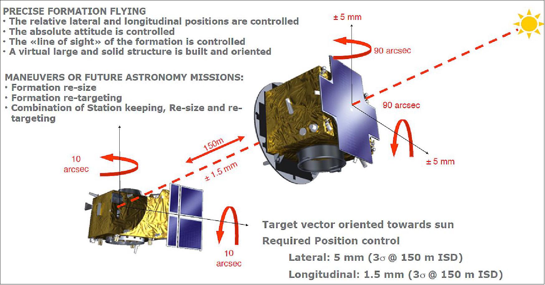
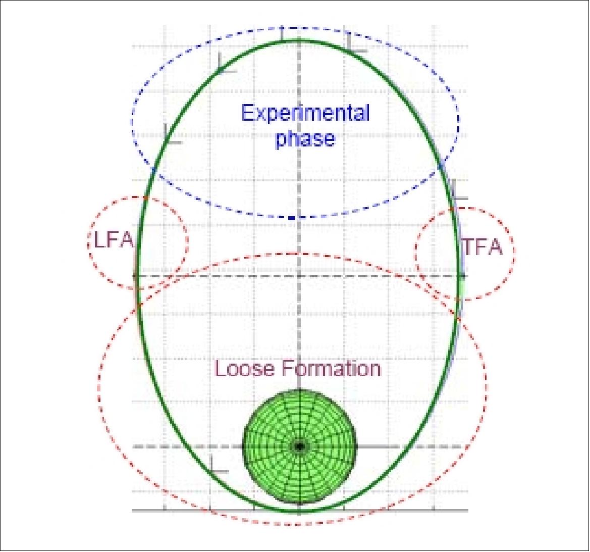
Mission
The two S/C will fly in formation acting as in a single rigid virtual structure during the apogee phase of the high elliptic orbit (Phases 3, 4, 5 and 6 in Figure 34). Depending on the orbit, according to ground command, the apogee activity can be “Coronagraphy” (i.e. highly precise station keeping for analysis of Sun corona images) or Formation Flying maneuver tests: Formation Resizing, Formation Retargeting, Formation Roll, Thruster Only Experiment, Rendezvous Experiment (RVX) or CAM Experiment. During the perigee phase (Phase 1 in Figure 34) the two S/C fly in free flight and Sun pointing, after having executed maneuvers for breaking the formation and guaranteeing a passively safe perigee passage (Phase 7 in Figure 34). Phases 2 and 8 are used to perform a roll flip and a roll flip back, needed to passively decrease the wheel momentum load in the CSC exploiting the Solar Radiation Pressure (SRP) on its asymmetric Solar Panel (Ref. 34).
FFS (Formation Flying System) Overview
One of the most critical and complex technologies for Proba-3 mission is the FFS (Formation Flying System), i.e. the Formation Flying Software (FFSW) and the HW (metrologies, sensors and actuators) permitting to carry out all the formation flying activities and operations. The FFS relies on the following HW:
• Metrologies:
- Fine Lateral and Longitudinal Sensor (FLLS), mounted on the OSC, to be pointed toward the corner cubes retro-reflectors (CCRR) mounted on the CSC
- Shadow Position Sensor (SPS), mounted on the CSC
- Visual Based Sensor (VBS), mounted on the OSC, to be pointed toward the mires mounted on the CSC
- Relative GPS (rGPS), FFSW function on-board the OSC computing the relative position and velocity during perigee pass based on GPS measurements
- Inter Satellite Link (ISL), for range measurement and transfer of data between the two S/C
• AOCS sensors:
- 3 Star trackers (STR) on each S/C
- Two 3-axes Inertial Rate Sensors
- Fine and Coarse Sun Acquisition Sensors (FSAS and CSAS)
- GPS
• Actuators:
- 12 10 mN Cold Gas Thrusters (CGT) on the OSC
- 8 1N Mono Propellant Thrusters (MPT) on the CSC
- 4 Reaction Wheels on each S/C
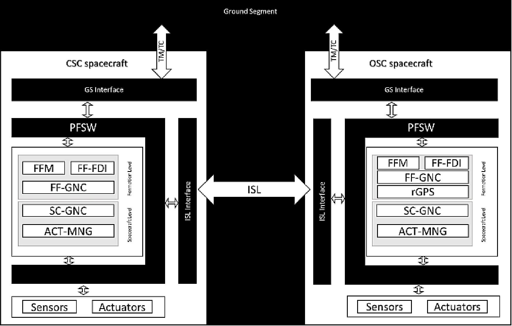
The following FFSW modules can be identified in Figure 35:
• Formation Flying Manager (FFM): This FFSW module plans, coordinates and manages the formation flying activities of the mission in an autonomous way. It allows a manual control of the formation from PFSW through low level commands. It receives high level commands from ground and it translates them into a formation timeline and mode. It derives the commands and actions for the FF-GNC and SC-GNC as result of the timeline scheduling, including FF-GNC and SC-GNC configuration and mode transition. It also monitors the correct execution of the plan corresponding to FFM mode.
• Formation Flying FDI (FF-FDI): This FFSW module coordinates the detection and flag processing coming from the different elements of the FFSW and provides alarms/warnings (to be processed and confirmed by system FDIR) detected at FFS level which could not have been solved by L0 recovery actions at FFSW level (collision risk detection, detection of possible FFS equipment failures, etc.).
• Formation Flying GNC (FF-GNC): This FFSW module controls the relative state (position and attitude) of the formation. The FF-GNC processes the measurements obtained from metrologies and from SC-GNC (directly or via the Inter-Satellite Link) for the determination of the relative position and attitude, and it executes the control actions required for acquiring the trajectories and attitudes computed by the guidance under the requests of the FFM, either commanding the Formation Flying Control (to control the OSC during formation flying operations) or the SC-GNC (to control the two S/C outside from formation flying operations). Three main elements are considered:
- Formation Flying Navigation (FF-N): This function of the FF-GNC module provides the best estimate of the relative position, velocity and attitude of the spacecraft. It is commanded by the FFM and it receives data from the metrologies both in the local spacecraft and in the other spacecraft (via the ISL) and from the SC-GNC and ACT-MNG. It also performs metrologies measurements pre-processing, synchronization and propagation. It provides the navigation solution with the required frequency to other FF modules. Relative navigation is based on a Kalman filter implementing the Yamanaka-Ankersen formulation (relative orbital propagation model for relative PV estimation) expressed in the Local Vertical Local Horizontal (LVLH) reference frame. Information coming from the rGPS, VBS, SPS, FLLS and ISL range is used when available (in other case relative state is computed based on relative propagation including solar radiation pressure model), together with absolute position and attitude information coming from SC-GNC. Additionally it performs: collision risk detection (through propagation), metrology data validity assessment (by checking input values against expected values and independent sources), self-assessment of estimated position and velocity covariance and state estimation validity, navigation using alternative metrology (VBS and SPS sensors), relative attitude computation, ancillary absolute orbit processing (prediction of events, counting number of orbits). In the OSC it includes the functions for propagating FLLS measurements at 4 Hz using SC-GNC attitude estimation, to permit a more precise formation flying control (which expects inputs at 4 Hz) based directly on FLLS measurements.
- Formation Flying Guidance (FF-G): This function of the FF-GNC module receives the commands from the FFM, computes the reference state, position, velocity and attitude; and feed forward action in case of forced continuous phases (formation acquisition, coronagraphy, formation flying maneuvers), and calculates the orbital maneuvers and application times and direction in case of impulsive maneuvers (perigee pass DTMs, CGC, Go to Safe, CAM). In the calculation of the reference trajectories, formation safety is considered as the main driver, with minimization of ΔV as a second objective. A linear propagator using the Yamanaka-Ankersen formulation in LVLH and including solar radiation pressure model is implemented.
- Formation Flying Control (FF-C): This function of the FF-GNC module receives the relative position and velocity from the FF-N function, the inertial attitude estimation from the SC-GNC navigation, the FLLS measurements (interpolated by FF-N at 4 Hz) and the reference position and attitude from the FF-G function. It is a controller fully independent from SC-GNC control, and computes the forces and torques that are necessary for OSC spacecraft to keep the FLLS tracked and to follow the reference state for formation acquisition, maintenance and formation flying maneuvers (retarget, resize, roll, 6 DOF control with thrusters). It generates the commanding actions to be transmitted to OSC ACT-MNG module. The FFC is designed as a robust structured 6DoF controller using H-infinity and mu-tools. It is designed for a plant model based on the relative dynamics of the SC formulated in LVLH.
• Spacecraft GNC (SC-GNC): This FFSW module controls the absolute attitude of the spacecraft and estimates its absolute position. The SC-GNC processes the measurements from the absolute sensors for the determination of the absolute position and attitude and passes this information to the FF-GNC module to manage formation maneuvers. The SC-GNC runs on each spacecraft and similarly to FF-GNC is composed of the following main elements:
- S/C Navigation (GNC-NAV). The Navigation function in the SC-GNC computes the absolute position, velocity and attitude of the spacecraft from sensors data and performs Angular Momentum Management (AMM) monitoring. It also performs sensor measurements preprocessing, synchronization and propagation and provides information to the FF-GNC.
- S/C Guidance (GNC-GDC). The Guidance function in the SC-GNC computes the attitude profiles to be followed by the spacecraft.
- S/C Control (GNC-CTL). The Control function in the SC-GNC processes navigation estimates and guidance attitude profiles to generate the commanded torques needed to follow the reference profiles. It also computes AMM (Angular Momentum Management) commands to desaturate the wheels.
- Actuator Manager (ACT-MNG): This FFS module distributes the actuations computed by the SC-GNC/FF-GNC (force and torque) to each single thruster and reaction wheels mounted in the spacecraft depending on their configuration.
• Relative GPS (rGPS): This FFSW module computes the relative position and velocity based on GPS measurements. The reference frame used is WGS84 Earth centered fixed frame. The relative position and velocity (PV) refer to the relative PV of the center of phase of the antennas used by the GPS receiver on OSC and CSC. The rGPS function is commanded by the FFM and it receives data from the GPS receiver both in the local spacecraft and in the other spacecraft (via the ISL) and from FF-N for initialization purposes. In order to minimize delays in the navigation loop, the rGPS is located in the master satellite, i.e. the OSC.
PROBA-3 mission timeline: The PROBA-3 nominal mission lifetime is two years. The mission is composed by three main phases:
• LEOP (Launch and Early Orbit Phase), lasting less than 2 days
• Commissioning, lasting about 2 months
• Nominal Operations, lasting about 22 months.
It will be possible to extend the operations up to the maximum mission duration of about 2.5 years depending on the launch date. At the end of the operation phase PROBA-3 is decommissioned waiting for its passive reentry into the atmosphere. — Within the PROBA-3 nominal operations, the operation priority is addressed according to the objective importance: FF demonstration first, then science and finally experiments (Ref. 13).
FF (Formation Flying) Demonstration
The completion of the FF mission objectives depends on the execution of the FF demonstration tasks. The demonstration will start with small scale (few meters) rigid resize and retarget tests. The objective of these tests is to assess the initial accuracy of the uncalibrated system. Then calibration maneuvers will be executed. Dedicated maneuvers will allow metrology and GNC equipments performance characterization. Prior to the execution of full scale formation maneuvers, collision avoidance maneuvers will be demonstrated. Formation resize (from 25 to 250 m) and retarget (from -30º to +30º) will be finally demonstrated. This will include station keeping operations at different ISDs. The rigid maneuver objective is to demonstrate operations foreseen from future formation flying missions. In particular space telescope or interferometer mission will perform part of their scientific observation during rigid maneuver. Rigid maneuvers will require well defined trajectory, the highest accuracy metrology system and formation control with maximum level of performances. Loose maneuver objective is intended to demonstrate service operation and in particular move from point A to point B in order to perform an additional operation (e.g. station keeping or start a resize or retargeting maneuver).
Coronagraph Science
A total of 167 orbits are needed in order to complete the planed minimum 1,000 hours of coronagraph observations. The science payload on PROBA-3 consists of a distributed coronagraph system. The coronagraph system is composed by a Coronagraph Instrument and four SPS (Shadow Position Sensors) mounted on the CSC, and an Occulting Disk and six OPS (Occulter Position Sensors) mounted on the OSC. The coronagraph instrument will take images of the inner solar corona with observational parameters never achieved before. Broad and narrow band images as well as polarization measurements will be possible. The PROBA-3 spacecraft will fly during the apogee phase in station keeping configuration at about 150 m inter satellite distance. Coronagraph science operations will last about 4.5 months. The planning of these operations mainly depends on the availability of the dedicated downlink ground antenna (Ref. 13).
Experiments
Three experiments are currently considered within the PROBA-3 mission. Additional experiments may be included in the mission at the beginning of phase C. The experiments include:
• 6DOF (6 Degree of Freedom) control with thrusters
• Rendezvous experiment and Realistic Collision Avoidance (see P3RVX description below)
• FDIR (Failure Detection, Isolation and Recovery) test maneuvers (see FDIR description below).
A future interferometer mission will avoid the use of ball bearing reaction wheels to limit the internal vibration. Within the 6DOF control with thrusters experiment, PROBA-3 will repeat the formation maneuvers controlling the relative spacecraft position and attitude only with the thrusters.
In order to ensure spacecraft and formation safety in case of contingency, a distributed FDIR (Failure Detection, Isolation and Recovery) system is designed. PROBA-3 FDIR deals with the complexity of fault management of two spacecrafts flying in close formation. The FDIR system has to monitor and recover failures at spacecraft level (as a stand-alone entity) and failures that can cause a collision between spacecrafts. Any failure at spacecraft level could impact in the formation flying and vice-versa. PROBA-3 FDIR design is composed by two separated entities working together in the system: Spacecraft FDIR (SC-FDIR) and Formation Flying FDIR (FF-FDIR).
Distributed System Autonomy: The FDIR main principle is that lowest-level isolation and recovery is attempted first. This approach minimizes the impact in the system operation. Five recovery levels:
• L0: Action None (Unit Level Local recovery)
• L1:Unit/Function Recovery (Recovery by FDIR)
• L2: Unit/Function Reconfiguration (Unit substitution by FDIR)
• L3: OBC / System Recovery (Safe orbit entered & System Mode to MANUAL)
• L4: CAM (Drifting orbit entered & System Mode to MANUAL)
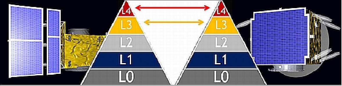
Sensor Complement
ASPIICS (Association of Spacecraft for Polarimetry and Imaging Investigation of the Corona of the Sun)
The Coronagraph on PROBA-3 is called ASPIICS and is developed by a consortium of European Institutes and Industries from Belgium, Czech Republic, Greece, Italy, Ireland, Poland and Romania. 42) The ASPIICS unprecedented field of view makes it uniquely suited for studies of the solar corona, as it will fill the crucial observational gap between the fields of view of Solar EUV imagers and conventional space coronagraphs (Figure 37). 43)
The top-level scientific objectives of ASPIICS are in first place to understand the physical processes that govern the quiescent solar corona by answering the following questions:
• Nature of the solar corona on different scales
• Processes that contribute to the heating of the corona and the role of waves
• Processes that contribute to the solar wind acceleration.
Secondly, to understand the physical processes that lead to CMEs and determine space weather by answering the following questions:
• Nature of the coronal structures that form the CME
• How do CMEs erupt and accelerate in the low corona
• The connection between CMEs and active processes close to the solar surface
• Where and how can a CME drive a shock in the low corona.
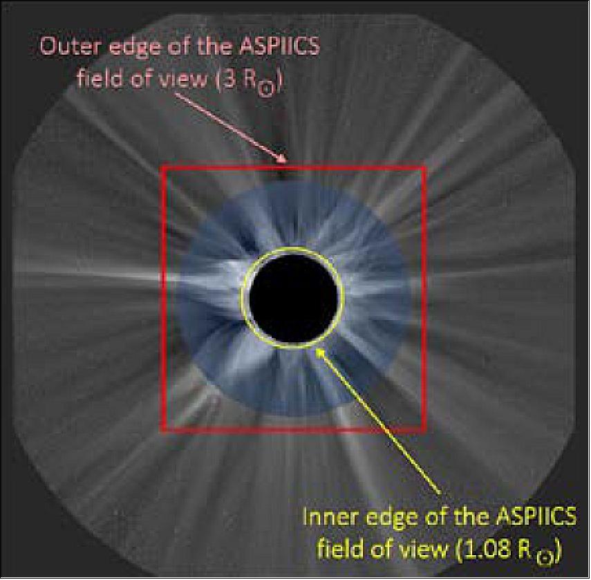
In the early 21st century, classical externally-occulted coronagraphs are limited in their performances by the distance between the external occulter and the front objective. The diffraction fringe from the occulter and the vignetted pupil which degrades the spatial resolution prevent useful observations of the white light corona inside typically 2-2.5 solar radii (Rsun). Formation flying offers an elegant solution to these limitations and allows conceiving giant, externally-occulted coronagraphs using a two-component space system with the external occulter on one spacecraft and the optical instrument on the other spacecraft at a distance of ~100 m. Such an instrument, namely ASPIICS, has been selected in 2010 by ESA to fly on its PROBA-3 mission of formation flying demonstration. 44) 45) 46) 47) 48)
The classical design of an externally-occulted coronagraph is adapted to the formation flying configuration allowing the detection of the very inner corona as close as ~0.04 solar radii from the solar limb. By tuning the position of the occulter spacecraft, it may even be possible to reach the chromosphere and the upper part of the spicules.
The ASPIICS (Association of Spacecraft for Polarimetric and Imaging Investigation of the Corona of the Sun) instrumentation, proposed by the Laboratoire d'Astrophysique de Marseille (LAM), France, is composed of two platforms separated by about 145 m, and forming a giant externally-occulted coronagraph: one satellite (OSC) hosts the external occulter and the second one (CSC), the optical system (Figure 38). Philippe L. Lamy of LAM is the PI (Principal Investigator) of ASPIICS. A total of 12 institutes from 9 different countries are involved in the ASPIICS project, each supported by its national funding agency.
The ASPIICS instrumentation is developed by a consortium of European Institutes and Industries from Belgium, Czech Republic, France, Germany, Greece, Italy, Luxembourg, Russia, and the UK — referred to in the text as the ASPIICS consortium.
ASPIICS is designed to perform high-resolution two-dimensional imaging and spectroscopy of the solar corona (continuum and emission lines) over a FOV (Field of View) extending from 1.02 Rsun (from the center of the solar disk) to 3 Rsun, where the magnetic field plays a crucial role in the coronal dynamics, thus providing continuous observational conditions very close to those during a total solar eclipse, but without the effects of the Earth’s atmosphere. The instrument should be able to detect low-contrast structures in the corona close to the very bright solar disk thus requiring both an extremely low level of instrumental stray light and a high spatial resolution near the solar limb. 49) 50) 51) 52) 53) 54)
The science objectives of ASPIICS are to address the following questions:
• How is the corona heated? What is the role of waves? The origin of the plasma fluctuations (waves, turbulence and shocks) that are believed to heat the corona and accelerate the plasma is not yet entirely clear.
• How are the different components of the solar wind, slow and fast, accelerated? For some time, it is known that the fast solar wind originates from coronal holes; however, the respective roles of plumes and inter-plumes is disputed. The combined imaging and spectral diagnostics capabilities available on ASPIICS will allow to map the velocity field of the corona both in the sky plane (directly on the images) and along the line of sight by measuring the Doppler shifts of several emission lines. Spatially resolved velocity profiles will be reconstructed and will shed new light on the above questions.
• To what degree do coronal inhomogeneities affect the heating and acceleration processes? An important aspect of solar wind investigations is to determine how the dominant physical processes vary between neighboring flux tubes in the inherently filamentary nature of the coronal plasma.
• How are CMEs accelerated? The most basic question involves the nature of the interaction between the CME plasma and the magnetic field that drives the eruption.
• What is the configuration of the magnetic field in the corona? The importance of obtaining physical measurements of the magnetic field direction in the corona (as contrasted with field directions inferred from the simple appearance of structures) is crucial in a magnetically dominated corona.
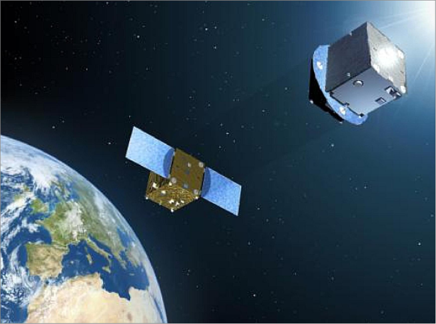
Legend to Figure 38: PROBA-3 will operate in a solar pointing mode with -145 m separation between the two spacecraft. Here a front spacecraft carries an occulting disc, flown on the OSC (Occulter Spacecraft), allowing instrumentation on the rear spacecraft, the CSC (Coronagraph Spacecraft), to make detailed observations of the solar corona with ASPIICS.
Methodology: The scientific objectives will be achieved thanks to broadband imaging of the corona at high spatial resolution and to diagnostic capabilities aimed at characterizing the local plasma (temperature, velocity). While imaging is straightforward, the second capability requires a specific device. Our preferred approach consists in analyzing the bi-dimensional distribution of the spectral profiles of several coronal emission lines (CEL) by a set of quasi concentric fringes generated by the Fabry-Perot etalon interferometer, a technique already implemented during solar eclipses.
To perform a precise line profile analysis far enough out in the corona, the strongest emission line available, the forbidden line of Fe XIV at 530.285 nm, is the prime choice. Additional emission lines will be included to better address different coronal regions as well as a broad spectral channel to image the white light corona and derive electron densities. The fringes have an instrumental profile of typically 0.02 nm, narrower than the width of the line (~0.1 nm for Fe XIV), so that the observed profiles are not significantly affected by the instrumental function and directly give the real profiles of the coronal emission line to a very good accuracy. The etalon will be mechanically tilted to displace the set of fringes and increase the resolution.
General Architecture
The ASPIICS Coronagraph System is composed of the CI (Coronagraph Instrument), the OD (Occulter Disk) and the metrological sensors. The coronagraph instrument itself is composed of the COB (Coronagraph Optical Box), the CEB (Camera Electronics Box) and of the CCB (Coronagraph Control Box). The coronagraph instrument is mounted on the CSC (Coronagraph Spacecraft) while the Occulter Disk is mounted on the OSC (Occulter Spacecraft).
The COB holds the optics, the detector and its radiator, the FDA (Front Door Assembly), the FWA (Filter Wheel Assembly), and the SHM (Shutter Mechanism).
The metrological sensors are the SPS (Shadow Position Sensor) and the OPSE (Occulter Position Sensor Emitter). The SPS is mounted in the COB and its operation is fully integrated in the COB operations. The OPSE (set of LEDs) is mounted in the center of the Occulter Disk and is observed by the instrument.
Optical design: The ASPIICS optical design follows the general principle of a classically occulted Lyot coronagraph. As shown in Figure 39, the external occulter (D1) blocks the light from the solar disk while the coronal light passes around the occulting disk then enters through the circular aperture of the coronagraph (A1). The primary objective (O1) forms an image of the external occulter onto the internal occulter (D2). The image of the surrounding bright fringe is blocked by slightly oversizing the internal occulter. The secondary objective (O2) re-images the entrance pupil (A1) onto the so-called “Lyot Stop” (A3) that blocks the light diffracted by the edges of the pupil. Finally, the corona image is formed by a camera (O3) onto the focal plane (F).
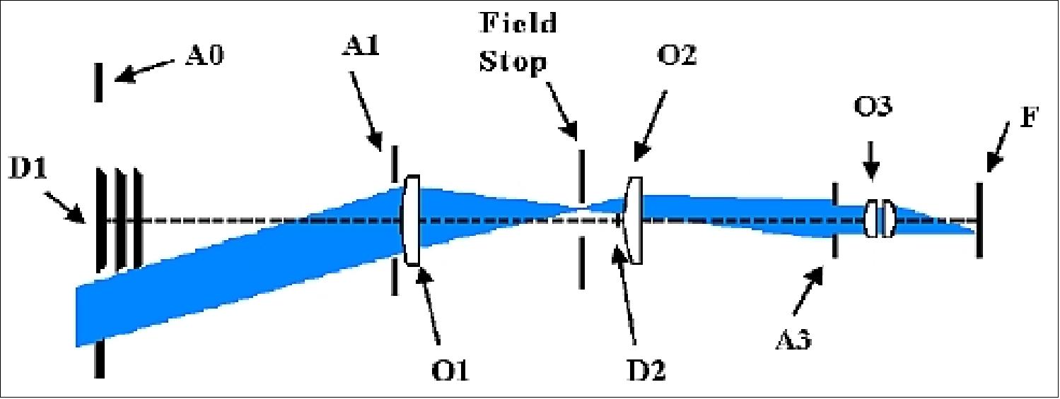
The external occulter (EO), hosted by one spacecraft, blocks the light from the solar disk while the coronal light passes through the circular entrance aperture (50 mm diameter) of the optical telescope on the second spacecraft. As shown in Figure 40, the PO (Primary Objective), located 200 mm behind the entrance pupil, forms an image of the external occulter (EO) onto the internal occulter (IO). The image of the surrounding bright fringe is blocked by slightly over-sizing the internal occulter (1.04 Rs instead of 1.02 Rs). The RL (Relay Lens) re-images both the entrance pupil onto the so-called “Lyot Stop” and the corona image onto the CCD detector (protected by a glass window). The detector is a 2048 x 2048 with 15 µm pixel size. The effective focal length of ASPIICS is 1150 mm with an overall length (from the entrance pupil to the detector plane) of 700 mm.
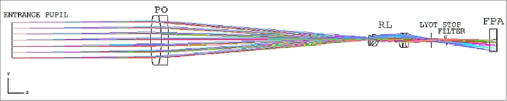
The PO (Primary Objective) is composed of two separated lenses made of radiation resistant glasses to avoid darkening. The relay lens is made of two sets of lenses: a doublet, followed by a lens and another doublet. A filter wheel is inserted after the Lyot stop and contains 4 polarizes and 2 filters: a wide band filter [(540 nm – 590 nm) and a narrow band filter centered on the He I D3 line (587.6 nm)].
Optical design simplification: Initially, ASPIICS incorporated a Fabry-Perot interferometer to perform 3D-diagnostic of the corona. However the limited resource available on the PROBA-3 platforms led the project to descope the Fabry-Perot instrument. This descoping allowed drastic simplifications of the optical design. In particular, the pupil diameter has been reduced (from 140 mm to 50 mm) allowing to replace the TMA (Three-Mirror Anastigmat) by a lens objective (doublet). The doublet preserved the image quality: even if intrinsically it offers lower image quality, by taking into account the manufacturing and alignment errors, the doublet is comparable to the TMA. By using a doublet, the overall optical train can be implemented on-axis and the whole mass is reduced by about 30%. The use of a doublet relaxes the thermal stability requirements of the optical bench.
The primary objective has an effective focal length of 300 mm and is composed of two separated lenses made of BK7G18 and SF6G05. The two lenses are made of radiation hard glasses to avoid any darkening effects while the optical performance are strictly equivalent to those achieved by classical glasses (e.g. BK7 and SF10). The separation (of 0.5 mm at the edge) allows to cope with the differential thermal dilation between the two lenses and allows mounting the two lenses in a common barrel. The primary objective has been optimized for finite distance object (144 m) for a FOV (Field of View) corresponding to the outer edge of the external disc (i.e. ~1.02 Rsun).
Optical specifications | - Telescope effective focal length: 1150 mm |
Detector | - Size: 2048 x 2048 pixels; 15 µm pixel |
Wavelengths / operational modes | - Bandpass 540–590 nm |
Image quality: The optics of ASPIICS shall produce diffraction limited images in both planes of the internal occulter and the focal plane. Indeed the image quality specification is divided in two in order to meet the two main functions of the coronagraph:
1) Image of the corona on the detector which is required to observe the corona with the specified spatial resolution (about 2.8 arcsec/pixel) over the whole FOV (about ±2.7 Rsun)
2) Image of the external occulter onto the internal occulter which is required to reduce the stray light in the instrument.
Figure 41 shows the image quality at the focal plane for an object at infinity up to 0.8º (i.e. 3 Rsun). On the right hand-side, the spot diagram is given for four wavelengths (0.540 µm, 0.555 µm, 0.570 µm and 0.588 µm). The boxes are 30 µm square (i.e. 2 x 2 pixels). On the left hand-side, the plot shows the variation of the RMS spot radius across the FOV for the same four wavelengths. The specifications are met for a circular FoV of 2.7 Rsun and only the corners of the detector (up to 3 Rsun) are slightly out-off specification.
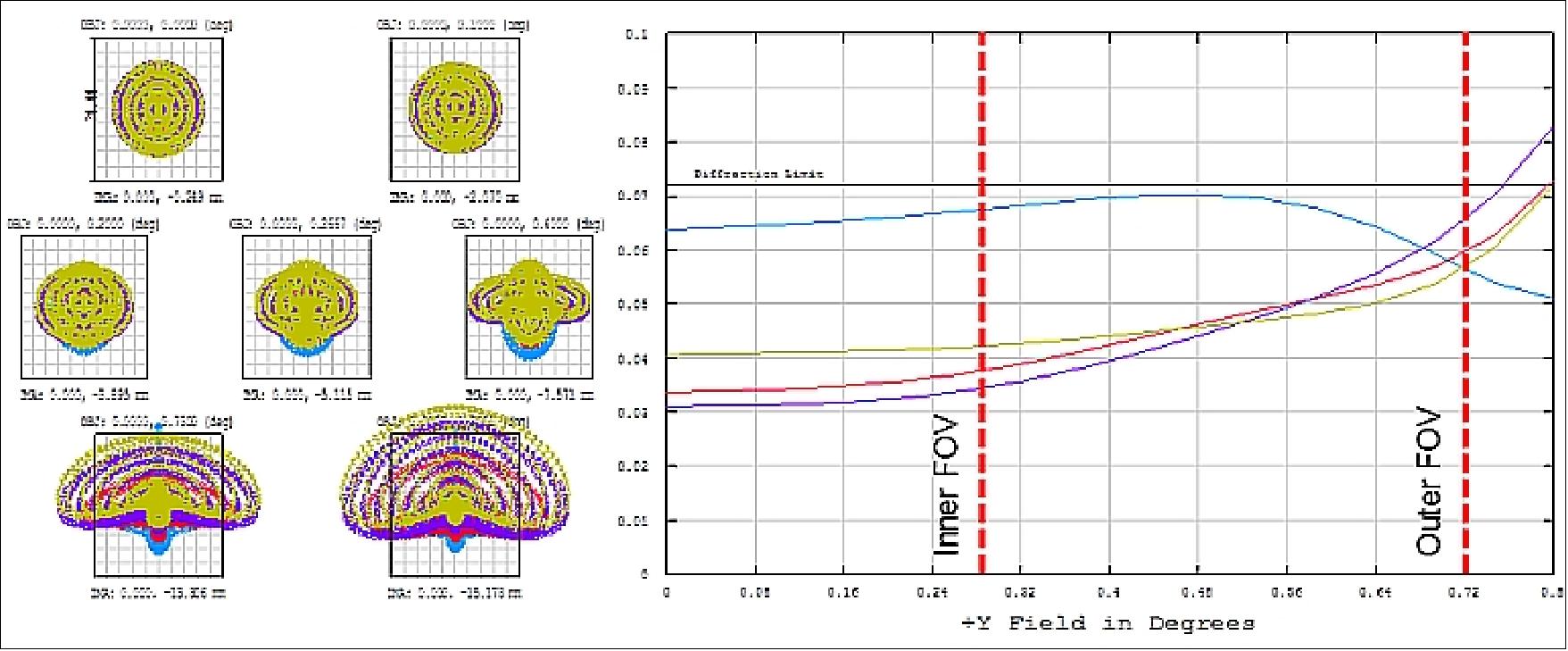
Figure 42 shows the image quality at the internal occulter plane for an object located at 144 m. Indeed, the internal occulter is the conjugated plane of the external occulter. The optimization has been made for a ring of about 1.02 Rsun corresponding to the edge of the external occulter.
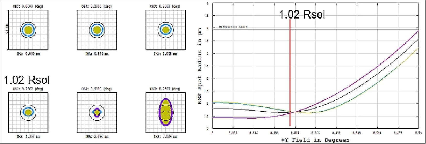
Stray Light Performance
The major source of stray light is the diffraction by the EO (External Occulter) edge of the direct Sun light. Indeed, the intensity of the Sun is several orders of magnitude higher than the corona in visible light; and even if the external occulter blocks the direct Sun light, the light diffracted by its edge remains a major concern and this contribution must be estimated. A computation has been made in two steps:
1) Diffraction by the external occulter based on the Fresnel-Kirchhoff theory at the pupil and the primary objective level.
2) Propagation of the diffracted light in the instrument with ASAP.
Diffraction by the External Occulter: The evaluation of the diffraction pattern on the pupil plane was performed by means of the Fresnel-Kirchhoff diffraction theory. The solar disk can be schematized as a finite set of non-coherent source points. Using 419 points to describe the full disk allows achieving a typical precision of ±1% on the computation of the diffraction pattern. The project neglected all the intensity variations on the solar disks (e.g., sunspots), except for the limb darkening effect.
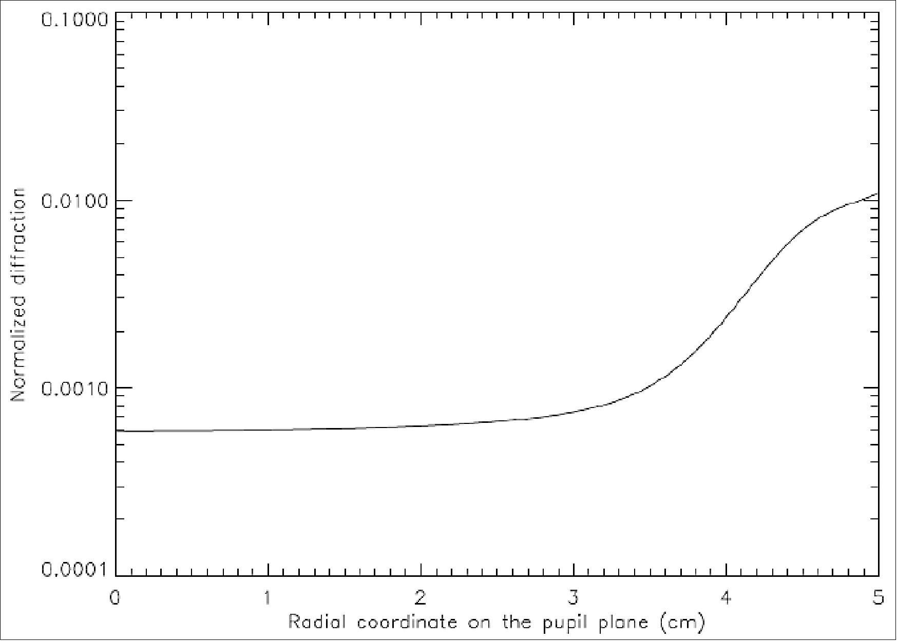
Figure 43 shows the normalized profile of the light diffracted by the external occulter in the entrance pupil plane considering a simple occulting disk. The profile is almost constant (about 6 x 10⁻⁴ with respect to the Sun disk brightness) over the entire entrance pupil. The previous computation has been made assuming a simple disk as occulting system. However, ASPIICS will incorporate a conic occulter edge that will reduce the amount of light diffracted toward the entrance pupil. Experiments to optimize the occulter edge shape have been made in the past (in particular during the second Startiger initiative. In the region 1 Rsun to 1.1 Rsun, it is possible to reduce by a factor 2 to 5 the light diffracted towards the pupil by using a conic shape occulter. This is shown in Figure 44 which plots the ratios between the simple knife-edge (simple disk) and some other occulter shapes (including the cones). The experiments were performed with a set-up replicating a portion of the large occulter (~1.5 m), approximated by a straight edge. The stray light in the solid angle subtended by the ASPIICS pupil was measured.
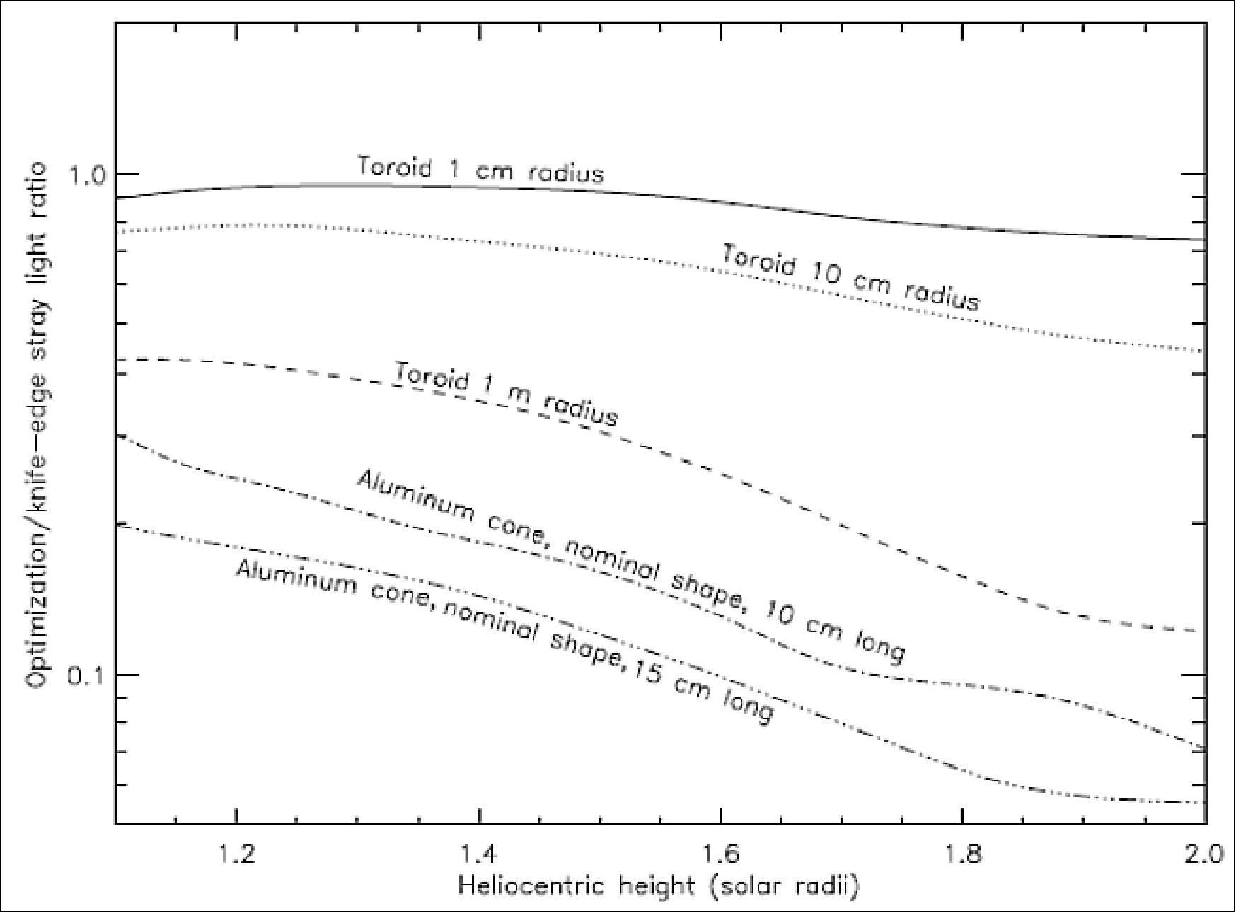
Instrumental stray light: The study was performed with the ASAP® ray tracing software. A view of the mechanical model with the optical elements used for the stray light analysis is shown in Figure 45. This model was used to assess the expected final stray light level on the detector taking into account: optics scattering, ghosts, scattering and reflections by mechanical parts, etc.
Several sources have been considered: in particular, the external occulter, Earth and Moon up to 15º of the line of sight, and reflections and scattering on the rear side of the external occulter. The model allowed the project to propagate the diffracted light through all the optics up to the detector taking into account all effects (scattering, ghosts, etc.). It appears that the scattering of the PO drives the stray light level between 1 and 2 Rsun. Indeed, the IO (Internal Occulter) blocks the direct light from the external occulter but the part which is scattered before (i.e. by the PO) produces a pattern on the detector as shown in Figure 46. Therefore the critical parameter is the micro-roughness of each surface of the PO (Primary Objective).
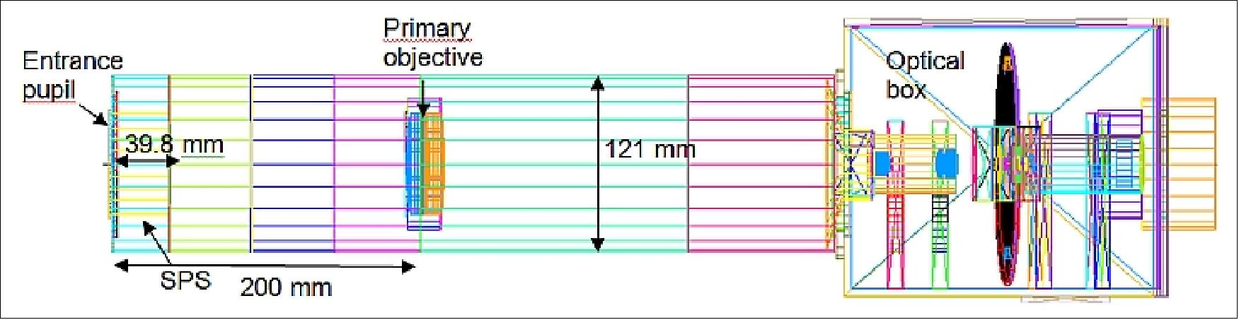
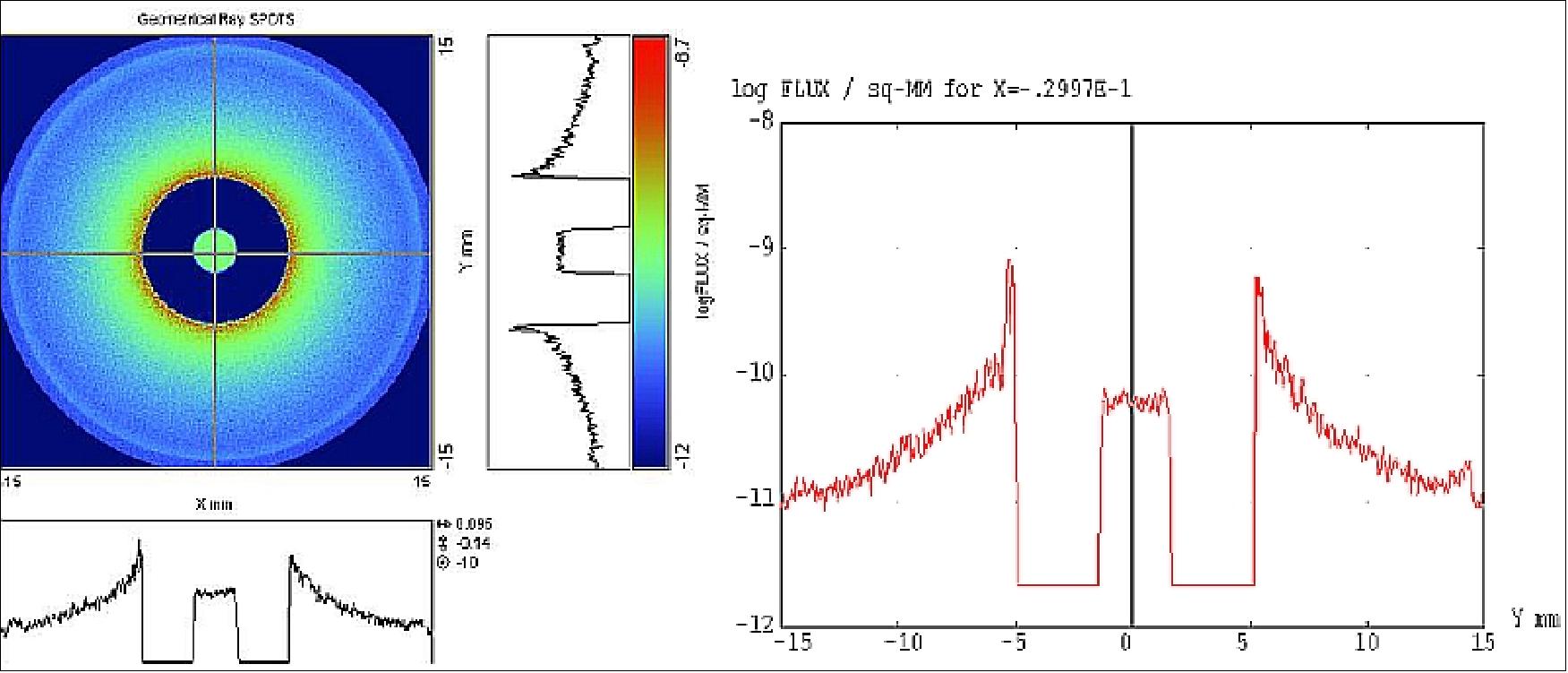
Figure 47 shows the final expected performance considering a micro-roughness of 0.5 nm RMS for each surface. In this case the expected stray light level is compliant with the specification (red lines). Note that if all surface roughness is degraded by a factor 2 (i.e. 1 nm RMS), only the very inner part is significantly affected and the specification is not met below 1.2 Rsun. - Several investigations and prototyping are foreseen to assess the typical micro-roughness that can be achieved on the Primary Objective lenses.
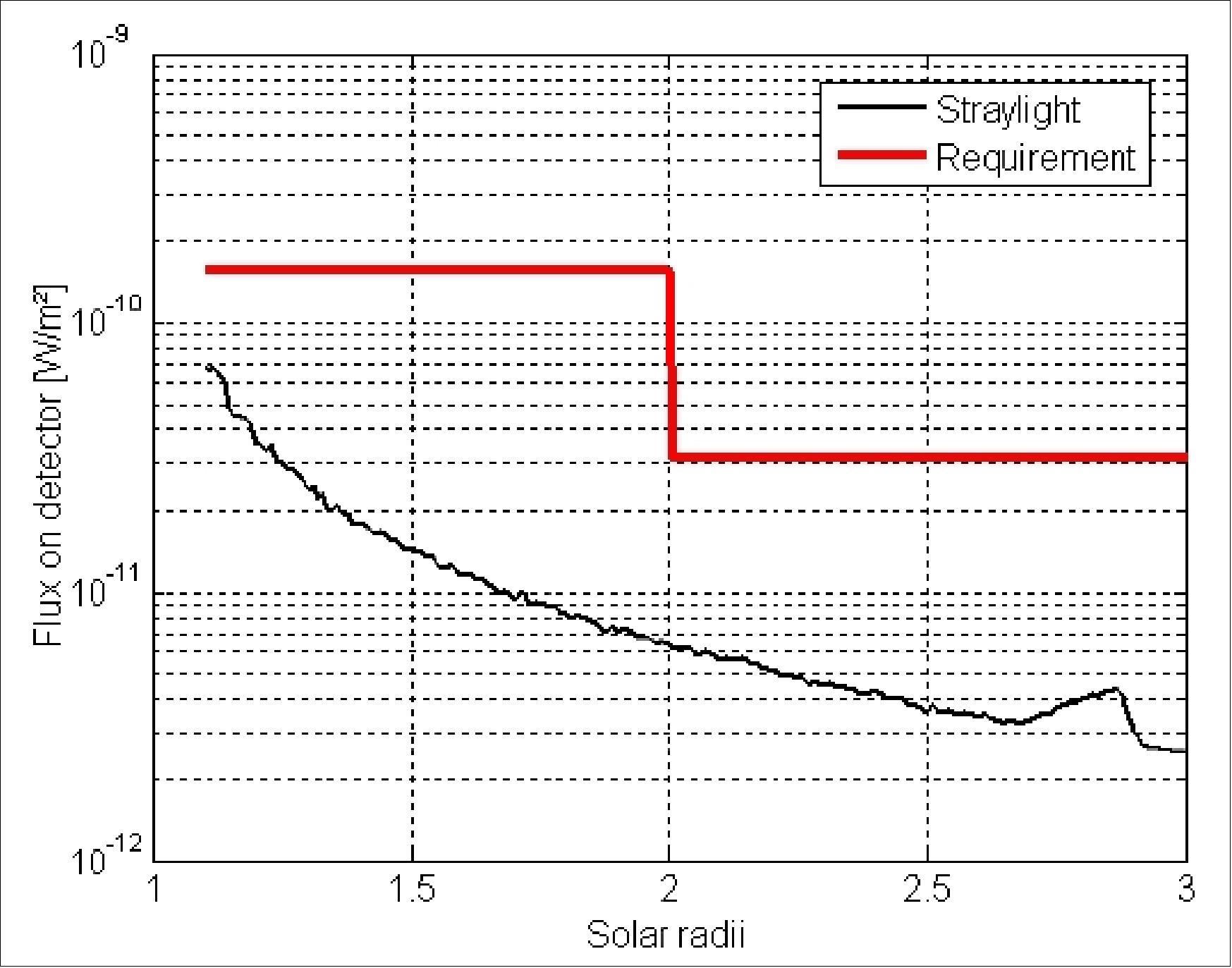
Hence, it has been demonstrated, that the proposed optical design for ASPIICS will allow observing the very inner corona (from 1.04 Rsun) with an unprecedented spatial resolution. Indeed ASPIICS will fully take advantage of the formation flying technique.
ASPIICS COB Hardware Components and Mechanisms
Mechanical and thermal design: The thermo-mechanical concept of the COB (Coronagraph Optical Box) has to preserve the position stability of the optical parts after their alignment. The selected optical design concept with axis-symmetrical dioptric optics and a low f-ratio widely helps this task. The stability required by the optics implies the use of a temperature controlled structure in aluminum alloy, associated to a time-stability of ±2°C. Moreover, with possible temperature gradients inside the instrument structure, the use of a honeycomb panel is rejected for the risk of temperature difference between the two skins, causing potential optical axis instabilities. To minimize thermo-elastic effects inside this structure, and in particular optical axis rotations, a concept based on a full symmetry with respect to skittle plane was privileged. A massive structure is therefore baseline of the project, and shall be dimensioned for temperature gradient effects minimization (Ref. 46).
The mechanical architecture is based on the use of a main structure, supported by three bipods in titanium, interfacing with the OBA (Optical Bench Assembly) of the CSC. The structure breaks down in two main parts, both in aluminum alloy:
• A Tube starting at the entrance pupil, and ending just before the focus plane of the first imager. It supports the SPS (Shadow Position Sensor), the FDA (Front Door Assembly), and the entrance objective (the entrance pupil diaphragm is a part of the SPS) at the entrance end, and the IO (Internal Occulter) with field stop at the other end. Several optical vanes are distributed inside, to trap the stray light.
• A structured parallelepiped called EQB (EQuipments Box) supports, the relay lens(es), the FPA and its radiator, as well as the filter wheel and the Lyot stop assemblies, the shutter mechanisms, and the venting systems. A lid will cover this structure, to prevent dust pollution. The venting systems with a protection against stray light and the electrical connectors interface complete the equipment of the EQB.
The three bipods support the above structure: two front monopods interface with the Tube while both rear bipods interface with the EQB, symmetrically disposed. The shape and size of these bipods have to be carefully calculated to:
- ensure the system rigidity and required first eigenfrequency of the COB
- minimize the mechanical constraints resulting from temperature gradients between the coronagraph structure and the supporting OBA
- minimize the transfer of OBA deformations (and resulting stresses) to the coronagraph structure
- minimize the thermal conductive leaks between the COB and the OBA.
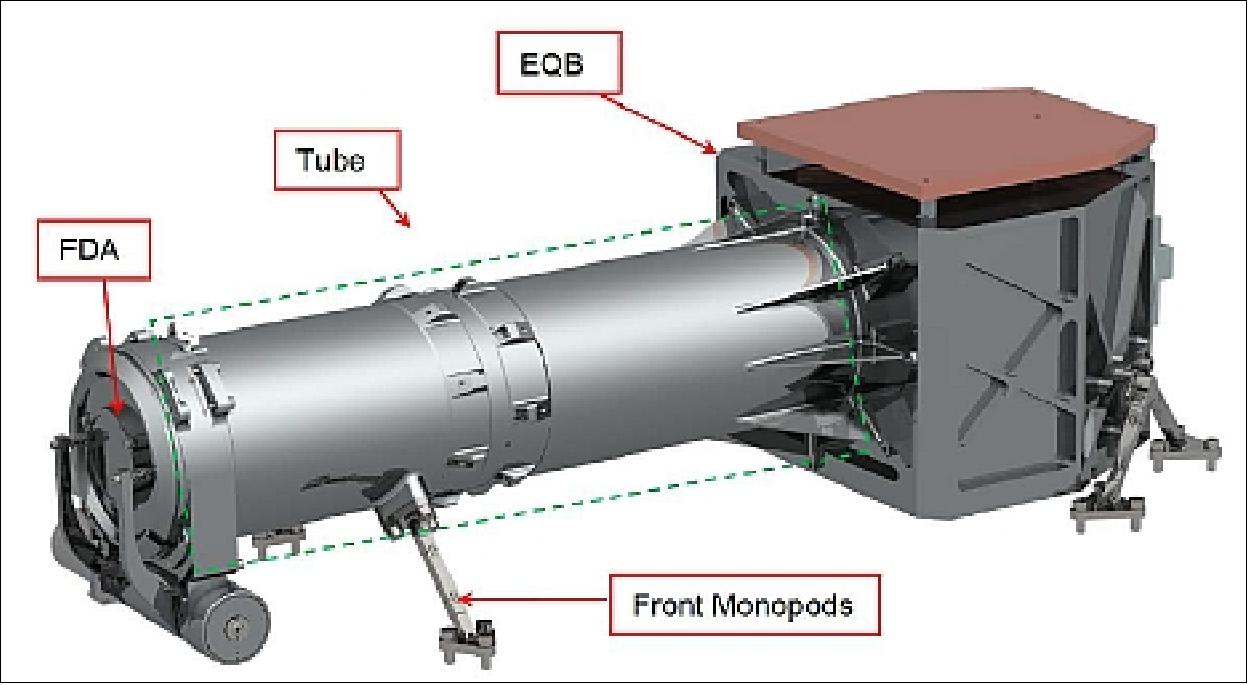
FDA (Front Door Assembly): The protection of the instrument against dust particles, during the storage and especially during the launch phase requires to use a protection door. Moreover, the presence of this door allows possible photometric calibrations of the instrument by use of a HDD (High Density Device) fixed in the center of the door, and, when lighted by the Sun, produces a flat field image on the detector. The FDA allows a several shot closing/opening of the entrance aperture by the use of a mobile lid moved by a stepper motor in normal conditions. This lid is only opened at the beginning of the observation period and closed at the end. As a redundancy, in case of a failure of this actuator, a one-shot wax actuator allows the definitive opening of the lid.
FWA (Filter Wheel Assembly): The several possibilities of observation - in a wide bandwidth, in a narrow bandwidth and in polarized light - force to use a motorized filter wheel with 6 positions: narrowband filter, wide-band filter, and 4 polarizers. These filters, mounted on the wheel, are inserted in the optical path close to the secondary pupil of the system, and tilted to avoid ghost images on the detector. The FWA consists of a wheel moved by a stepper motor / gear box with reduced backlash which positions the filters in the optical beam. The position is read thanks to a set of position sensors.
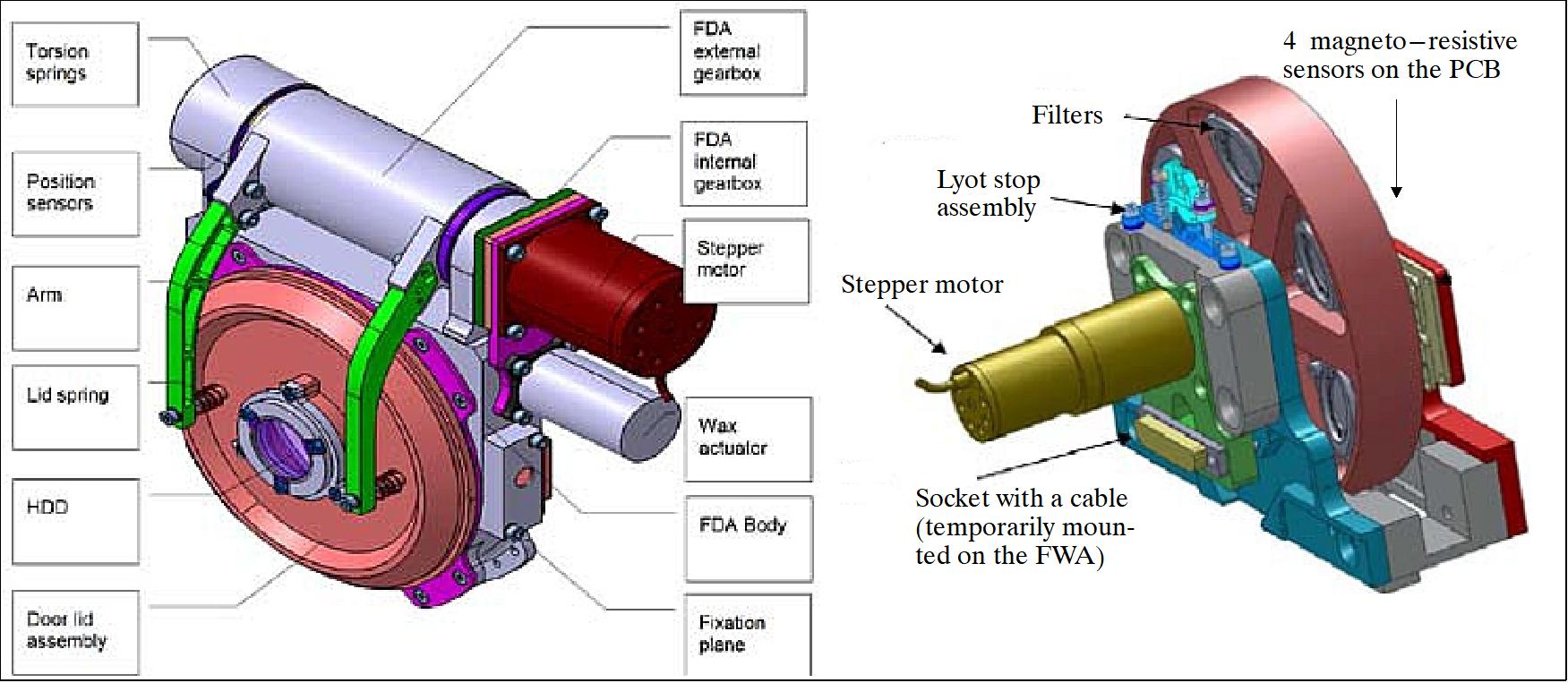
SHM (Shutter Mechanism): A mechanical shutter, under form of a blade, is linked to the use of a full frame CCD with short exposure times, and is needed to define the exposure time. It is located close to the intermediate focus and not close to a pupil as usual, because pupil planes are used by optical parts (field stop and Lyot stop).
This particular location allows a protection of the back end of the instrument against full Sun light when the shutter is closed. In this case, the Sun light is blocked by the shutter blade and the corresponding heating power (lower than 0.5 W with full Sun in the wavelength bandwidth of the coronagraph) will be mainly reflected and absorbed by the baffle and tube. All the sensitive parts behind the primary focus are then protected, and the only lighted part is the entrance objective, which can survive to this potential event. To complete the protection, the shutter will close automatically when unpowered, by action of a spring on the shutter blade. With this system, even in case of power failure, the instrument can support a long exposition to full Sun.
The mechanism uses a limited angle DC brushless torque motor, directly mounted on the shutter blade axis. This blade is in the closed position when unpowered, and maintained open by a small electrical current in the motor during the exposure time. The rotational spring is only used for closing the shutter when this current is suppressed. In normal conditions, the control loops ensure this movement. A position encoder completes the hardware to realize a highly reproducible movement.
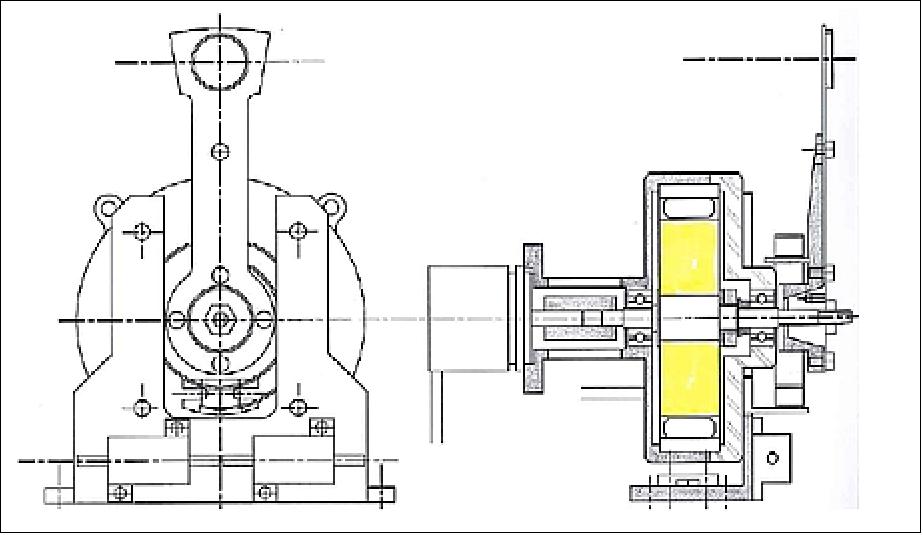
SPS (Shadow Position Sensor)
The SPS verifies the safe centering of the entrance pupil of the coronagraph into the shadow cone of the occulting disc. Initially planned for a high sensitivity relative measurement of the umbra location with reference to the center of the entrance pupil of the coronagraph instrument, it has evolved towards a sensor giving an absolute location with a high accuracy. Another function required of the SPS is to signal to the satellite (CSC) that the umbra moves out of the nominal position range of the SPS, this is to prevent the risk of the full Sun inside the coronagraph instrument.
The SPS is based on the use of light sensors disposed around the entrance pupil diaphragm of the coronagraph. All sensors are located close to the pupil diaphragm and then, in the nominal flight configuration, in the penumbra zone given by the external occulting disk. For practical reasons (space around the pupil, redundancy, accuracy), the project disposed 8 light sensors, organized in 2 groups of 4 sensors. The sensors of a group are equally distributed on a circle centered on the entrance pupil center, and two circles with respective radii of 42 and 52 mm have been selected for the two groups.
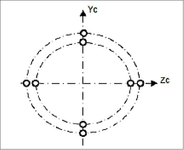
A sensor in the penumbra sees the light coming from a crescent of Sun. The surface of this crescent is nearly linear with the decent ring if it stays sufficiently small. Therefore, the light received by this sensor evolves nearly linearly with the distance with the full umbra, and the principle of measurement is based on this particular property.
As the photon current of a photodiode is perfectly proportional to its illumination, the voltage signals delivered by the front-end electronics and then digitalized are nearly proportional to the umbra displacements, except when they are in the full umbra of the occulting disc. Considering two opposite sensors, they are never in the umbra at the same time, and photometric information is always available.
The SPS head is a compact sub-system which is mounted in front of the instrument Tube, under the lid of the FDA (Front Door Assembly). Figure 52 shows the main parts of this head.
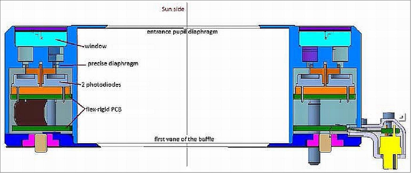
The head includes the 8 sensors distributed on two circles with respective radius of 42 mm (sensors #1) and 52 mm (sensors #2). They are mounted on a PCB (Printed Circuit Board) in flex-rigid technology (2 rigid annular parts connected together by a flex circuit and connected to an in/out connector). These two rigid parts of the PCB are mechanically mounted on the base plate (in dark blue) thanks to a set of screws and spacers. The PCB also includes the operational amplifiers, and small components needed to condition the current signals delivered by the photodiodes.
OPSE (Occulter Position Sensor Emitter)
The objective of the OPSE is to verify the positioning of the occulting disc in the FOV of the coronagraph that is the alignment of both spacecrafts independently of the pointing to the Sun.
The OPSE device consists of a set of 3 light emitters mounted on the rear side of the external occulting disc. Their images produced by the coronagraph have a characteristic pattern that uniquely defines the position along the transverse axes, with respect to the instrument coordinate system. Moreover an estimate of the intersatellite distance (ISD) and of the orientation of the external occulter is also provided.
The 3 OPSE elements are located close to the center of the disk, limiting in this way the size of the density hole in the center of the Internal Occulter in the coronagraph. The images are received by the CCD of the coronagraph which, after readout, can be sent to the ground for analysis. The information delivered by the OPSE is therefore not usable onboard in real time.
The use of the OPSE supposes a coronagraph fully operational, door open, and then with the entrance pupil in the umbra or low penumbra; this last point limits its use. The drive electronics is a part of the satellite, the coronagraph team has only to propose the architecture of this electronics and the corresponding requirements.
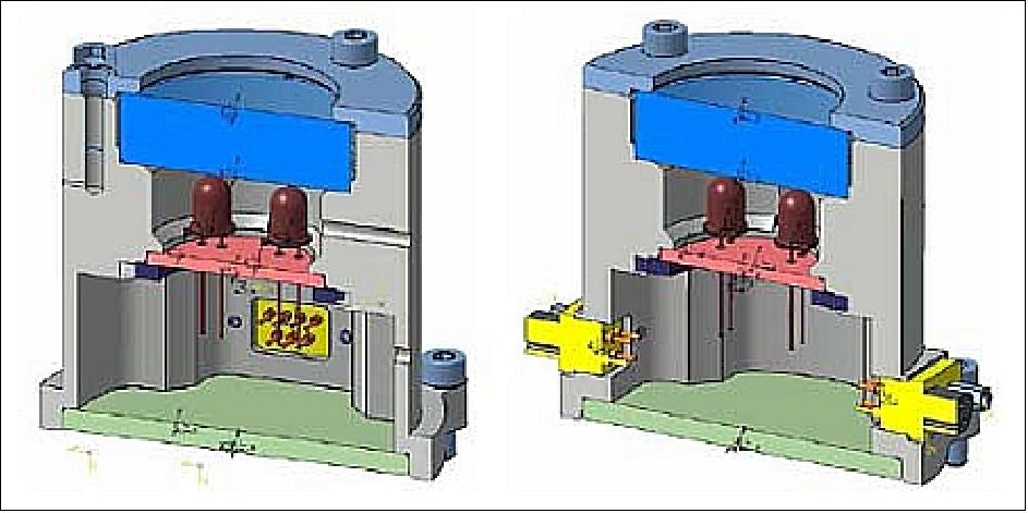
ASPIICS CCB (Coronagraph Control Box)
The instrument electrical design approach integrates the CCM (Coronagraph Control Module) together with MCM (Motor Control Module), AEM (Ancillary Electronics Module) and PCM (Power Converter Module) in a central CCM (Coronagraph Control Box) to achieve a highly compact and efficient design. The CCM together with an integrated mass memory provides sufficient computing resources to cover both, command & control of the complete instrument as well as sophisticated image data processing. This includes the interface handling towards the spacecraft, housekeeping data acquisition, automatic image data acquisition & processing, and execution of autonomous measurement sequences. 55)
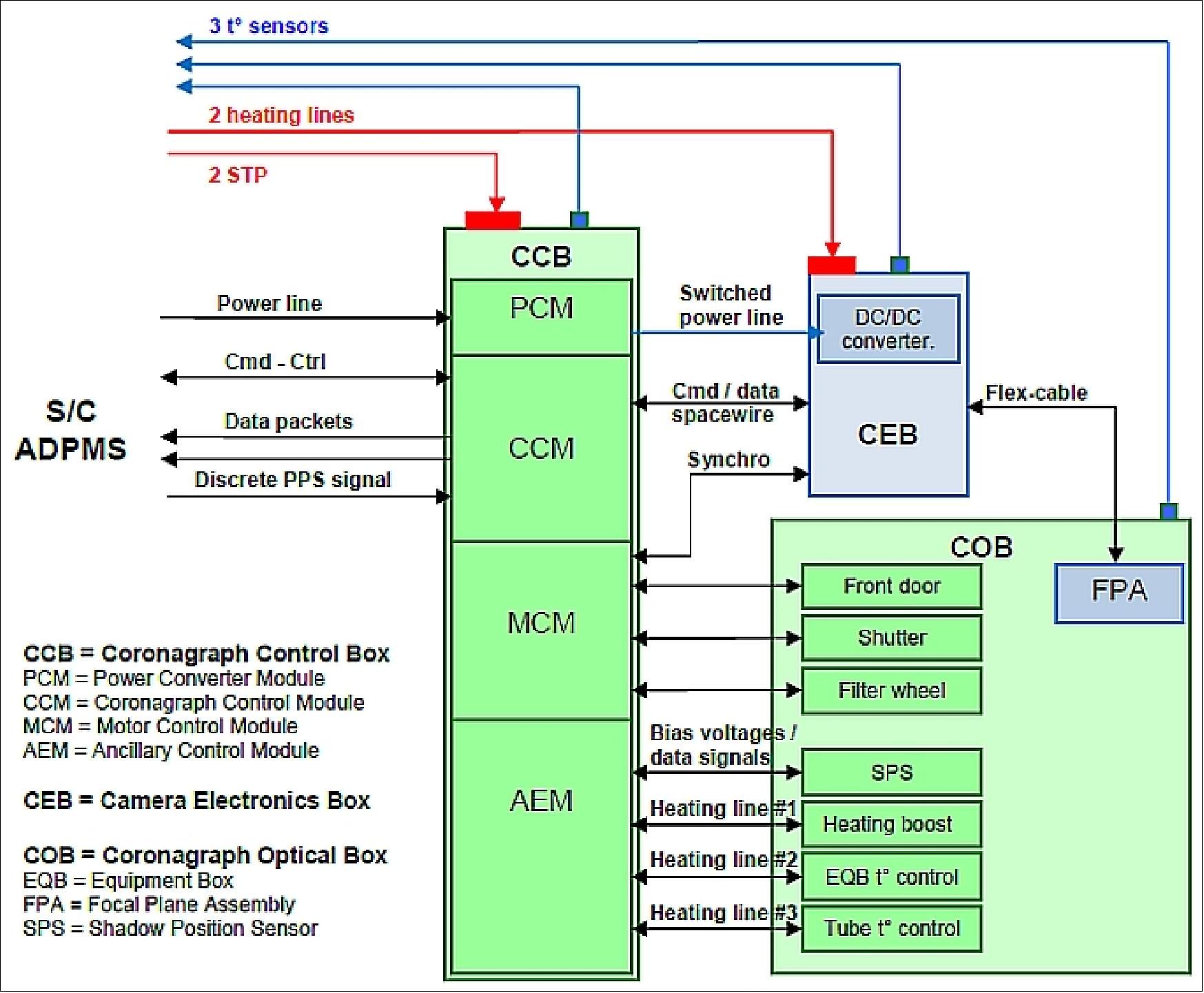
The CCB consists of a metallic box that houses five individual electronic modules and it has the central role controlling all the activities of the coronagraph instrument subsystems while being the only I/F with the spacecraft, for commands, controls or data exchanges. The electronic modles, PCB cards, are mounted on separate metallic brackets (Figure 55). The modules are interconnected through a backplane unit which is designated as the motherboard module of the electronic system. The backplane is also supported to a metallic plate, designed in order to withstand the required operational and vibrations loads.
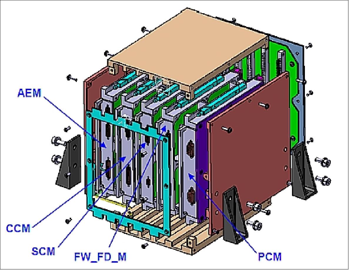
CCM (Coronagraph Control Module)
The design utilizes a combination of a LEON-3 based main processor system within a fixed, radiation hardened and TMR by design, one-time programmable FPGA (Microsemi RTAX) together with a dedicated data compression function core implemented within an in-flight reconfigurable FPGA (Xilinx Virtex). Since all data processing steps are performed by dedicated FPGA hardware, the moderate processing power (20-30 MIPS) of the LEON-3 processor is sufficient for overall high-level instrument control and for communications with the spacecraft platform.
The processor will control and synchronise the camera electronics, the SPS (Shadow Position Sensor), the thermal control and the mechanisms control, including shutter, front door and filter wheels. All interfaces and instrument control/monitoring functions needed for basic operations are integrated in the fixed area FPGA to achieve highest reliability. Additionally, this FPGA acts as system supervisor to achieve the configuration control and required SEE radiation tolerance of the reconfigurable FPGA, supported by a high-reliable configuration memory for firmware storage.
The limited telemetry rate combined with the large amount of scientific information retrieved from the camera system demands sophisticated on-board data compression. This is achieved by a dedicated, in-flight reconfigurable processing core attached to the running system by a flexible and glitch-free on-chip communication architecture, named SoCWire (System-on-Chip Wire). The SoCWire is based on the well established ESA SpaceWire interface standard. Such a reconfigurable system is currently developed at IDA (Institute of Computer and Network Engineering) of the Technical University Braunschweig in the frame of the ESA DRPM (Dynamically Reconfigurable Processing Module) study.
On-board image data compression is based on the CCSDS-122.0-B-1 IDC (Image Data Compression) algorithm. The CCSDS-IDC is implemented as a reconfigurable core in a high density, space qualified reconfigurable FPGA which provides an excellent dynamically reconfigurable on-board payload data processing solution, featuring high reliability (with configuration memory scrubbing), high performance and high circuit density. The CCSDS-IDC core architecture provides a powerful, cost-effective and highly integrated solution since it does not require any external memory.
A complete non-volatile reliable mass memory system, providing significant storage capacity fulfils all needs of intermediate data storage at very low resources need. According to the proposed observation strategy, an anticipated memory capacity of 256 Gbit is more than sufficient and leaves ample capacity for future changes. For high data rates, it is directly controlled by a DMA-type of flash memory controller within the RTAX FPGA.
The design of the NAND-Flash based system will have complete error correction, taking into account the Flash handling. NAND-Flash based mass storages for space have been intensively studied by IDA in the SGDR (Safe Guard Data Recorder) study by ESA and are currently under development for the Sentinel-2 SSMM (Solid State Mass Memory).
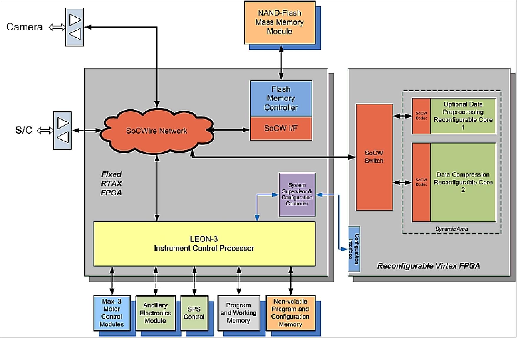
PCM (Power Control Module)
The CCB is the first equipment which is switched on after an OFF mode, by activating the only power line delivered by the spacecraft. This primary line powers the DCDC converter inside the PCM, and in particular, the CCM (Coronagraph Control Module), which, after the short time for boot and initialization, is able to manage the distribution of primary or secondary power to the others modules.
A power distribution unit is effectively included inside the PCM, which has to provide the following functions:
- to deliver the primary power to the Ancillary Electronics Module (AEM) to power the heaters needed for COB warming, thanks to the dedicated amplifiers
- to power the camera by a switch-on of the primary power line for the CEB, on order from the CCM
- to deliver the primary power to the MCM (Motor Control Module) to power the pin puller inside the FPA (Front Door Assembly) thanks to a dedicated switching system
- to deliver the primary power to the MCM after a short time needed to initialize circuits of motor controllers: this avoids the risk of motor jump at switch-on.
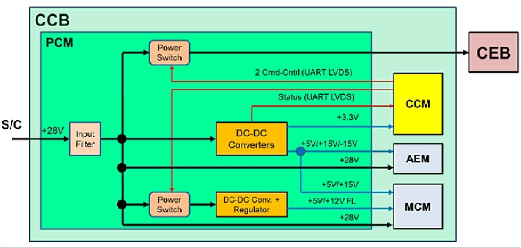
AEM (Ancillary Electronics Module)
The AEM is a module of the CCB. Its two main functions are:
- the acquisition and treatment of the data delivered by the SPS head (front head electronics close to the pupil of the instrument), before a transfer to the CCM
- the temperature control of the 2 controlled zones of the COB: the tube and the EQB. An additional heating line takes advantage of a CEB off to use the corresponding power to boost the heating for a faster heating.
The AEM receives from the SPS head 8 differential signals coming from the 8 light sensors and 2 temperature signals. It has to power the SPS head by a symmetrical power supply. The differential signals are received by instrumentation amplifiers, followed by two double multiplexers authorizing the selection of two signals at a time on the eight received from the SPS head. These two signals are digitized by two 16 bit ADC at a cadence of 40 samples/s, prior to the transfer to the CCM for a final treatment in software.
The temperature sensors needed by the SPS (2 in the head and 2 close to the ADC) are also conditioned by the AEM. The second part of the AEM is dedicated to the temperature control of two zones:
- the front tube of the COB
- the Equipment Box of the COB.
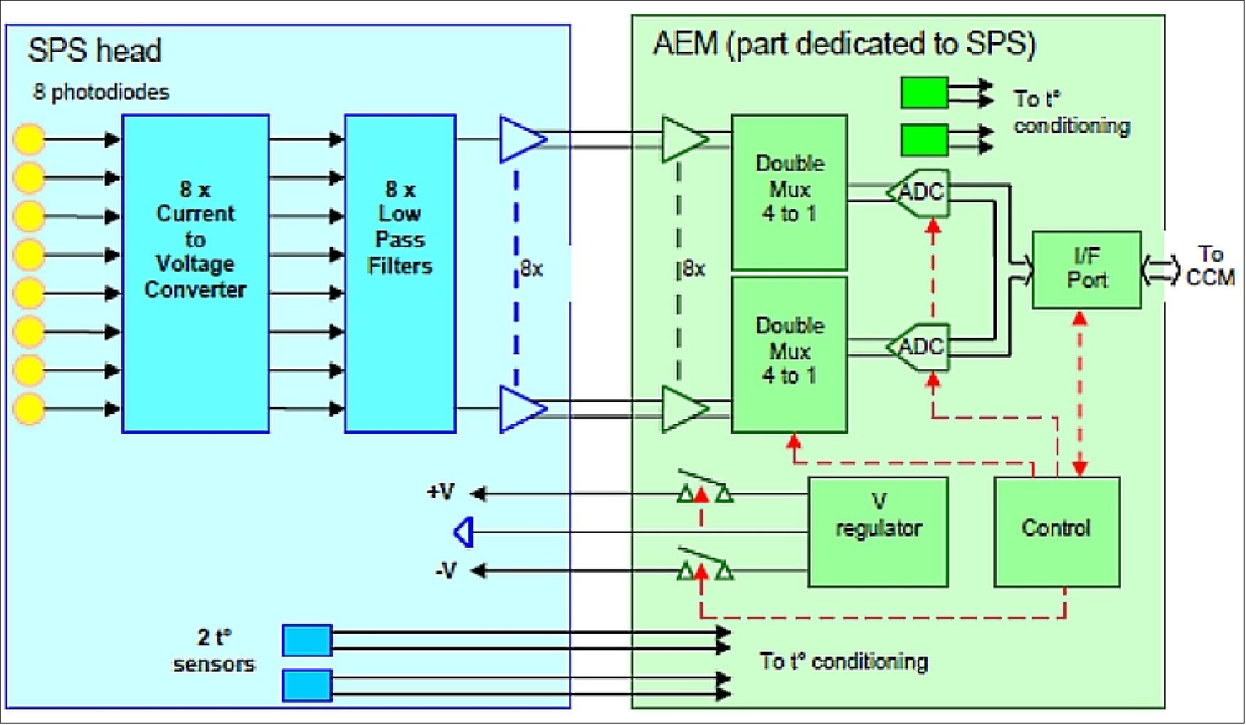
The second part of the AEM which is dedicated to the temperature control of two zones (the front tube of the COB and the Equipment Box of the COB) is shown in Figure 59. The temperature control of each zone is achieved by a comparison of the temperature order received from the CCM and the effective temperature measured in the zone. Two temperature values are received from the two temperature sensors mounted in the zone. Differences between these two temperatures (order and effective) are amplified in a PID controller and converted in a pulse width modulation at a fixed frequency of 20 Hz (controller and PWM are in software) and finally amplified to power the heaters of the zone. Two heaters and two power amplifiers are used for redundancy aspects. All temperature sensors are received by two multiplexers to avoid a single point of failure, amplified (2 amplifiers) and digitized (2 ADCs) to 12 bits.
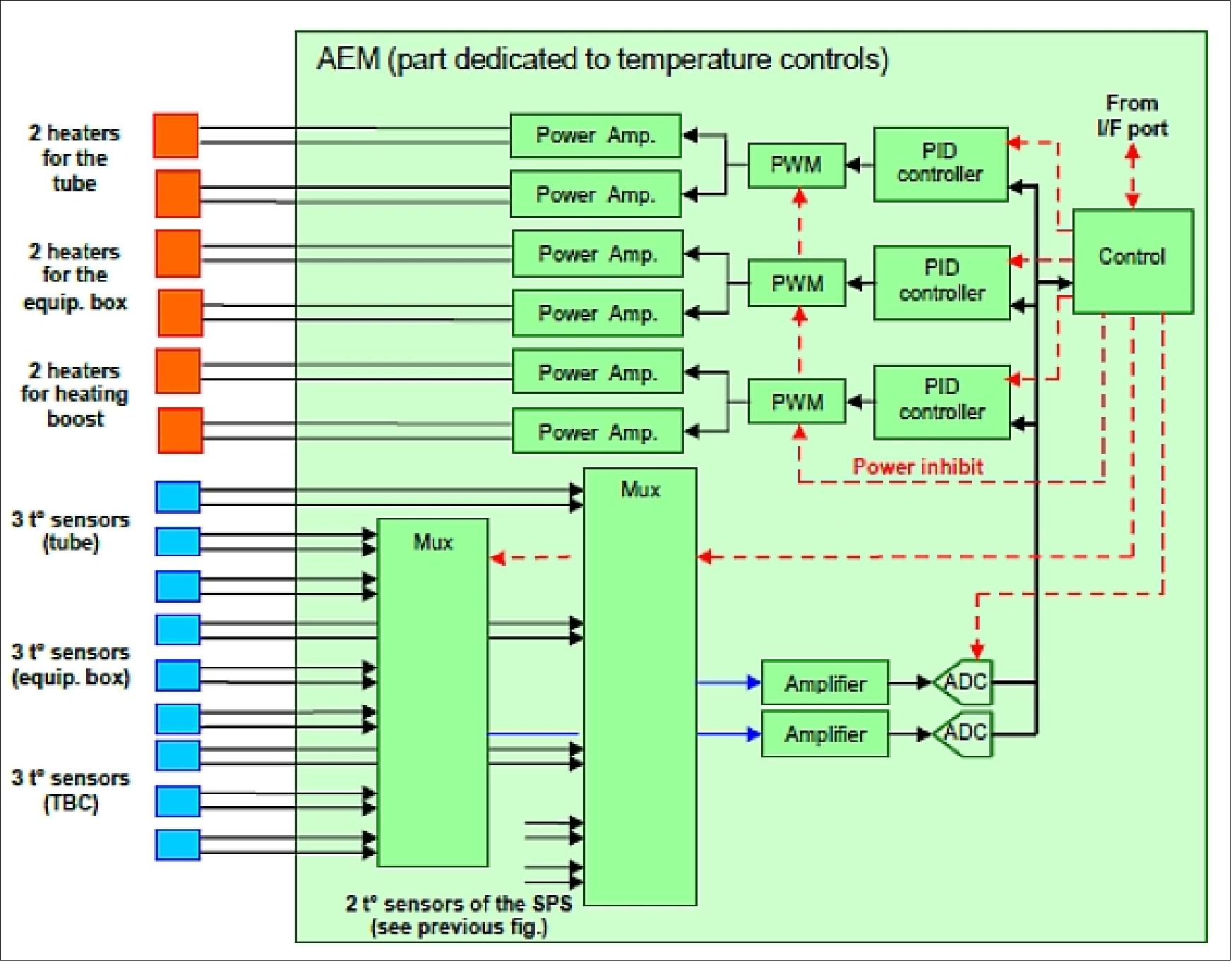
MCM (Motor Control Module)
The MCM has to command and control the activities of all motors inside the COB:
- the Filter Wheel Assembly stepper motor
- the Front Door Assembly main motor, which is a stepper motor, and a pin puller system able to open the door in case of failure of the main motor
- the SHM (Shutter Mechanism), using a DC brushless, limited angle torque motor.
This subsystem includes the motor drivers, the position sensors acquisition and conditioning electronics, and all circuits needed to control the position or speed loops. It interfaces with the CCM thanks to a LVDS link. This module receives from the CCM all orders for mechanism activations, controls the motors accordingly, and sends back to the CCM the new positions reached by the mechanisms. Only one "intelligent" circuit is used for the 3 motor controls, which are fortunately never running at the same time, greatly helping the design.
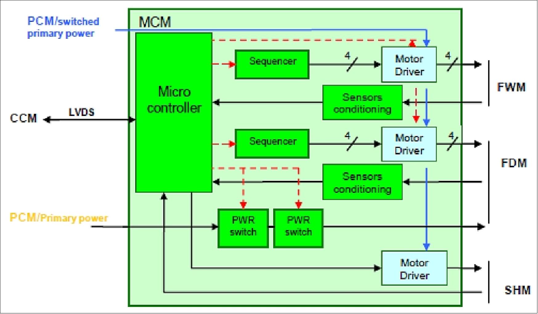
ASPIICS CEB (Camera Electronics Box)
The primary function of the CEB is to operate the CCD, digitize the image data and transfer it to the CCM. An overall schematic diagram is shown in Figure 61. The FPGA is the core of the CEB, this receives commands from the CCM. It generates all the clocks necessary for driving the CCD and drive the DACs responsible for providing the bias voltages.
Image data from the CCD is read out serially and alternated through 2 separate 16 bit ADCs (Analog Digital Converters). The digitized data from these ADCs is then read back into the FPGA where it is assembled into Spacewire packets and transmitted to the CCM. Moreover, the CCD activity will be synchronized with the shutter displacements to preserve the stability of the exposure time of successive images. This is also performed by the FPGA.
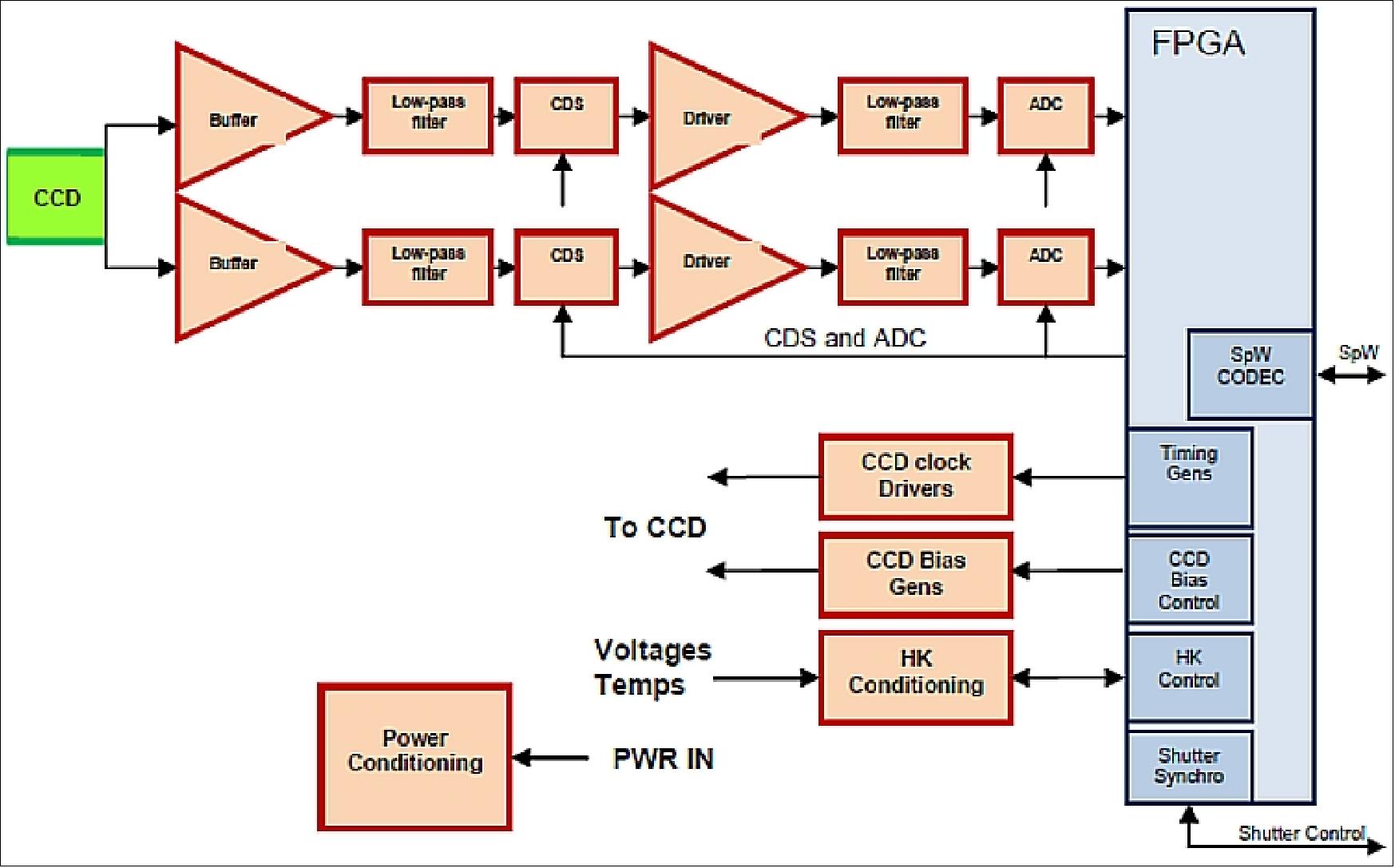
Software Architecture
The S/W of ASPIICS draws substantial heritage from instrumentation on earlier missions, where a similar approach was implemented (SOHO-SUMER, ROSETTA-OSIRIS, VENUS EXPRESS, ...) and successfully run. The architecture is based on a RTOS (Real-Time Operating System) and foresees three layers plus a boot loader that resides in fixed memory. The approach is based on a RTOS and includes a dedicated OCL (Onboard Command Language), a compiler/interpreter system with a full C-like language set and macro-commands for functions specific to ASPIICS. OCL provides a flexible, safe, and easy to use implementation of in-flight reprogrammable procedures. The OCL is inherited from various ESA/NASA instruments and satellites application SW. The three major layer structures of the approach with the following sub layer functions are depicted in the Figure .
Layer 1: Low Level S/W
- Interface to the H/W with the next higher S/W level
- Real-time operating system and driver software
- I/Fs to both the RTOS and the driver S/W. All S/W I/Fs above this level shall be H/W independent.
Layer 2: RTL and Middleware
- Command execution, also within several operational modes
- Basic controlling functions, as so called RTL, e.g. for control of data processing, HK acquisition, etc. Also, control of file operations to and from image memory shall be allocated in the RTL.
- Autonomous, time- and event-driven, flexible, and safe instrument control system, OCL (On-board Command Language).
Layer 3: Application Layer (in OCL)
- High level application software, which is developed using the OCL functionalities, e.g. configurable management procedures for mode sequencing, data acquisition and processing sequencing, autonomous reactions on HK or data evaluation events, etc.
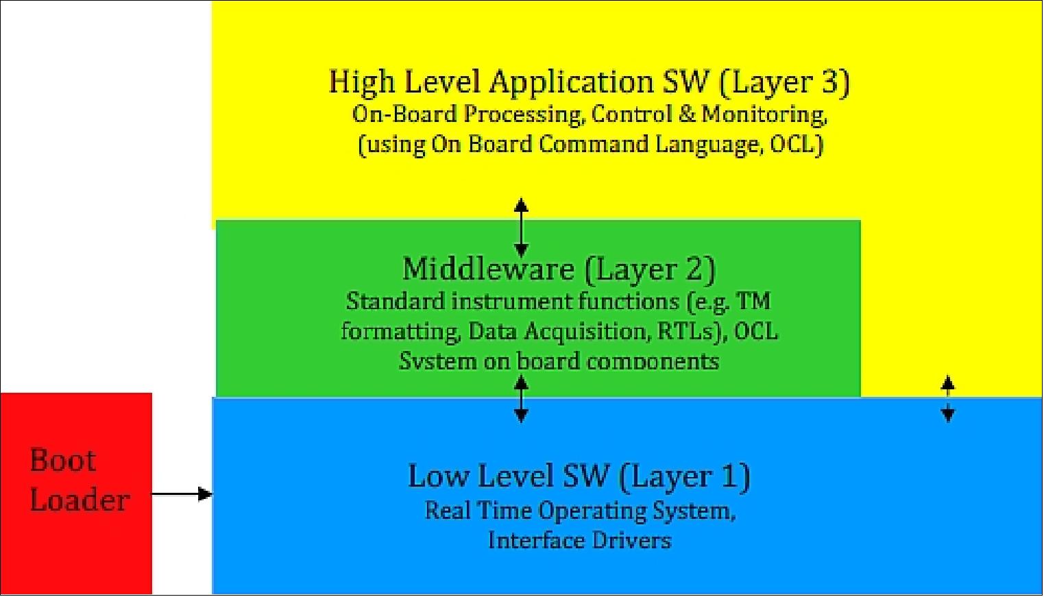
P3RVX (PROBA-3 Rendezvous Experiment)
For several years, there has been a continuing interest on the development of the GNC (Guidance, Navigation, and Control) functions associated to RV (Rendezvous) and FF (Formation Flying) scenarios, that has driven the need to increase the TRL (Technology Readiness Level) of the technologies required to successfully accomplish future planetary exploration, scientific, in-orbit servicing, and ADR (Active Debris Removal) missions. 56)
The PROBA-3 mission also offers a unique opportunity to test other technologies, including to perform RDE (Relative Dynamics Experiments). The P3RVX takes advantage of this opportunity to exploit the suitability of PROBA-3 for the maturation of RV technology, in particular with non-cooperative targets, with two satellites, in a highly elliptical orbit (perigee and apogee height of 600 and 60,530 km, respectively), using optical Navigation.
The P3RVX consortium is led by DEIMOS and includes the Technical University of Denmark (DTU) and University Politehnica of Bucharest/Institute of Space Sciences (UPB/ISS). This paper provides an overview of the P3RVX, which aims to perform in-orbit demonstrations of the Guidance, Navigation, and Control (GNC) subsystem (including the Fault Detection, Isolation, and Recovery (FDIR) functions), the operations, the autonomy approach, and the Verification and Validation (VV), for missions in highly-elliptical orbits with fast and time-varying dynamics. This includes, in addition, the in-flight testing of DTU's Vision Based System (VBS) software for non-cooperative scenarios.
A set of experiment objectives and requirements are foreseen for the P3RVX, as follows:
• The complete RV approach shall be performed in an uncooperative manner and only using a vision-based sensor (except for FF-RVX handover or experiment preparation segments). The chaser S/C shall receive no active help from the target, and no active optical beacons or mires can be used.
• The maneuvers shall begin with the chaser inserted in a relative trajectory that does not advance towards or retreats away from the target over multiple orbits.
• The far- and close-range RV maneuvers (hops) shall be passively safe.
• The maneuvers shall begin at a sufficient distance, so that the target is only identified as approximately a single pixel in the camera detector.
• It shall demonstrate non-cooperative forced motion maneuvers in closed-loop GNC, including hold, approach, retreat, and target inspection maneuvers.
As an additional set of drivers for the RVX design, the following guidelines should be followed within the PROBA-3 experiments context:
• The RV and FF experiments shall be totally complementary, without duplicating effort and results;
• The RV experiment should not imply major constraints or hardware changes in the PROBA-3 baseline;
• The RV experiment shall make maximum reuse of available equipment and system resources;
• The RV experiment shall not represent a risk to the mission.
Apart from these guidelines, a set of mission constraints provide the admissible envelopes for RVX design. These constraints to the RV experiment are inherited from the FF mission, whose main objectives are independent of the technological experiments. Also, the selection of the RVX equipment is based on the needs of several systems. In particular, the Vision-Based System (VBS) and its cooperative modes will be shared with other mission users, for purposes other than the development of RV solutions, which imposes an additional set of constraints.
The spacecraft considered in the PROBA-3 mission are derived from ESA’s PROBA (Project for Onboard Autonomy) platform, and consist of a chaser, the CSC (Coronagraph SpaceCraft), and a target, the OSC (Occulter SpaceCraft), (Ref. 22). The roles of chaser and target S/C are reversed, however, in the FF part of the mission. The spacecraft designation is motivated by the main scientific demonstration, where the OSC includes a 1.4 m occulting disk on one of its facets, and the CSC carries a coronagraph instrument, for observation of Sun’s corona during artificial eclipse.
The CSC and OSC fly a highly elliptical orbit (600 x 60530 km), with a period of about 19.7h, whose high eccentricity is required to achieve low perturbation of formation flying at apogee, as otherwise high-thrust authority would have been necessary. In nominal formation conditions, the CSC and OSC rotating body frames, CRBF and ORBF respectively, are (ideally) parallel to each other, and the corresponding x-axes are oriented along the relative motion line (Figure 63).
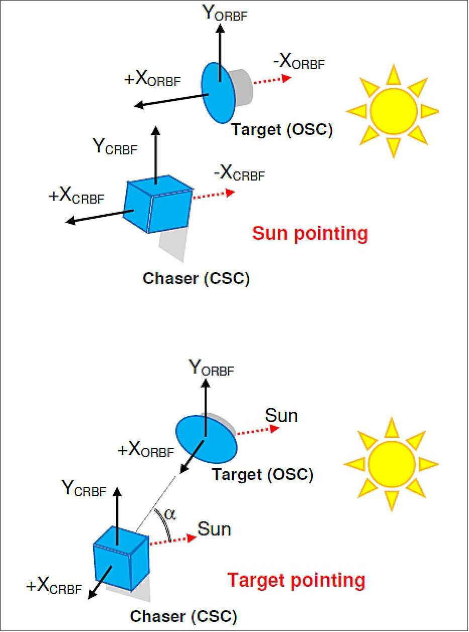
During the RVX, the target (OSC) will carry the camera sensor and is translationally passive, while the chaser (CSC) will perform relative position control. This is a somewhat unconventional layout that is justified by the fact that the camera is mounted on the OSC as per the nominal mission design (which cannot be modified for the sake of the RVX alone), and also by the fact that the CSC needs to act as the chaser spacecraft, as it is the only one with sufficient actuation authority to perform the required maneuvers through the strong-dynamics perigee environment. The camera measurements are relayed back to the CSC through the communications Inter-Satellite Link (ISL), connecting the two PROBA-3 spacecraft. It is highlighted, however, that this remote camera layout does not effectively compromise the non-cooperativeness of the experiment, as the focus is on the testing of the image processing and GNC algorithms, which is still done without cooperative aids.
The VBS (Vision-Based System) is the primary source of information for the RVX (RendezVous Experiment), besides a priori knowledge of the initial conditions and relative orbits. Moreover, the experiment is conducted autonomously, with no or limited interaction from ground in nominal conditions.
With this mission setup in mind, the following list briefly summarizes the collection of the most relevant constraints that drive the RVX design:
• The RVX shall be designed considering the VBS mounted on the OSC, with the CSC acting as chaser spacecraft.
• There is a maximum fuel budget allowed for the complete RVX operations, as well as a maximum number of admissible thruster firings.
• There is a maximum admissible heat load that can be accumulated on some panels of the spacecraft, while certain panels cannot be illuminated at all. This imposes a limit on the amount of time and the way the spacecraft can be pointing away from the Sun.
• The Earth and the Moon cannot be visible by the camera during operation in non-cooperative mode.
• The non-cooperative mode will also not operate during eclipses, when large shadows are cast on the CSC, or in the case specular reflections on the CSC cause the sunlight to mirror back to the OSC.
• There is a maximum angular limit away from Sun-pointing direction beyond which the non-cooperative mode will not operate.
• The low thrust propulsion (for FF objectives) yields the need of advanced guidance techniques for hops.
• The control authority in forced-motion phases is limited, and requires a thorough analysis and design process.
These constraints and drivers impose a remarkable challenge to the design of a feasible RV profile. The stringent pointing constraints, combined with the expected dispersions between maneuvers due to relative navigation errors, require the conception of a maneuvering strategy guaranteeing the control of dispersions, while keeping the ΔV of the RVX within reasonable margins. As such, the RVX poses also a significant challenge to the design of the GNC functional chain. Finally, but equally important, the safety of the two spacecraft needs to be ensured throughout the whole RVX mission, thus posing rigorous demands on the FDIR subsystem and RVX analyses & validation.
RVX Profile Design
This section presents an overview of the preliminary definition of the RVX trajectory profile and inherent design process, identifying and describing the type and sequence of maneuvers to be implemented.
The designed profile meets the RVX requirements resulting in a profile with different types of maneuvering schemes that are representative of key parts of a RV and in-orbit servicing/inspection mission. As per mission/system design, it is particularized for the PROBA-3 highly elliptical orbit, with specific constraints of the mission, such as need of Sun pointing attitude and Sun-aligned configuration, being taken into account without loss of representativeness.
A reference profile containing both impulsive and forced motion phases has been conceived noting that:
• The RVX profile is composed of a sequence of WPs (Waypoints) and the maneuvers that connect them. TheWPs are defined by the orbital position and the relative range. Relative position is at most times imposed by the constraint of Sun-aligned configuration, while also allowing for target observation for relative navigation.
• Most of the impulsive maneuvers are designed with the “non-drifting injection” strategy, meaning that no relative drifting is induced at design level. However, as the “non-drifting injection” calculation is approximate, a relative drift may be present. The impulsive maneuvers have been designed in order to minimize the relative drift and preliminary analysis has shown safety in case of a missed firing for a period of at least 5 days (accounting for environmental perturbations).
• Both S/Cs shall comply with thermal constraint during RVX execution. The average tilt angles away from Sun pointing that can be admitted over one orbit with the available heat load budget are considered to be insufficient to allow a target pointing attitude profile to be used in general during the RVX. This then results into a Sun-pointing attitude profile to be used nominally during the experiment, with the possibility of only short periods out of this configuration.
According to the RVX requirements, the experiment maneuvers can be grouped into two parts, one of which is focused on demonstration maneuvers around perigee:
• Part A:
- Begin the experiment maneuvers on a trajectory that does not advance towards or away from the target over multiple orbits.
- Begin the maneuver at a sufficient distance so that the target is only identified as (approximately) a dot/single pixel.
- Demonstrate non-cooperative forced-motion maneuvers in closed-loop GNC.
• Part B:
- Demonstrate forced-motion maneuvers during perigee, such as a sun aligned station keeping maneuver.
In addition, Part B can be further subdivided into:
• Part B1, in which the Sun-aligned stationkeeping is performed while the perigee is in eclipse and the VBS is used in cooperative mode. Note that this part, although desirable, is not strictly required to be implemented. Its feasibility is dependent on power generation constraints during the eclipse passage, still to be evaluated.
• Part B2, in which an identical maneuver is performed but at a later stage when the perigee is illuminated and the VBS can operate in non-cooperative mode.
During the actual execution of the RVX, Part A and Part B1 is performed with the same illumination conditions (and, thereby, in sequence), while Part B2 is performed separately, at a later date.
RVX Execution Dates: The execution dates of the RVX are a critical aspect in the definition of the trajectory profile since these define the illumination conditions during the experiment which, in turn, are what define the relative position of the chaser when the S/C are in sun aligned configuration.
The drivers for the selection of the RVX execution dates and illumination conditions are based on the following:
• Part B2 to be performed with illuminated perigee, while Parts A+B1 are to be performed with eclipse in perigee. Part B2 to be performed after Part A.
• Earth cannot be within the VBS FoV when it is used in non-cooperative mode.
Figure 64 shows Sun azimuth and elevation wrt the orbital perigee direction, combined with eclipse events and event of Earth within the VBS FoV. It can be seen that the events of Earth visibility strongly affect the choice of dates for RVX execution.
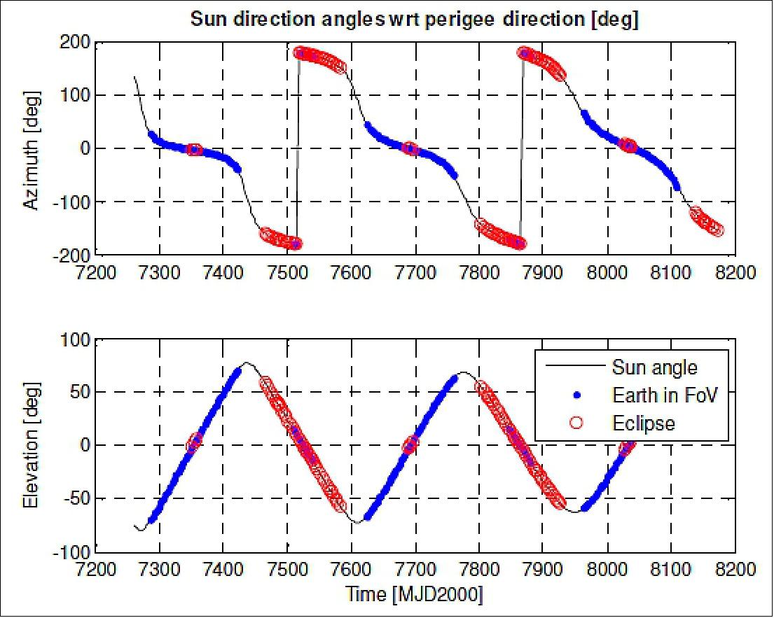
From Figure 64, it is therefore possible to determine the admissible dates for Part A+B1 and for Part B2, where for the latter part the perigee must be Sun-illuminated and the Earth shall be outside VBS FoV as well.
Sequence of Maneuvers: Part A+B1 requested maneuvers are implemented in three orbits of the PROBA-3 mission, as illustrated in Figure 65. The profile considers the sequence of operations for the first orbit described by the following:
• Cycle of maneuvers representing far range RV.
• Handover from nominal mission control to RVX in WP0 before reaching orbit apogee. Start in cooperative mode to gradually build confidence in operational chain. Cooperative VBS until post-perigee (WP2).
• First maneuver is a cooperative far-range hop from WP0 to WP1.
• Cooperative far-range hop from WP1 to WP2, arriving at the latter one with a range sufficiently large to ensure the target size smaller than 1 pixel in camera image.
• Chaser is always within VBS FoV at WPs (Waypoints).
• By design, all the hops satisfy the Sun-aligned geometry between chaser and target when at WP, as well as the Sun off-pointing constraint.
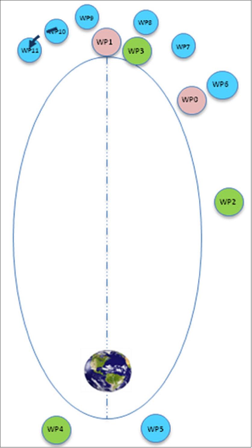
Operations for the second orbit begin once WP2 is reached. The following maneuvers are foreseen:
• Nominal range at WP2 guarantees the chaser to be of sub-pixel size as seen by VBS and the RVX experimental operations can start. Transition to non-cooperative mode occurs.
• After this point, a sequence of non-cooperative far-range hops are executed, being representative of RV maneuvers:
- Non-cooperative hop from WP2 to WP3. Transition from far-range to close-range RV.
- Non-cooperative hop from WP3 to WP4. Transition to cooperative mode for perigee passage in eclipse condition.
• At WP4 Sun-aligned station-keeping maneuver is performed until WP5, satisfying part B1 objective (forced motion at perigee during eclipse);
Operations for the third orbit begin once WP5 has been reached. The sequence of operations is the following:
• Transition to non-cooperative mode once perigee passage is over (WP5).
• Hop from WP5 to WP6.
• At WP6 the following set of forced maneuvers begin (Figure 66):
- Sun-aligned forced approach;
- Sun-aligned station-keeping;
- Inspection begins and ends in Sun-aligned condition, reaching a maximum inspection cone angle limited to meet non-cooperative VBS constraints. It is performed at constant range;
- Sun-aligned retreat.
• Perform handover from RVX to nominal mission control. Sun-aligned station-keeping maneuver is executed from the end of retreat motion until reaching the handover point defined after apogee.
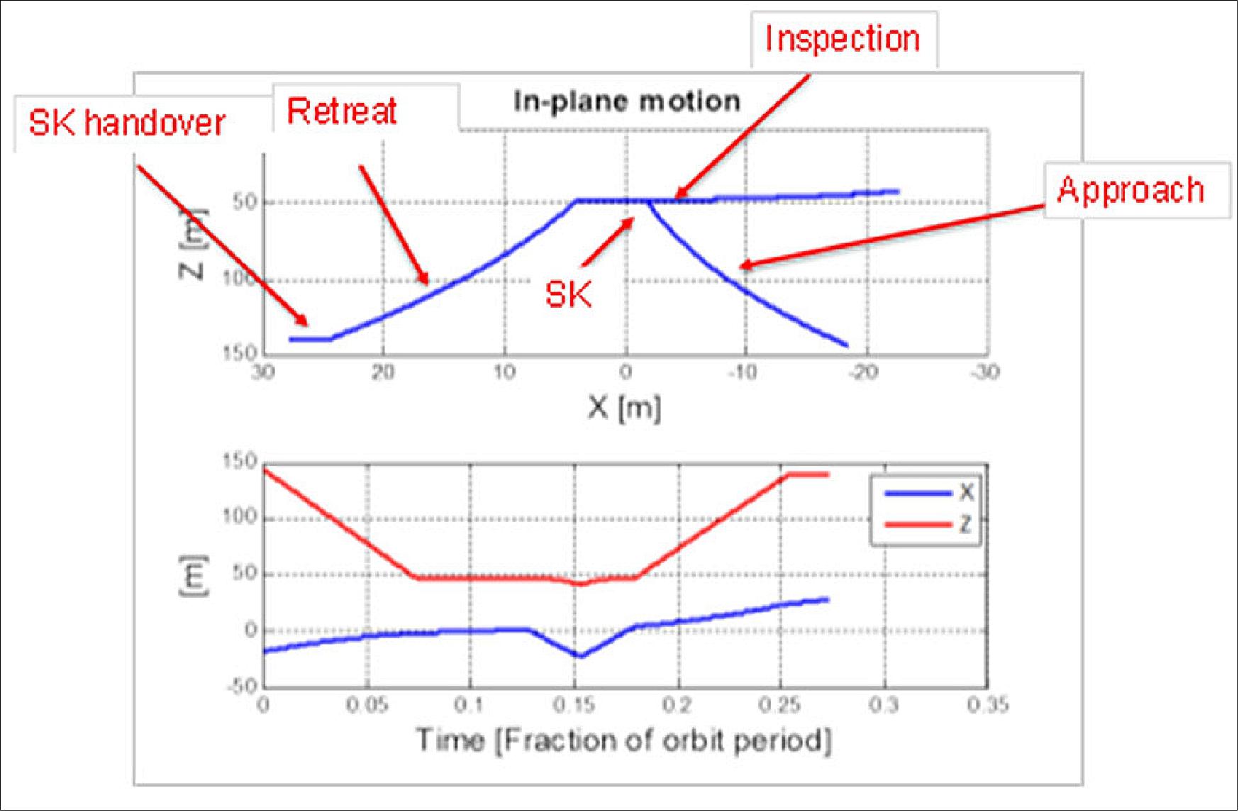
Part B2: Part B2 is implemented in two orbits, as illustrated in Figure 67. The first orbit comprises the maneuvers necessary to bring the S/C from handover to perigee itself; the second one comprises the perigee passage and maneuvers necessary to bring the S/C to the handover point at post-apogee.
Part B2 operations for the first orbit are described by:
• Handover from FF to RVX at WP0. Reaching WP1 through a forced motion retreat maneuver;
• Reaching pre-perigee WP2 by non-drifting hop;
• Demonstration of perigee passage under Sun illumination until WP3.
Part B2 operations for the second orbit are described by:
• Non-drifting hop from WP3 to WP4;
• Forced motion maneuver (i.e. retreat) towards handover distance;
• Station-keeping until reaching main mission control handover point.
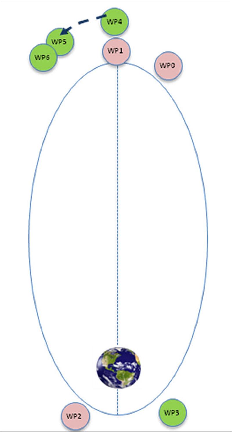
GNC (Guidance, Navigation and Control) Design and Analysis
The GNC functional chain is one of the key blocks of the P3RVX to ensure mission success. As such, it is designed to be able to cope both with nominal and failure scenarios, and is scheduled according to the mission phase. Therefore, a set of GNC modes has been devised, so that each mode is properly designed for the current operating conditions. Each of the elements of the GNC is analyzed in the following subsections.
Guidance: The higher-level objective of Guidance is to provide the appropriate references to ensure that the S/C follow the nominal trajectory profile for the RVX. For this purpose, Guidance receives inputs from Navigation and Mode Manager, and provides outputs to Control. In the case of hop maneuvers, the provided output is simply the desired boost direction and magnitude to be applied, while for forced motion maneuvers the outputs are the reference relative position and velocities.
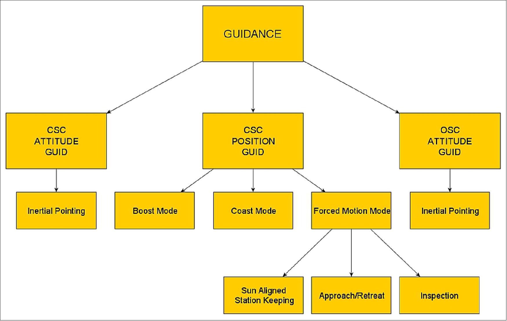
The Guidance function can be decomposed into the following functional elements, also shown in Figure 68:
• CSC/OSC Attitude Guidance: Computes the S/C attitude reference based on the sun direction and relative position inputs. Inertial attitude reference is provided to the controller, being possible to choose between target pointing or Sun pointing profiles.
• CSC Position Guidance: Provides the references that allow the CSC to follow the RVX reference trajectory profile. It is implemented into several modes:
- Boost Mode: Takes as input the current relative state of the chaser, as well as the definition of the desired hop maneuver given by the Mode Manager (target relative state and flight time), and computes the ΔV needed to reach the desired target state within the specified duration.
- Coast Mode: Provides no position control commands and instead only checks for hop maneuver completion and triggering of the next maneuver.
- Coast Mode: Provides no position control commands and instead only checks for hop maneuver completion and triggering of the next maneuver.
- Forced Motion Mode: Generates the reference position and velocity to be followed by the chaser.
With respect to the Forced Motion Mode, several different maneuvers can be implemented, as follows:
• SASK: Guidance will output a reference trajectory with a constant relative range and with a direction that ensures the S/C are Sun aligned. The range of the maneuver is given by the initial relative position of the S/C at the start of the SASK.
• Approach/Retreat: Starting from the initial range defined by the initial relative position at the start of the maneuver, Guidance generates a trajectory profile that brings the chaser to the desired final range, in the requested flight time, and maintaining the S/C Sun aligned.
• Inspection: Guidance commands a constant range circular arc, starting and finishing in Sun aligned direction. The arc is described within the orbital plane, while the cross-plane component is kept constant.
Navigation: The navigation function is responsible for generating estimates of the relative states – namely relative position, (linear) velocity, attitude, and angular velocity – of the S/C, in addition to (probabilistic or deterministic) bounds on the error of each estimate. In addition to that, and as a complementary capability, it may also be relevant to estimate certain parameters of the sensor suite, such as sensor bias.
The outputs from the navigation filter are, within the scope of RVX, mainly used by guidance, control, and FDIR. As a consequence, estimation errors in the navigation function may be propagated throughout the GNC functional chain and, thus, should be minimized, although having in mind the accuracy constraints that are imposed by the sensors.
The navigation approach adopted within the realm of RVX is based on the well-established Extended Kalman Filtering (EKF) theory, driven by the following four main design concerns:
• Accurate modelling of the state dynamics – the accurate modelling of the chaser’s relative motion and attitude kinematics is critical for state propagation. Accurate state prediction is necessary to keep the EKF linearized point valid, and to increase the system’s robustness to errors in aiding sensor readings. State prediction should also provide reliable estimates of the state whenever the G&C commands are applied.
• Integration of sensor information – the strategies for integrating the measurements from the available sensors (MIRU and VBS) must be carefully considered. The nonlinear model of the sensor reading must be correctly described as a function of the estimated state, and relevant sensor non-idealities, such as noise and bias, should be compensated for in the navigation system. In addition, within the scope of RVX, the VBS is mounted on the OSC, which, from the point-of-view of the experiment, is the target S/C. This unusual configuration dictated by the Sun vector (i.e. the sensor placed on the target instead of the chaser S/C) is circumvented by considering a virtual VBS mounted on the CSC, and whose measurements are computed based on those of the OSC VBS.
• Numerical stability and computational optimization – besides the analytic performance of the Kalman filter, the implementation of the navigation filter should account for computational issues. Namely, numerical methods should be adopted guaranteeing that the filter variables remain numerically-well defined, while the most appropriate state update techniques should be analyzed.
• Algorithmic updates motivated by sensor limitations – the navigation algorithm should be adapted to account for the image processing delay and of the GNC algorithm itself. The GNC algorithm should be designed such that G&C commands are applied at the proper time instant, irrespectively of the GNC processing delay. Also, a filtering strategy to integrate delayed measurement integration must be implemented, due to the delay between image capture and image processing.
Having these concerns in mind, the architecture depicted in Figure 69 was adopted, for design and implementation purposes, dividing the navigation problem into:
• Relative position and velocity
• Relative attitude estimation
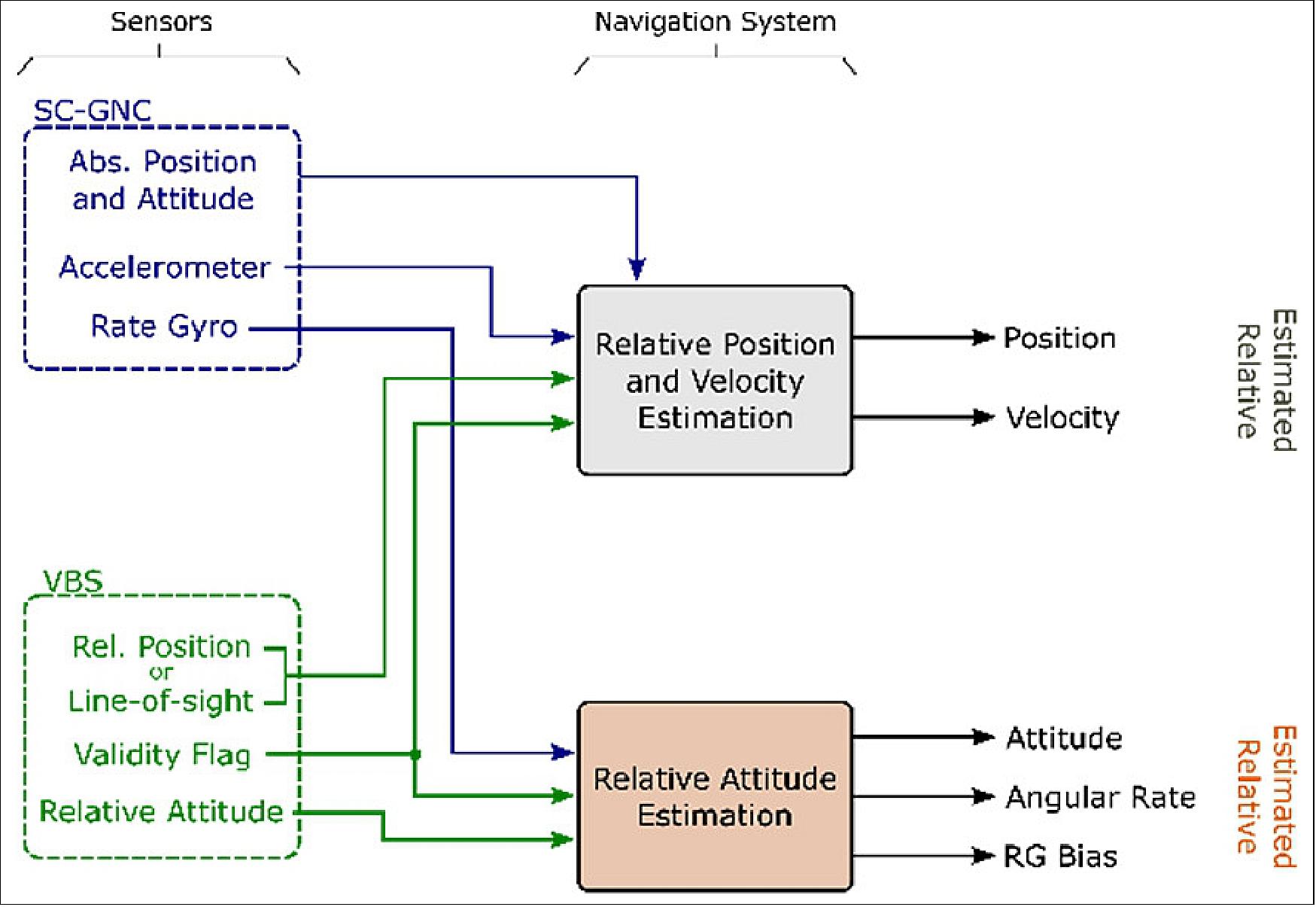
This functional modularity of the navigation filter increases its flexibility in terms of application and sensor suite selection, while also supporting the clear understanding of the underlying algorithms.
VBS (Vision-Based System): The objective of the VBS is to measure the relative state of the target spacecraft, which is the CSC, as seen from the VBS. The VBS measures the relative state by the means of optical sensors and highly advanced image processing techniques.
The VBS is based on the heritage of the micro Advanced Stellar Compass (µASC). The instrument has gained extensive flight heritage from the PRISMA (Prototype Research Instruments and Space Mission technology Advancement) mission of Sweden, where formation flight was successfully demonstrated covering both far- and close-range operations. When at close range, the VBS was only operated in cooperative mode. Therefore, the extended non-cooperative image processing module for close proximity operations is to be verified in-flight within the scope of RVX.
On-board OSC, the VBS system consists of a redundant Digital Processing Unit (DPU) that is connected to the redundant set of optical sensors. On the CSC segment the VBS consists of a redundant electrical unit that controls the redundant set of Mire units. An overview of the VBS components is shown in Figure 70. The functionality of each component is as follows:
• WAC (Wide Angle Camera) observing target with optimal performance from 12 -100 m range.
• NAC (Narrow Angle Camera) observing target with optimal performance from 50 - 550 m range.
• ISM (Integration Synchronization Module) registers the pulse from the Mire Beacons on CSC to synchronize the integration of the WAC and NAC with the pulsed Beacon.
• MOH (Mire Optical Head) emits a pulsed infrared signal. Combined, the MOHs enable 6 DOF resolution of the relative state when operating in cooperative mode.
• AMU (Acquisition Mire Unit) emits a high-power beacon that enables target acquisition at far range with Earth in the background of CSC.
• STR CHU (Star Tracker Camera Head Unit) observes the stellar sky to resolve the inertial pointing of the spacecraft.
• MIRU (Micro Inertial Reference Unit) is co-integrated with the STR CHU delivering angular rates at high bandwidth.
• DPU (Digital Processing Unit) that controls the optical sensor and processes the images. Determines the inertial pointing of the STR CHUs and the relative state of CSC using the VBS cameras.
The VBS system is integrated with the STR (Star Tracker) package: micro-Advanced Stellar Compass (µASC). This enables the VBS to output the relative state of the target spacecraft to be referenced in inertial coordinates.
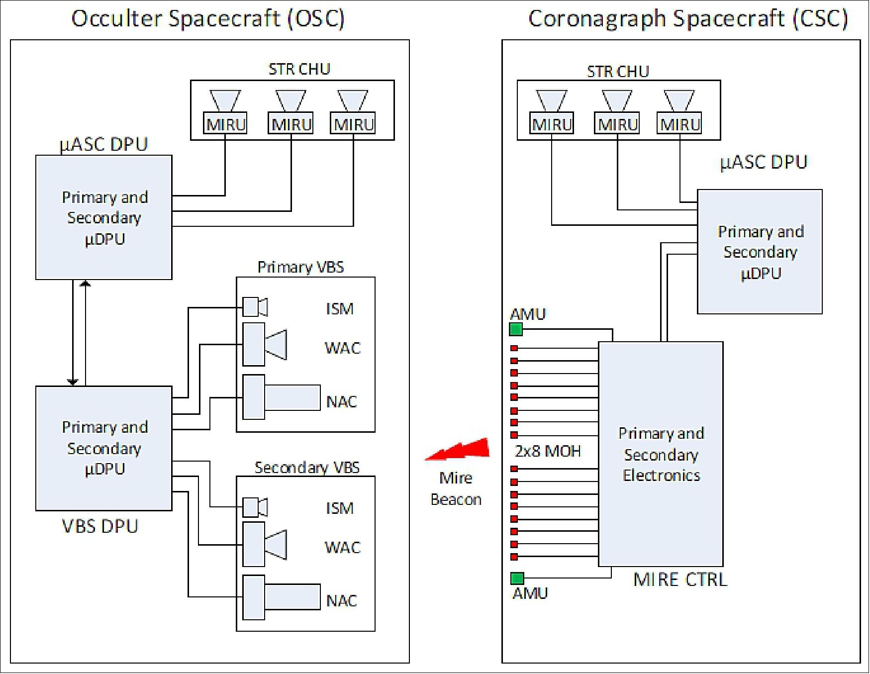
The VBS is capable of operating in either cooperative mode or non-cooperative mode:
• Cooperative Mode: The relative state is measured utilizing the active Mire Beacons on-board CSC and detected by the optical sensor on-board OSC. The MOHs and AMUs, mounted on the surface of the CSC, emit a Beacon that is detected by the ISM, WAC, and NAC onboard OSC. The MOHs are distributed in a specific pattern that is recognized by the VBS to resolve the relative state of OSC.
• Non-cooperative Mode: No information is actively transmitted between the two spacecraft. The VBS sensors will only register the Sun-lit surface of CSC, imposing the image processing to solve the relative state solely based on the external illumination of the target.
The VBS is able to resolve the full 6 DOF state of the target in both the cooperative and non-cooperative mode. However, the coverage of the solutions naturally depends on the actual range between the spacecraft:
• Far Range: the target spacecraft appears as a dot in the starry background. The VBS identifies the target amongst the stellar background and will resolve a Line of Sight (LOS) measure, 2 DOF.
• Close Range: As the range between the chaser and target reduces, the more resolved the target appears in the FOV of the VBS. In case of cooperative mode, the MOHs will be clearly detected and separated in the image allowing for either a 3DOF translational solution or a full 6 DOF pose/translation solution. Considering the non-cooperative mode with the Sun-lit target fully resolved in the image, the VBS recognizes the shape and contour of the spacecraft to resolve the 6 DOF pose/translation. This transition occurs at a range of ~100 m and ~550 m for the WAC and NAC, respectively.
Control: The main RVX Control function (RVXC) objectives are set to:
• Regulate the spacecraft translational and rotational states around the guidance reference;
• Compute commands for the spacecraft actuators, based on the processing of the control error;
In addition to the mentioned objectives, the 6DoF controller will have to be robust to:
• All significant sensor and actuator errors;
• CSC uncertainties;
• OSC uncertain/time varying orbital parameters;
To this end, an LTI MIMO (Linear Time-Invariant Multiple-Input Multiple-Output) controller is designed by solving an optimization problem aimed to ensure the CL robustness to complex-valued model uncertainty, as well as uncertain parameters.
The overall controller synthesis methodology can be structured into the following three steps:
Modelling: The derivation of a reliable model is of paramount importance for control design and analysis. The model adopted within the work reported in this document is obtained by using the so-called LFT (Linear Fractional Transformation) framework, which is particularly suitable for robust control design. The LFT framework allows the representation of the system to control by means of the feedback connection of the nominal plant G(s) and a block diagonal uncertainty Δ(s) gathering all the uncertain parameters of the system, as shown in Figure 71.
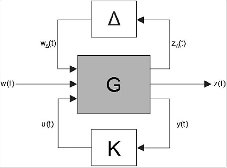
Controller design/synthesis: This step is where the controller is actually computed by using robust control design techniques. The controller synthesis problem (Figure 71) consists in finding the controller with transfer function K(s) that stabilizes the closed-loop system, while minimizing a given cost function. Specifically, two approaches to this problem are taken into consideration: H∞ unstructured control, and mixed-µ control synthesis. Both methods aim to obtain a controller which guarantees the robust stability of the closed-loop system in the presence of the uncertainties. However, while H∞ considers complex-valued unstructured uncertainties, the mixed-µ approach accounts both for complex and real-valued structured uncertainties. It thus results significantly more powerful in obtaining less conservative controllers. Nonetheless, the mixed-µ approach is computationally more demanding and more susceptible to numerical problems, issues which may hinder the synthesis of the controller.
Analysis: The closed-loop system with the controller obtained in the previous step is finally evaluated. For the closed loop analysis, µ-analysis techniques which permit to assess the robust stability of the system in presence of dynamical and parametric uncertainties are employed.
FDIR (Failure Detection, Isolation and Recovery) Design and Analysis
The RVX (Recovery Experiment) aims to be executed in an autonomous manner (i.e. without the need for Ground intervention), taking advantage of a FDIR (Fault Detection, Isolation, and Recovery) system to ensure continuous monitoring of the RVX GNC and the satellites’ relative state, and prompt response to failures, thus substantially reducing the probability that a failure leads to a safety critical scenario, and ultimately avoiding collision.
The aim of the RVX FDIR system is not to duplicate the functions of the System FDIR, but to identify potentially dangerous failures that may occur in the RVX GNC or non-cooperative VBS/IP (Vision Based Sensor/Internet Protocol) and provoke recovery actions by alarms to System FDIR.
The RVX FDIR is designed to ensure that the overall RVX SW is single-failure tolerant, i.e. that no single failure can jeopardize the mission, and ultimately the S/C. Two hypotheses are being considered by the FDIR system, based on the risk of collision:
• Imminent risk of collision: the FDIR system triggers a CAM (Collision Avoidance Maneuver), aiming to place the S/C in a drifting orbit (which ensures no collision can occur within a given period of time considered sufficient for the Ground to regain control of the mission);
• No risk of collision in short term, but the FDIR system detects unrecoverable failures that may end the mission without Ground intervention: the GSM (Go-to-Safe Maneuver) is triggered, which leads to the RVX being terminated and the control transferred to System FDIR actions. In both cases, the Ground intervention is required for the RVX to be resumed.
The aforementioned orbital reconfigurations involve losing formation and propellant consumption both for breaking the formation and for recovering it. Therefore, these actions are considered a last resource.
The RVX FDIR is autonomously performed by each satellite. The FDIR levels of the FF mission are adopted by the RVX. Following a similar strategy to the FF counterpart, the RVX FDIR is directly responsible only for L0 actions. For L1 to L4 actions, the RVX FDIR requests recovery actions to the System FDIR, with the latter being responsible for commanding or inhibiting these recovery actions. The recovery action is, in most cases, activating a contingency RVX mode. The L0-L4 actions are detailed the Figure 72.

The general design concept of the FDIR algorithms is governed by the presence of two levels of activities:
• Autonomously performed by the satellite (for identification and recovery): the FDIR considers all envisaged failures that may affect the safety of the RVX mission and all the SW failures of the RVX GNC.
• Performed under Ground Segment control (for identification and recovery). When an L3-L4 maneuver is commanded and the corresponding Δv is passed to the RVX SW, the Ground Station is the only entity able to resume the mission.
The RVX FDIR is programmable and parameterizable by the Ground Station at any time during the mission, through the following parameters and checks: enable/disable any FDI Check, enable/disable any FDI programmed recovery action, such as reconfigurations or mode change and modify/tune FDI parameters and thresholds. All the decisions, detections, identifications, and recovery actions of any failure are kept in a log and the Ground operator is informed automatically after the event takes place (upon download of telemetry). The following telemetry information is being used: Reconfiguration flags with explicit information regarding the event, current configuration flags with the post-event status and failures reported through dedicated event packages.
The FDIR design is implemented as FDIR Models and verified in either standalone or integrated GNC/FDIR test environments. Figure 73 depicts a block diagram of the CSC’s FDIR system.
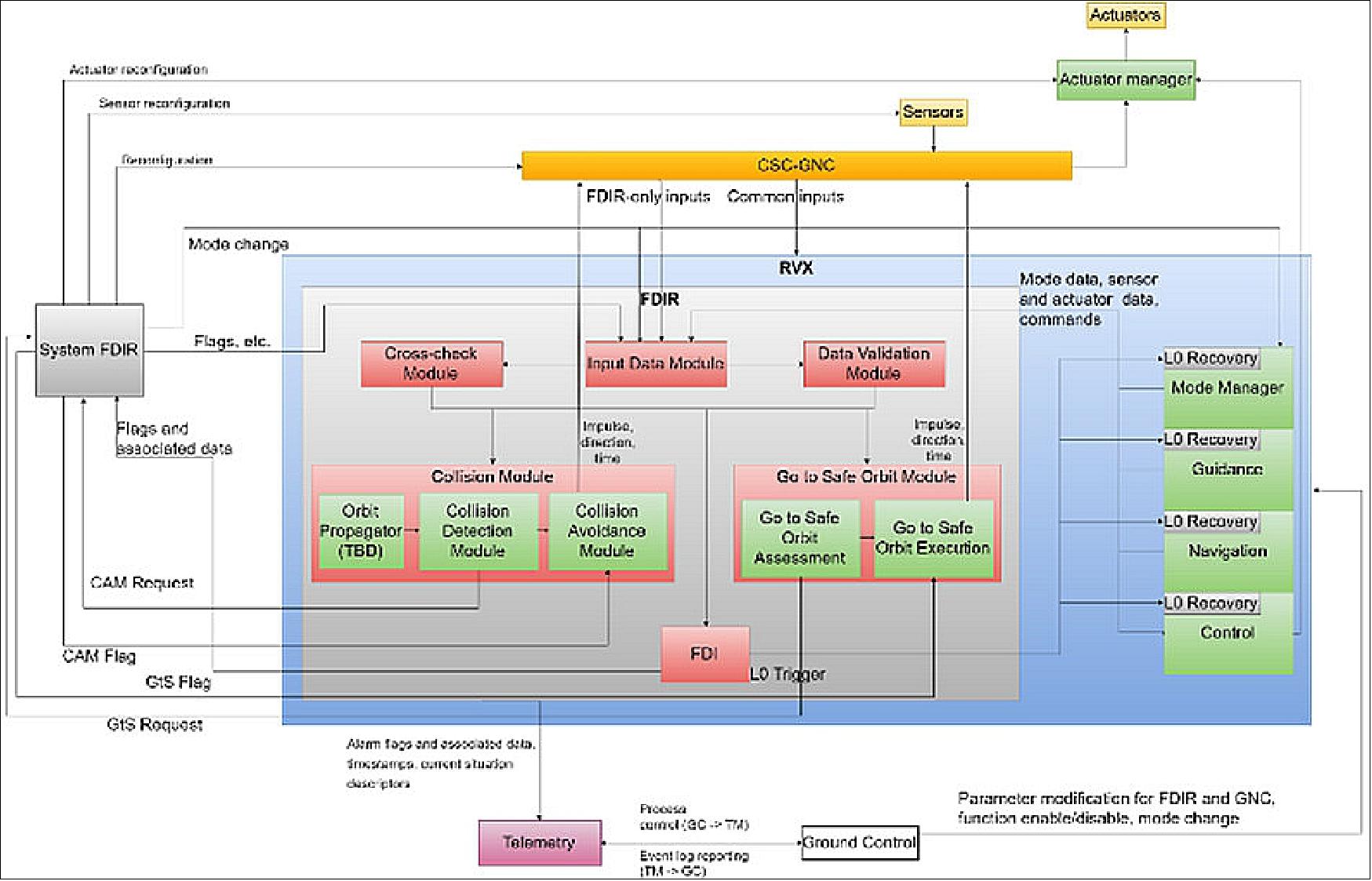
VBS FDIR: The VBS alike the STR is designed with a suite of in-line verification steps, aimed at eliminating false or erroneous signals from propagating up in the system. For example, the STR employs a set of morphological filters aimed at removing non-stellar objects, and only propagating star centroids with a reasonable shape to the ensuing search engine, the output of which is subsequently matched to all stars in the star catalogue, in a forward-backward match process eliminating false links. Finally, the matched centroid and star list error distribution is validated against expectations and outlier rejection performed. The result of the above is an extremely robust and accurate attitude stream, also during non-nominal conditions, virtually free of false positive solutions. Recovery from anomalies are automatic and optimized for robustness and speed, and include recovery from SEU/SEL radiation effects, power glitches, blinding or obscuration and vast optical overloads from non-stellar objects in the field of view.
The VBS share the same functionalities, and uses all of these in the case of cooperative tracking. In the case of non-cooperative tracking, and the far range common operations mode, the failure detections consist of a suite of illumination controls matching the image to expectations. The main disturbance source in nominal operations being short-lived glints from the target is handled by a special filter which attempts to recover optical information from the non-affected parts of the image and, if successful, direct the ensuing match engine to eliminate the affected parts of the image. If the glint is massive, the image will be suppressed from further processing. The ensuing match process is likewise equipped with a suite of filters, testing the match between the measured and the reference target model. Outlier filters like missing or suppressed objects and features are used to suppress false positive solutions.
This FDIR approach minimizing false positives to near zero, has as a consequence that a noticeable fraction of false negatives is emitted. This requires in turn that the GNC is tolerant to sporadic missing measurements, being false stamped pose-position solutions. This problem is tackled by the Navigation approach, which allows for the propagation of the state when no measurements are available, while updating the state only when they are available. This independence between the so-called predict and update cycles of the Navigation filter allows for a natural integration of measurements, while feeding Guidance and Control with periodic state estimates at a fixed rate.
In summary, the P3RVX (PROBA-3 RendezVous eXperiment) aims to consolidate RV technology, in particular with non-cooperative targets, with two satellites, in a highly elliptical orbit, using optical Navigation. The P3RVX will perform in-orbit demonstrations of the GNC (Guidance, Navigation, and Control) subsystem [including the FDIR (Fault Detection, Isolation, and Recovery) functions], the operations, the autonomy approach, and the VV (Verification and Validation), for missions in highly-elliptical orbits with fast and time-varying dynamics.
A series of close-proximity operations are considered, including non-cooperative rendezvous and forced-motion (inspection, approach/retreat, and station-keeping) maneuvers during perigee, with the latter being performed both in eclipse and in Sun-illuminated conditions.
The outcomes of P3RVX are aligned with ESA technology lines and, as such, are expected to have a significant impact on the community. In particular, the technologies being developed are of paramount importance for the support of short- and medium-term Clean Space and ADR (Active Debris Removal) lines, as well as the development of SSVs (Space Service Vehicles), also referred to as in-orbit servicing vehicles.
Ground Segment
The PROBA-3 ground segment is built upon the heritage from PROBA-1, PROBA-2 and PROBA-V, with high degree of reuse of processes, methods and modules. The Mission Operation Center is located at Redu (in Belgium) and the Ground Station is located at Santa-Maria in the Azores (in Portugal).
References
1) “Proba-3: ESA's first step towards formation flying,” Aug. 8, 2006, URL: http://www.esa.int/SPECIALS/Proba_web_site/SEM6I6JZBQE_0.html
2) T. Sephton, A. Wishar t, K. Strauch, F. Teston, “EO Formation Flying Applications for Small Satellite Missions,” Proceedings of the 6th IAA Symposium on Small Satellites for Earth Observation, Berlin, Germany, April 23 - 26, 2007
3) L .F. Peñín, J. C. Bastante, J. L. Cano, “Formation Flying Mission Analysis for PROBA-3,” 58th IAC (International Astronautical Congress), International Space Expo, Hyderabad, India, Sept. 24-28, 2007, IAC-07-C1.7.02
4) A. Wishart, F. Teston, S. Kemble, S. Grocott, A. Davies, C. Warren, K. Geelen, “The PROBA-3 Formation Flying Technology Demonstration Mission,” 58th IAC (International Astronautical Congress), International Space Expo, Hyderabad, India, Sept. 24-28, 2007, IAC-07-C1.7.01
5) “PROBA-3 Phase A Study Executive Summary Report,” EADS Astrium, Dec. 2007, URL: http://esamultimedia.esa.int/docs/gsp/completed/C20014ExS.pdf
6) F. Sjöberg, A. Karlsson, B. Jakobsson, “PROBA-3: A Formation Flying Demonstration Mission on the Verge to be Realized,” Proceedings of the 3rd International Symposium on Formation Flying, Missions and Technology, ESA/ESTEC, Noordwijk, The Netherlands, April 23-25, 2008, ESA SP-654, June 2008
7) T. V. Peters, L. Tarabini-Castellani, C. de Negueruela, S. Llorente, B. Jakobsson, “PROBA-3 Formation Flying Mission Analysis,” Proceedings of the 3rd International Symposium on Formation Flying, Missions and Technology, ESA/ESTEC, Noordwijk, The Netherlands, April 23-25, 2008, ESA SP-654, June 2008
8) Fredrik Sjöberg, Cristina de Negueruela, Björn Jakobsson, Anders Karlsson, B. Larsson, C. Carrascosa, Salvador Llorente-Martinez, Frederic Teston, Franz Burger, “High Precision Formation Flying Guidance, Navigation and Control for the PROBA-3 Mission,” Proceedings of the 59th IAC (International Astronautical Congress), Glasgow, Scotland, UK, Sept. 29 to Oct. 3, 2008, IAC-08.B4.2.5
9) PROBA-3 3rd Participants Meeting, March 13, 2008, URL: http://www.ffg.at/getdownload.php?id=2490
10) “Proba-3 mission,” May 20, 2009, URL: http://www.esa.int/esaMI/Proba/SEMQPC0OWUF_0.html
11) Agnès Mestreau-Garreau, Kristof Gantois, Alexander Cropp, David Evans, Frederic Teston, “PROBA 3: In-Orbit Demonstration Mission for High Precision Formation Flying,” Proceedings of the Symposium on Small Satellite Systems and Services (4S), Funchal, Madeira, Portugal, May 31-June 4, 2010
12) J. Salvador Llorente, Felix De Wispelaere, Felix, Francisco Javier Benito, Diego Escorial, Thomas Laroche , Agnes Mestreau-Garreau, “PROBA-3 System: In Flight Precise Formation Flying Technology Demonstration,” Proceedings of the 4S (Small Satellites Systems and Services) Symposium, Portoroz, Slovenia, June 4-8, 2012
13) L. Tarabini Castellani, S. Llorente, J.M. Fernandez, M. Ruiz, A. Mestreau-Garreau, A. Cropp, A. Santovincenzo, “PROBA-3 Mission,” Proceedings of the 5th International Conference on Spacecraft Formation Flying Missions and Technologies (SFFMT 2013), Munich, Germany, May 29-31, 2013, URL of paper: http://www.sffmt2013.org/PPAbstract/4111.pdf; URL of presentation: http://www.sffmt2013.org/PPAbstract/4111pr.pdf
14) J. S. Llorente, A. Agenjo, C. Carrascosa, C. de Negueruela, A. Mestreau-Garreau , A. Cropp, A. Santovincenzo, “PROBA-3:Precise formation flying demonstration mission,” Acta Astronautica Vol. 82, Issue 1, pp. 38-46, 2013
15) Andrei Zhukov, ”The PROBA-3 Mission and Its Contribution to Space Weather Studies,” Proceedings of HELCATS (Heliospheric Cataloguing, Analysis & Techniques Service), First Annual Open Workshop, Göttingen, Germany, May 19-22, 2015, URL: http://www.affects-fp7.eu/helcats-meeting/data/workshop_presentations/
20150522_1040_s5_The%20PROBA-3%20mission%20and%20its%20
contribution%20to%20space%20weather%20studies_azhukov.pdf
16) ”PROBA-3: set the controls for the verge of the Sun,” ESA, Sept. 12, 2016, URL: http://m.esa.int/Our_Activities/Space_Engineering_Technology/
Proba_Missions/Proba-3_set_the_controls_for_the_verge_of_the_Sun
17) Luis F. Peñin, Yann Scoarnec, J.M. Fernández-Ibarz, Carolina Cazorla, José Ramón Villa, Ronald Kassel, Francisco Javier Benito, Dominique Baudoux, Luigi Strippoli, Damien Galano, Karim Mellab, ”Proba-3: ESA’s small satellites precise formation flying mission to study the Sun’s inner corona as never before,” Proceedings of the 34rd Annual AIAA/USU Virtual Conference on Small Satellites, August 1-6, 2020, Logan, UT, USA, paper: SSC20-I-02, URL: https://digitalcommons.usu.edu
/cgi/viewcontent.cgi?article=4707&context=smallsat
18) J. Côté, A. St-Amour, B. Paijmans, A. Kron, J.-L. Beaupellet, J. de Lafontaine, “Attitude and Orbit Control Software: Recent Innovations for Upcoming Missions,” Proceedings of ASTRO 2010, 15th CASI (Canadian Aeronautics and Space Institute) Conference, Toronto, Canada, May 4-6, 2010
19) R. Sánchez-Maestro, A. Agenjo, L. Tarabini, A. Cropp, “PROBA-3 High Precision Formation Flying Control System,” Proceedings of the GNC 2011, 8th International ESA Conference on Guidance, Navigation & Control Systems, Carlsbad (Karlovy Vary), Czech Republic, June 5-10, 2011
20) Thomas V. Peters, João Branco, Diego Escorial, Lorenzo Tarabini Castellani, Alex Cropp, “Mission analysis for PROBA-3 nominal operations,” Proceedings of the 7th International Workshop on Satellite Constellation and Formation Flying (IWSCFF-2013), Lisbon, Portugal, March 13-15, 2013, paper: IWSCFF-2013-07-06, URL: http://openconf.iwscff.astrodynamics.org.pt/modulez/
request.php?module=oc_program&action=view.php&a=&id=31&type=2
21) “About PROBA-3, ESA, Nov. 19, 2012, URL: http://www.esa.int/Our_Activities/Technology/Proba_Missions/About_Proba-3
22) L. Tarabini Castellani, G. Rodriguez, S. Llorente, J.M. Fernandez, M. Ruiz, A. Mestreau, A. Cropp, A. Santovincenzo, “PROBA-3 Formation Flying Mission,” Proceedings of the 7th International Workshop on Satellite Constellation and Formation Flying (IWSCFF-2013), Lisbon, Portugal, March 13-15, 2013, paper: IWSCFF-2013-08-07, URL of abstract: http://www.sffmt2013.org/PPAbstract/4111.pdf
23) S. Roose, Y. Stockman, Z. Sodnik, “A lateral sensor for the alignment of two formation-flying satellites,” Proceedings of the 5th International Conference on Spacecraft Formation Flying Missions and Technologies (SFFMT), Munich, Germany, May 29-31, 2013, URL of paper: http://www.sffmt2013.org/PPAbstract/4026p.pdf , URL of presentation: http://www.sffmt2013.org/PPAbstract/4026pr.pdf
24) M. J. Bradshaw, Y. Gao, K. P. Homewood, L. Gagnon, S. Gagnon, ”Fine Lateral and Longitudinal Sensor (FLLS) on-board ESA’S PROBA-3 Mission,” Proceedings of the 68th IAC (International Astronautical Congress), Adelaide, Australia, 25-29 Sept. 2017, paper: IAC-17-A7-2.3
25) ”PROBA-3 formation-flying,” ESA, 6 May, 2013, URL: http://m.esa.int/spaceinimages/Images/2011/04/Proba-3_formation-flying
26) Luigi Gallo, Casey Lambert, Alex Koujelev, Stephane Gagnon, Martin Guibert, ”The Canadian Astro-H Metrology System,” Proceedings of SPIE, Vol. 9144,'Space Telescopes and Instrumentation 2014: Ultraviolet to Gamma Ray, 914456, July 24, 2014, doi:10.1117/12.2054921, Montreal, Canada
27) X. Barcons, K. Nandra, D. Barret, J.-W. den Herder, A. C. Fabian, L. Piro, M. G. Watson, and the Athena team, ”Athena: the X-ray observatory to study the hot and energetic Universe,” 10th International LISA Symposium (LISAX), Journal of Physics: Conference Series Vol. 610 (2015) 012008, doi:10.1088/1742-6596/610/1/012008, URL: http://iopscience.iop.org
/article/10.1088/1742-6596/610/1/012008/pdf
28) Pedro Rodrigues, Ricardo Mendes, Pedro Sinogas, André Oliveira, Karim Mellab, ”Enabling Inter-Satellite Link platform for multi-satellite missions,” Proceedings of the 66th International Astronautical Congress (IAC 2015), Jerusalem, Israel, Oct.12-16, 2015, paper: IAC-15-B2.5.7
29) ”Models of PROBA-3 designs,” ESA, May 4, 2016, URL: http://www.esa.int/spaceinimages/Images/2016/05/Models_of_Proba-3_designs
30) ”The Proba-3 program takes an important step in the integration of its two satellites,” Sener, 18 January, 2022, URL: https://www.aeroespacial.sener/en/press-releases/
the-proba-3-program-takes-an-important-step-in-the-integration-of-its-two-satellites
31) ”Corridor test of Proba-3’s formation flying sensors,” ESA Enabling & Support, 29 March 2021, URL: https://www.esa.int/Enabling_Support/Space_Engineering_Technology/
Proba_Missions/Corridor_test_of_Proba-3_s_formation_flying_sensors
32) ”SENER Aeroespacial and CATEC develop a 3D-printed metal antenna for the European Space Agency's PROBA-3 space mission,” SENER, 8 October 2019, URL: http://www.aerospace.sener
/press-releases/sener-aeroespacial-and-catec-develop-a-3d-printed
-metal-antenna-for-the-european-space-agencys-proba-3-space-mission
33) ”Antenna for PROBA-3,” ESA, 8 May 2019, URL: http://www.esa.int/spaceinimages/Images/2019/05/Antenna_for_Proba-3
34) Luigi Strippoli, Juan Antonio Bejar Romero, Marco Canetri, Julien Peyrard, Joao Branco, Thomas Vincent Peters, Ambroise Bidaux Sokolowsky, Pawel Miroslaw Brzoski, Jean-François Hamel, Pamela Woo, Marie-Kiki Langelier, Ludwik Sobiesak, Daniel Serrano, Rafael Contreras, Damien Galano, ”Proba-3 Formation Flying System, a key technology for future formation flying science missions: current status and simulation results,” Proceedings of the 69th IAC (International Astronautical Congress) Bremen, Germany, 1-5 October 2018, paper: IAC-18, A7.3.2, URL: https://iafastro.directory/
iac/proceedings/IAC-18/IAC-18/A7/3/manuscripts/IAC-18,A7,3,2,x47061.pdf
35) ”Science backing for formation-flying Sun-watcher Proba-3,” ESA, 17 July 2017, URL: http://www.esa.int/Our_Activities/Space_Engineering_Technology/
Proba_Missions/Science_backing_for_formation-flying_Sun-watcher_Proba-3
36) J. S. Llorente, A. Agenjo, C. Carrascosa, C. de Negueruela, A. Mestreau-Garreau, A. Cropp, A. Santovincenzo, “PROBA-3: Precise formation flying demonstration mission,” Acta Astronautica, 2012
37) T. V. Peters, J. Peyrard, C. Carrascosa, D. Escorial Olmos, “Detailed design of the PROBA-3 formation flying guidance,” Proceedings of IAC 2011 (62nd International Astronautical Congress), Cape Town, South Africa, Oct. 3-7, 2011, paper: IAC-11-C1.7.6
38) R. Sánchez-Maestro, A. Agenjo-Díaz, A. Cropp, “PROBA-3 Formation Flying High Performance Control,” Proceedings of the 5th International Conference on Spacecraft Formation Flying Missions and Technologies (SFFMT 2013), Munich, Germany, May 29-31, 2013, URL of paper: http://www.sffmt2013.org/PPAbstract/4090p.pdf, URL of presentation: http://www.sffmt2013.org/PPAbstract/4090pr.pdf
39) “Simulating the formation-flying future of space,” ESA, Sept. 9, 2010, URL: http://www.esa.int/esaCP/SEMQ71HONDG_index_0.html
40) João Branco, Diego Escorial, Valentin Barrena, “The Design of the Formation Flying Navigation for PROBA-3,” Proceedings of the 5th International Conference on Spacecraft Formation Flying Missions and Technologies (SFFMT), Munich, Germany, May 29-31, 2013, URL: http://www.sffmt2013.org/PPAbstract/4067p.pdf
41) Julien Peyrard, Diego Escorial, Alfredo Agenjo, Aymeric Kron, Alexander Cropp, “Design and Prototyping of PROBA-3 Formation Flying Sytem,” Proceedings of the 5th International Conference on Spacecraft Formation Flying Missions and Technologies (SFFMT), Munich, Germany, May 29-31, 2013, URL of paper: http://www.sffmt2013.org/PPAbstract/4069p.pdf , URL of presentation: http://www.sffmt2013.org/PPAbstract/4056pr.pdf
42) Etienne Renotte, Elena Carmen Baston, Alessandro Bemporad, Gerardo Capobianco, Ileana Cernica, Radoslav Darakchiev, François Denis, Richard Desselle, Lieve de Vos, Silvano Fineschi, Mauro Focardi, Tomasz Górski, Rafał Graczyk, Jean-Philippe Halain, Aline Hermans, Carl Jackson, Christian Kintziger, Jacek Kosiec, Nektarios Kranitis, Federico Landini, Vít Lédl, Giuseppe Massone, Alexandra Mazzoli, Radek Melich, Dominique Mollet, Michał Mosdorf, Gianalfredo Nicolini, Bogdan Nicula, Piotr Oleański, Marie-Catherine Palau, Maurizio Pancrazzi, Antonis Paschalis, Radek Peresty, Jean-Yves Plesseria, Miroslaw Rataj, Marco Romoli, Cédric Thizy, Michel Thomé, Kanaris Tsinganos, Ryszard Wodnicki, Tomasz Walczak, Andrei Zhukov, ”ASPIICS: an externally occulted coronagraph for PROBA-3.Design evolution,” Proceedings of SPIE, Vol. 9143, 'Space Telescopes and Instrumentation 2014: Optical, Infrared, and Millimeter Wave,' URL: https://orbi.uliege.be/bitstream/2268/200514/1/SPIE_9143_87_Renotte.pdf
43) Luis F. Peñín, Jose M. Fernández-Ibarz, Yann Scoarnec, Victor Marco, Diego Rodríguez, Agnes Mestreau-Garreau, Damien Galano and Karim Mellab, ”Proba-3 Mission: Creating an artificial solar eclipse every day by spacecraft flying in formation,” Proceedings of the 69th IAC (International Astronautical Congress) Bremen, Germany, 1-5 October 2018, paper: IAC-18.D1.2.1, URL: https://iafastro.directory
/iac/proceedings/IAC-18/IAC-18/D1/2/manuscripts/IAC-18,D1,2,1,x44885.pdf
44) P. L. Lamy, S. Vivès, W. Curdt, L. Damé, J. Davila, J.-M. Defise, S. Fineschi, P. Heinzel, R. Howard, S. Kuzin, W. Schmutz, K. Tsinganos, A. Zhukov, “ASPIICS: A Giant, White Light and Emission Line Coronagraph for the ESA PROBA-3 Formation FlighT Mission,” ICSO 2010 (International Conference on Space Optics), Rhodes Island, Greece, Oct. 4-8, 2010, URL: http://congrex.nl/ICSO
/Papers/Session%204b/FCXNL-10A02-1987610-1-LAMY_ICSO_PAPER.pdf
45) F. Stathopoulos, S. Vives, L. Damé, K. Tsinganos, “Mathematical Modelling of the complete Metrology of the PROBA-3/ASPIICS Formation Flying Solar Coronagraph,” ICSO 2010 (International Conference on Space Optics), Rhodes Island, Greece, Oct. 4-8, 2010, URL: http://congrex.nl/ICSO/
Papers/Session%2013b/FCXNL-10A02-2018080-1-STATHOPOULOS_ICSO_PAPER.pdf
46) J.-Y. Plesseria, P. Levacher, W. Curdt, S. Vives, C. Guillon, A. Mazzoli, F. Rouesnel, A. Paschalis, N. Kranitis, A. Poulakidas, B. Fiethe, S. Shestov, S. Gunar, G. Capobianco, P. Lamy, P. Rochus, K. Tsinganos, S. Kuzin, P. Heinzel, S. Fineschi, and the ASPIICS team. “Design and Development of ASPIICS, an Externally Occulted Solar Coronagraph for PROBA-3 Mission,” Proceedings of the 5th International Conference on Spacecraft Formation Flying Missions and Technologies (SFFMT), Munich, Germany, May 29-31, 2013, URL: http://www.sffmt2013.org/PPAbstract/4089p.pdf
47) S. Vives, A. Mazzoli, F. Landini, R. Melich, C. Escolle, J.-Y. Plesseria, C. Guillon, P. Levacher, “Optical Performance of the PROBA-3/ASPIICS Solar Coronagraph,” Proceedings of the 5th International Conference on Spacecraft Formation Flying Missions and Technologies (SFFMT), Munich, Germany, May 29-31, 2013, URL: http://www.sffmt2013.org/PPAbstract/4050p.pdf
48) S. Vivès, P. Lamy, P. Levacher, J. L. Boit, M. Saisse, “ Formation flying applied to solar coronal diagnostics: the ASPIICS coronagraph", Proceedings of SPIE, Vol. 6265, 'Space Telescopes and Instrumentation I: Optical, Infrared, and Millimeter Wave,' Orlando, FL. USA, June 14, 2006; doi:10.1117/12.671621
49) P. Lamy, S. Vivès, “New Perspective in Solar Coronal Physics: Giant Externally-Occulted Coronagraphs using Satellites in Flight Formation,” 58th IAC (International Astronautical Congress), International Space Expo, Hyderabad, India, Sept. 24-28, 2007, IAC-07-A3.1.02; also available in Acta Astronautica ,Volume 65, Issues 1-2, July-August 2009, pp. 273-278
50) S. Viv`es, P. Lamy, S. Koutchmy, J. Arnaud, “ASPIICS, a giant externally occulted coronagraph for the PROBA-3 formation flyer mission,” 36th COSPAR Scientific Assembly, Beijing, China, July 16-23, 2006
51) P. Lamy, S. Vives, S. Koutchmy, J. Arnaud, “Scientific Objectives of the Novel Formation Flying Mission: ASPIICS,” http://www.uni-sw.gwdg.de/~bothmer/projects/aspiics/aspiics-soho17-2006-v1.pdf
52) F. Landini, A. Mazzoli, M. Venet, S. Vives, M. Romoli, P. Lamy, G. Massone, “ASPIICS/PROBA-3 Formation Flying Solar Coronagraph: Stray Light Analysis and Optimization of the Occulter,” ICSO 2010 (International Conference on Space Optics), Rhodes Island, Greece, Oct. 4-8, 2010, URL: http://congrex.nl/ICSO/Papers/Session%209a/FCXNL-10A02-1987947-1-LANDINI_ICSO_PAPER.pdf
53) Sebastian Vives, Philippe Lamy, P. Leyacher, M. Marcellin, S. Koutchmy, J. Arnaud, E. Quemerais, L. Dame, R. Lallement, J. C. Vial, R. Harrisson, N. R. Waltham, P. Rochus, J. M. Defise, D. Berghmans, J. F. Hochedez, J. Pacheco, J. Blanco, J. M. Rebordao, D. Maia, W. Schmutz, A. Benz, G. Naletto, “ASPIICS on PROBA-3,” Proceedings of SPIE, San Diego, August 26, 2007, URL: http://www.asu.cas.cz/_data/proba3_sandiego.ppt
54) M. Venet, C. Bazin, S. Koutchm2, P. Lamy, “Stray Light Rejection in Giant Externally-Occulted Solar Coronagraphs: Experimental Developments,” ICSO 2010 (International Conference on Space Optics), Rhodes Island, Greece, Oct. 4-8, 2010, URL: http://congrex.nl/ICSO/Papers
/Session%209b/FCXNL-10A02-1987633-1-VENET_ICSO_PAPER.pdf
55) A. Paschalis, N. Kranitis, G. Theodorou, A. Poulakidas, G. Haritakis, D. Habas, P. Levacher, W. Curdt, H. Michalik, B. Fiethe, K. Tsinganos, C. Gontikakis, J.-Y. Plesseria, and the ASPIICS team, “ASPIICS CCB: The Functional Control Electronics of an Externally Occulted Solar Coronagraph Instrument for the ESA PROBA-3 Mission,” Proceedings of the 5th International Conference on Spacecraft Formation Flying Missions and Technologies (SFFMT), Munich, Germany, May 29-31, 2013, URL: http://www.sffmt2013.org/PPAbstract/4100p.pdf
56) Paulo Rosa, Pedro Freire Silva, Baltazar Parreira, Miguel Hagenfeldt, Andrea Fabrizi, Antonio Pagano, Antonio Russo, Samuele Salvi, Murray Kerr, Silvana Radu, Anthonius Daoud-Moraru, Constantin Alexandru Pandele, Adrian-Mihail Stoica, Sergiu Stefan Mihai, Alessandro Massaro, David A. K. Pedersen, John Leif Jørgensen, Sergio Tiraplegui Riveras, Rafael Contreras, Alexander Cropp, Jonathan Grzymisch, ”Autonomous Close-Proximity Operations in Space: The PROBA-3 Rendezvous Experiment (P3RVX),” Proceedings of the 69th IAC (International Astronautical Congress) Bremen, Germany, 1-5 October 2018, paper: IAC-18-C1.5.10, URL: https://iafastro.directory/iac/
proceedings/IAC-18/IAC-18/C1/5/manuscripts/IAC-18,C1,5,10,x47313.pdf
The information compiled and edited in this article was provided by Herbert J. Kramer from his documentation of: ”Observation of the Earth and Its Environment: Survey of Missions and Sensors” (Springer Verlag) as well as many other sources after the publication of the 4th edition in 2002.
Spacecraft Development Status Launch Sensor Complement Ground Segment References
Back to top