QZSS (Quasi Zenith Satellite System)
Non-EO
JAXA
Quick facts
Overview
| Mission type | Non-EO |
| Agency | JAXA |
| Launch date | 11 Sep 2010 |
QZSS (Quasi Zenith Satellite System)
Spacecraft Launch Mission Status Sensor Complement Secondary Payload Ground Segment References
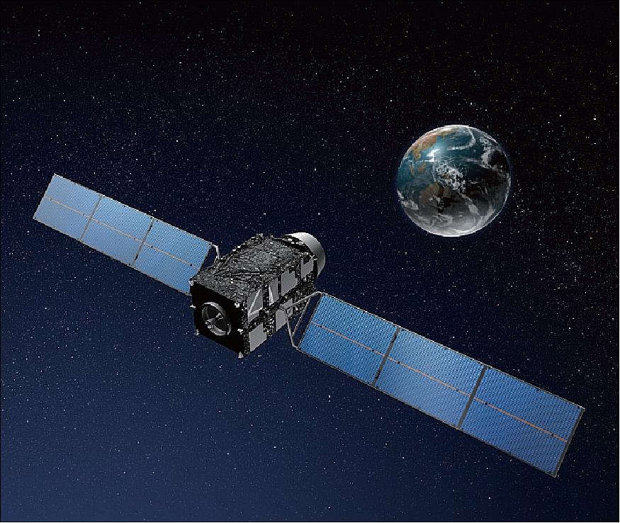
QZSS (nickname of Michibiki - meaning to 'guide' or 'show the way') is a Japanese regional satellite navigation system. The navigation system objective is to broadcast GPS-interoperable and augmentation signals as well as original Japanese (QZSS) signals from a three-spacecraft constellation in inclined, elliptical geosynchronous orbits. With this system concept, users in and around Japan and Oceania/Australia can use seamless positioning, navigation, and timing services, even in urban canyons and mountainous areas. 1) 2) 3) 4) 5) 6) 7) 8) 9) 10) 11) 12) 13) 14)
The design concept of QZSS differs greatly from those implementations of the GPS, GLONASS and Galileo systems because the requirements of the Japanese system are quite different in terms of service, service area, and, more importantly, the policy of national space development underlying them. The goal of QZSS is to provide a means of improved and secure navigational references to be used nationwide for many applications in all facets of modern life. A law to this effect was approved by the Japanese Diet in August 2007.
QZSS occupies a unique location within the spectrum of satellite navigation systems in that it is designed to augment another satellite navigation system (in this case, GPS) but is not limited to a "bent-pipe" transposition of ground-generated ranging signals through a GEO communications satellite. Instead, QZSS satellites will occupy inclined elliptical geosynchronous orbits for optimal high-elevation visibility in the area of coverage. The QZSS constellation (when completed) will operate more like independently-operating GPS or Galileo navigation satellites rather than in the restricted ground-controlled manner common to SBAS GEO augmentation satellites. 15)
This precedent is important for the future of GNSS (Global Navigation Satellite System) because, while only a very few nations or groupings of nations have the resources to build their own complete satellite navigation system on the scale of GPS, many other nations will have the capability to build GNSS augmentations on the scale of QZSS in the future, and the benefits that can be obtained for users in those nations are substantial compared to the much lower costs of QZSS-scale systems compared to GPS-scale systems.
Background:
In June 2002, a joint board was established between four Ministries of the Japanese Government: MEXT (Ministry of Education, Culture, Sports, Science and Technology), MPHPT (Ministry of Public Management, Home Affairs, Post and Communications), METI (Ministry of Economy, Trade and Industry) and MLIT (Ministry of Land, Infrastructure and Transport). The goal was to promote the QZSS program. QZSS was planned as a PPP (Public Private Partnership) program whose navigation payload was to be flown on the next-generation geostationary communication satellites of Japan.
• A conceptual study phase (Phase A) took place in 2003.
• The definition phase (Phase B) took place in 2004
• The design phase (Phase C) took place in 2005.
Originally, QZSS was jointly planned as a system for multiple missions of next-generation satellite communications and navigation services by the private sector and the Japanese government. Then in March 2006, the Japanese government announced the following principles for an R&D policy regarding QZSS:
• QZSS will be dedicated for spaceborne PNT (Positioning, Navigation, and Timing) services only (the complex multi-mission concept was deleted)
• A step-by-step R&D process was followed involving:
- Technological verifications and demonstrations by using initially only the first satellite, planned to be launched in late March 2010 (the end of JFY2009)
- After the evaluation of the results of technological verifications and demonstrations of the 1st stage, the 2nd and 3rd satellites will be built for system demonstration with industry participation.
• With the PNT experiment system design for the 1st stage completed (2008), flight H/W is being manufactured and tested.
• The CDR (Critical Design Review) for the spacecraft bus system took place on May 13, 2008.
Overall, JAXA was put in charge of designing and developing the new system concept - consisting initially of the first spacecraft and the corresponding ground segment. Technical demonstration, verification, and experiments for applications will be conducted by related national laboratories, ministries, the private sector (industry), and JAXA by broadcasting GPS-compatible and augmentation signals, as well as original Japanese messages using the first satellite (Ref. 1).
In January 2006, a GPS/QZSS interoperability agreement was signed between the USA and Japan to provide compatible signals for the user community.
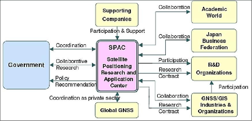
On Feb. 5, 2007, a new public-interest foundation SPAC (Satellite Positioning Research and Application Center) was established by the four Ministry (MEXT, MIC, METI and MLIT) approval to promote navigation satellite technology application and consequential geospatial information utilization (Figure 2). 16)
Agency/Institute, (Sponsor) | Function |
JAXA (Japan Aerospace Exploration Agency), (MEXT) | Development of satellite navigation technologies, integration of QZSS navigation system, and development of the first QZSS satellite and satellite control & tracking ground station. |
NICT (National Institute of Information and Communications Technology), (MLIT) | Development of timing control technologies |
ENRI (Electronic Navigation Research Institute), (MLIT) | Development of submeter class GPS Augmentation technologies with L1‐SAIF (Submeter‐class Augmentation with Integrity Function) signal |
GSI (Geographical Survey Institute), (MLIT) | Development of centimeter or decimeter class GPS Augmentation technologies with NW‐RTK |
AIST (National Institute of Advanced Industrial Science and Technology), (METI) | Development of precise onboard clock timing control technology |
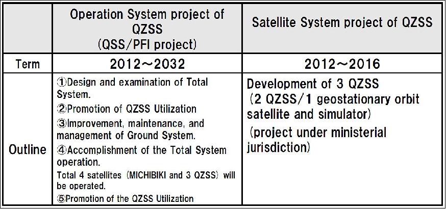
QZSS (Quasi-Zenith Satellite System) is a national undertaking, operated by the Cabinet Office of Japan. The program was divided into 2 divisions since the end of 2012 : Satellite System (project under ministerial jurisdiction), and Operation System (PFI). 17)
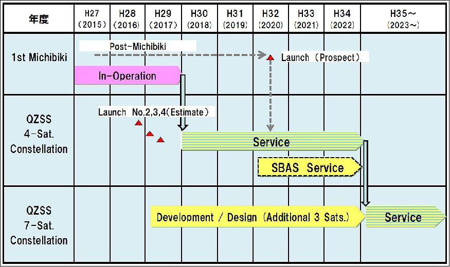
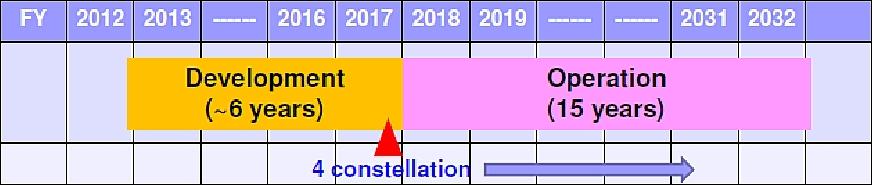
• Based on the decision of the Jepanese Government, the deployment of the operational QZSS is underway.
- A 4 satellite constellation shall be established by the 2018 JFY
- The required equipment (satellite, ground station and others) are currently in development
- The Japanese Government has decided to upgrade the QZSS to a 7-satellite constellation in the 2020's.
• Verification, assessment and many performance demonstrations of the QZSS have been conducted.
• The SBAS (Satellite Based Augmentation System) signal will be provided via QZSS.
- The SBAS service will be available from 2020's under the Ministry of Land, Infrastructure, Transport and Tourism jurisdiction.
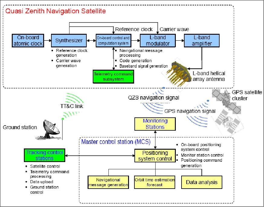
Elements of the QZSS System Architecture
The QZSS system consists of a space segment and a ground segment. The space segment consists initially of a single QZS (Quasi-Zenith Navigation Satellite). The ground segment mainly comprises a Master Control Station (MCS), a Monitoring Station (MS), Tracking and Control Stations (TCS), and systems of other national research institutes. About 10 MSC will be placed around Japan and overseas to estimate and predict the QZS orbit and clock more precisely (Figure 29). 18)
Orbit of the QZSS
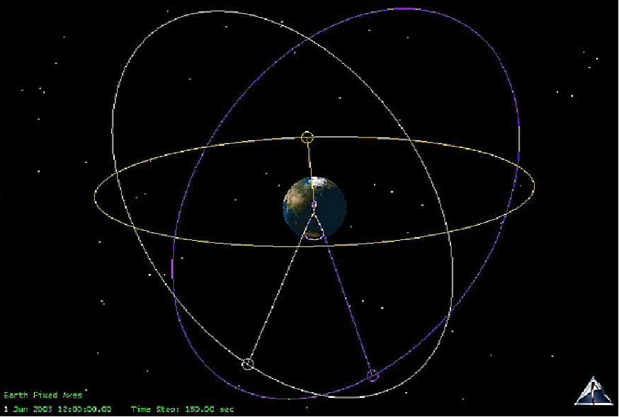
Semi-major axis = 42,164 km (±10 km), eccentricity = < 0.099, inclination = 39º ~ 47º, argument of perigee = 270º ± 1º, central longitudinal ground track = 135º ±5º East, period = 23 hours 56 minutes.
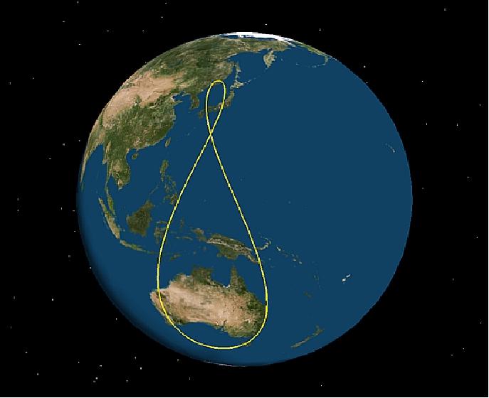
The QZSS constellation in the final operational stage consists of three satellites in inclined, elliptical geosynchronous orbits whose planes are 120º apart (Figure 5, ground track in Figure 6). 19) 20)
The QZSS constellation is regarded a next-generation augmentation system of GPS in the Asia/Pacific region. The main objectives of QZSS are GPS availability enhancement and GPS performance enhancement. In particular, the former is to utilize the QZS at high elevation angles in combination with GPS, to improve the GPS signal reception in urban canyons and in mountainous terrain.
In order to facilitate GPS availability enhancement, the navigation signals and messages of the QZSS have complete interoperability with those of GPS. Users can receive advanced positioning service combining GPS and QZSS without being aware of the difference between the two systems. GPS performance enhancement is achieved by transmitting high-accuracy position correction data along with integrity data via QZSS. Research organizations supervised by MLIT are undertaking research and development for these performance enhancement technologies.
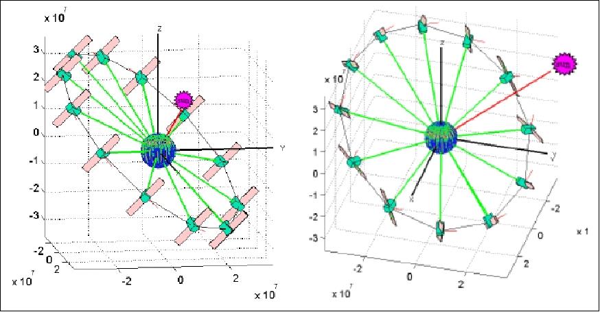
Due to the highly inclined orbit of the QZS-1, the β angle, which is the incidence angle of the solar light to the orbit plane of the satellite, can be over 60º during certain seasons. Maintaining an orbit-normal attitude with such a high β angle causes a greater electric power loss.
A yaw steering attitude control concept is one way to solve this problem with its steady power supply from the solar array, which will enable the stable and constant navigation mission operations even through the periods with a large β angle (Figure 7). The QZS-1 is equipped with the following systems in addition to the traditional geostationary satellite bus technology to support the successful operation:
• The attitude control system applicable for the yaw steering attitude maneuver
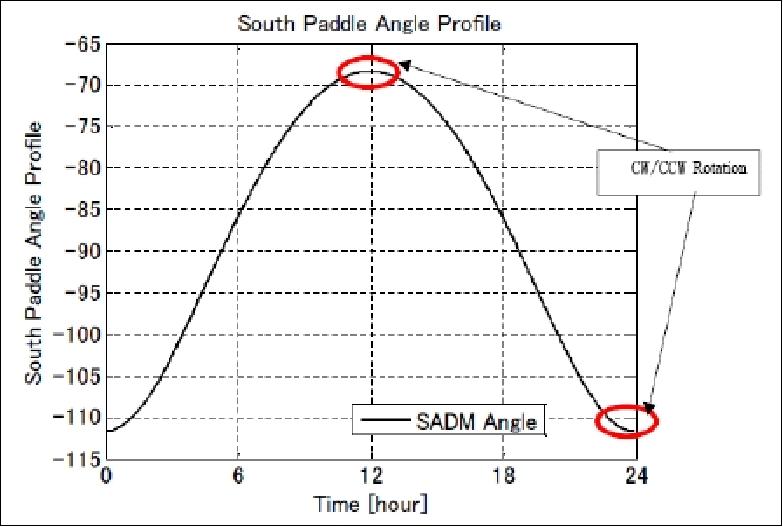
• The control system over the sinusoidal type curve drive of the solar array paddle.
Figure 8 shows the angle of solar array paddle while yaw steering. The paddle driving mechanical part is to be verified on its durability for the on-orbit operation period through a ground test with the simulated driving patterns.
Spacecraft
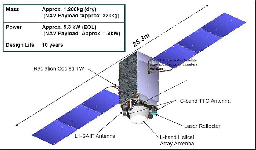
The QZS-1 bus design is of ETS-8 (Engineering Test Satellite-8) heritage - to favor a relatively short development period. ETS-VIII is in geostationary orbit with a launch Dec. 18, 2006. The bus has a dry mass of 1800 kg, a launch mass of 4100 kg, and a design life of > 10 years. The selection of the ETS-VIII bus is considered adequate and frugal since the QZSS constellation of three spacecraft is rather small as compared to the GPS and Galileo constellations. MELCO (Mitsubishi Electric Corporation) Kamakura Works, Kamakura-City, Japan is the prime contractor of the QZS-1 spacecraft. 21) 22) 23) 24) 25)
Some modifications to the bus are made to satisfy the special requirements derived from the navigation payloads and the unique orbit of QZS-1. Special attention is devoted to designing a robust satellite. Most main payloads are redundant.
The EPS (Electrical Power Subsystem) has dual bus power system for robustness. Key components are powered from two independent electrical bus systems. A Li-ion battery, provided by METI and NEDO (New Energy and Industrial Technology Development Organization), is used for eclipse operations. The power subsystem provides 5.3 kW (EOL). About 2 kW are needed for the operation on the navigation payload.
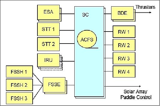
The AOCS (Attitude and Orbit Control Subsystem) is based on 3-axis stabilization (the S/C antenna must always point to Earth's center of mass). Using the well known yaw steering attitude maneuver, i.e. steering the spacecraft around its nadir axis, it is possible to maintain the solar array axis perpendicular to the sun axis. Actuation is provided by four RW (Reaction Wheels). The spacecraft attitude is sensed with fine sun sensors, Earth-scanning sensors, rate gyros, and star trackers (STT). The pointing accuracy is 0.1º.
The QZS-1 attitude and orbit control system has three key features to satisfy the requirements for antenna pointing and improve the mission availability. 26)
1) The QZS-1 takes the yaw steering attitude in some seasons to orient the solar array paddles normal to the sun for sufficient electrical power generation and to keep the satellite in a stable thermal condition because the orbit has an inclination of 43º nominal resulting in a wide beta angle range.
2) The QZS-1 features a robust design: the satellite can continue the mission even after one failure of any sensor, actuator or main computer.
3) To improve the service availability, the intervals of maneuvers for orbital control and reaction wheel momentum unloading must be maximized. The maneuvers degrade the orbital determination accuracy. They engender suspension of the navigation mission because we must redetermine and predict the orbit.
The AOCS configuration is shown in Figure 10, featuring two STT (Star Trackers), two redundant sets of three FSSH (Fine Sun Sensor Heads), and two redundant FSSE (Fine Sun Sensor Electronics), two ESA (Earth Sensor Assemblies), one internally redundant IRU (Inertial Referent Unit) and two redundant fault-tolerant onboard computers called the Satellite Controller (SC). The ACFS (Attitude and orbit Control Software) is installed in the SC.
QZS-1 uses an onboard orbit propagator. Combined with the attitude profile generator, the orbit propagator provides/maintains knowledge of the sun direction with respect to the spacecraft in the body frame. The orbit propagator also automatically generates the commands to the attitude control system and to the solar paddle drive electronics. The collected data of the Earth scanning sensor are being processed by the propagator and are used for attitude control if necessary. Ephemeris data are updated periodically using ground commands based on ranging results.
QZS-1 precise orbit ephemeris will be transmitted through the QZS-1 Navigation Message in the same way as GPS.
The thermal subsystem uses the passive control means of ETS-8 heritage. Heat pipe arrays installed inside the north and south panels are connected to maintain a stable heat radiation environment under the seasonally changing thermal input attributable to the direction of the sun. Some heat pipe channels are dedicated for use by the RAFSs (Rubidium Atomic Frequency Standard) clocks to satisfy precise temperature requirements (20ºC ± 5ºC) without being affected by the outer environment and other equipment. Attention is also devoted to providing a stable radio magnetic field to the RAFSs by arranging the component layout.
BPS (Bi-Propellant Subsystem): This subsystem enables the injection of the satellite onto the quasi zenith orbits after their separation from the launch vehicle, the orbit and attitude control through the 12-year mission, and the re-orbit. The re-orbit has to be processed so that it will not affect in any way on a satellite in the geostationary orbit in future.
RF communications: TT&C (Telemetry Tracking and Command) subsystem: S-band will be applied for the LEOP & contingency phases, and C-band will be applied for the routine phase operation (the C-band is used for avoidance of interference with other geostationary spacecraft). The uplink is designed to have the circuit capacity of about 4 kbit/s to enable uploading of the navigation message.
Spacecraft bus | Use of a commercial GEO satellite bus (DS2000) based on JAXA's ETS-VIII |
Spacecraft mass | 4100 kg (launch mass), ~ 1800 kg (dry mass) |
Spacecraft dimensions | 2.9 m x 3.0 m x 6.0 m (launch configuration) |
Solar array power | ~5.3 kW @ EOL (End of Life) |
Spacecraft design life | > 10 years |
Pointing accuracy | 0.1º |
Navigation payload mass | ~ 320 kg |
Launch
The QZS-1 spacecraft (nickname of Michibiki-1 was launched on Sept. 11, 2010 on an H-IIA vehicle from the Tanegashima Space Center, Japan. Launch provider: Mitsubishi Heavy Industries, Ltd. 27) 28)
- After launch, the first step of the QZSS program foresees technical validation and application demonstration of the QZSS concepts and features.
- The 2nd and 3rd QZSS satellites will be launched several years later. Full system operation will be demonstrated starting in 2018.
Orbit: QZS-1 makes use of a highly IGSO (Inclined Geosynchronous Orbit, inclination = 43º), which causes the satellite to be most of the time available over Japan at high elevation angles that improves the visibility of the navigation signals in an urban canyon. The longitudinal position is 127ºE.
Orbit parameter | Nominal allocation | Tracking range |
Semimajor axis | 42,164 km | - |
Eccentricity | 0.075 | 0.075±0.015 |
Inclination | 40º | 36º ~ 45º |
Argument of perigee (w) | 270º | 270±2.5º |
RAAN (Right Ascension of the Ascending Node), Ω | Block I_Q: 117º, Block II_Q: 117±130º | - |
Central longitude (λ) | 136º | 130~140º |
Basic policy on the implementation of the operational QZSS project: (Japanese Cabinet Decision, Sept. 30, 2011) 29)
• A four satellite constellation will be established - with a service provision starting in 2018. The four satellite constellation will consist of three QZSs (IGSOs) and one GEO satellite.
• The future seven satellite constellation shall be completed in the 2020s to enable sustainable positioning.
Launch: The QZS-2 (Michibiki-2) satellite was launched on June 1, 2017 (00:17:46 UTC) aboard the H-IIA vehicle of MHI (Mitsubishi Heavy Industries). The launch site was the Yoshinobu Launch Complex of JAXA's Tanegashima Space Center, Japan. The launch and flight of H-IIA Launch Vehicle No. 34 proceeded as planned and the separation of the satellite confirmed 28 minutes 21 seconds after the launch time. 30) 31)
Orbit: The orbit used by QZSS is unusual in that it is geosynchronous, but not geostationary. Three of the initial four satellites, including Michibiki No.2, will operate in orbits inclined at 44º to the equator, with perigees slightly below and apogees slightly above geostationary altitude. This gives the orbit a figure-eight ground track centered around a point on the equator at a longitude of 135º east.
With three satellites evenly spaced around this orbit, at least one spacecraft will always be within 30º of zenith – or the point directly overhead – for any users in Japan or neighboring countries. The system will also include one satellite – expected to be Michibiki No.3 – in a regular geostationary orbit.
Launch: The QZS-3 (Michibiki-3) satellite was launched on August 19, 2017 (05:29 UTC) aboard the H-IIA vehicle of MHI (Mitsubishi Heavy Industries). The launch site was the Yoshinobu Launch Complex of JAXA's Tanegashima Space Center, Japan. 32)
Orbit: Michibiki-3 launched into a geostationary orbit that hovers over the equator at 127º E.
Launch: The QZS-4 (Michibiki-4) satellite was launched on October 09, 2017 (22:01:37 UTC) aboard the H-IIA vehicle of MHI (Mitsubishi Heavy Industries). The launch site was the Yoshinobu Launch Complex of JAXA's Tanegashima Space Center, Japan.
Orbit: The Michibiki-4 orbit (is roughly identical to the one of Michibiki-2), an inclined geosynchronous orbit of 44º inclination.
The addition of the Michibiki- 4 satellite puts Japan's QZSS (Quasi-Zenith Satellite System) on course to begin full operational service in April 2018, coming after the launch of the network's first pathfinder spacecraft in 2010 and two more platforms in June and August of this year. 33)
The QZSS network will allow users in Japan to determine their position with unparalleled centimeter-level precision via satellite, according to Japan's Cabinet Office.
Mission Status
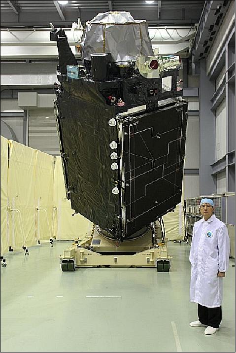
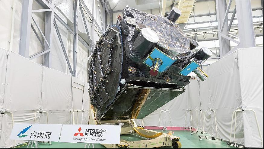
• June 16, 2017: QZS-3, a geostationary orbit (GEO) satellite in the Quasi-Zenith Satellite System (QZSS), was exhibited to members of the press on June 15 at Mitsubishi Electric Corporation's Kamakura Works (Kamakura City, Kanagawa). 34)
- A major feature of QZS-3 is its two antennas for message communication used in the QZSS Safety Confirmation Service (Q-ANPI): one expandable S-band antenna with a diameter of 3.2 meters and one fixed Ku-band antenna with a diameter of one meter. QZS-1, QZS-2, and QZS-4 have L-band antennas that are helical array antennas, but QZS-3 uses a flat patch antenna. QZS-3 is also equipped with an SBAS-signal L1Sb antenna to provide positioning satellite error correction and defect information, including to aircraft.
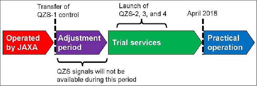
• On February 28, 2017, JAXA discontinued the operation of QZS-1, the First Quasi-Zenith Satellite Michibiki-1. Control was transferred to the Cabinet Office. 35)
- Control of the first Quasi-Zenith Satellite (QZS-1), which was operated until now by JAXA (Japan Aerospace Exploration Agency), has been transferred to the Cabinet Office on February 28, 2017. 36)
- After the transfer of control, test operations were started by Quasi-Zenith Satellite System Services Inc. (QSS), the company consigned to conduct the Business for Operation, etc., of the QZSS (Quasi-Zenith Satellite System).
- Adjustments are required to confirm performance and compatibility with ground systems built by QSS before the start of the trial services. This adjustment period is expected to last around one month after the transfer of control. During this period, users will not be able to use QZS signals due to temporary signal transmission outages and alert flag (*) setting.
- The trial service start date will be announced on this website after it is determined. (*) Many receivers check alert flags and ignore satellites that do not have such flags set. Therefore, they do not impact positioning results.
- The trial services will offer services with the same performance as the operation starting in FY2018, sequentially and on a provisional basis. The services to be offered are outlined on this website's User Interface Specifications page.
- Information about provided services after the transfer of QZS-1 control: Information about provided services will be available on this website's Operational status/NAQU (Notice Advisory to QZSS Users) information page after the trial service start.
NAQU information was sent via email when QZS-1 was operated by JAXA. However, this information will instead be posted on Twitter. To view this information, please follow @QZSS_Status on Twitter. 37)
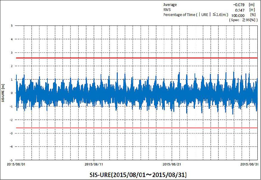
• October 31, 2015: Since June, 2011, QZS-1 has provided navigation signals with good quality, satisfying continuously the system performance specifications. The SIS/URE (Signal-in-Space/User Range Error) for QZS-1 is 40 cm (rms) level which is comparable with those for the GPS Block IIR (M, Modernized) and GPS IIF (Follow-on) satellites. During the month of August 2015 (Figure 16), an rms of 34 cm (rms) was obtained (Ref. 17).
• July 24, 2013: Joint Announcement on US-Japan GPS cooperation. Both Governments reaffirmed that continued close cooperation in the area of GNSS will contribute to the peaceful development of the Asia-Pacific region and promote global economic growth. Both Governments reaffirmed the importance of providing open access to basic GNSS services for peaceful purposes, free of direct user fees.
• As of January 2013, the QZS-1/Michibiki spacecraft is broadcasting the L1-SAIF and Li-SAIF+ messages in parallel. The objective is to improve to performance accuracy for the user communities (Ref. 64).
• Dec. 2012: QZS-1 is equipped with two rubidium atomic clocks, Clock 1 for the operation system and Clock 2 for the spare system, to construct the redundant structure. The former is currently used for generating positioning signals. On Dec. 19, 2012, the project found an anomaly in Clock 2. So far, the team has not been able to restore its normal operations. The satellite keeps generating and providing positioning signals normally using Clock 1 while investigating the anomaly cause and studying countermeasures. 38)
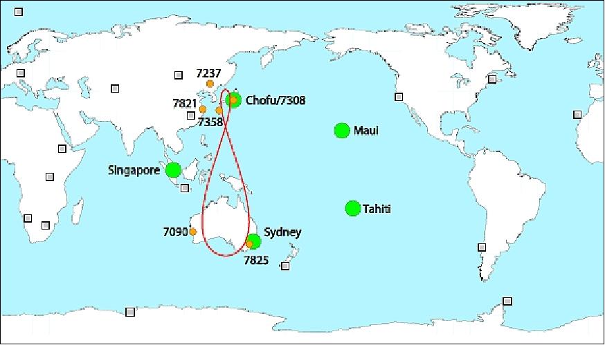
• 2012: With the QZS-1/Michibiki spacecraft declared healthy (i.e. operational) in July 2011, five stations of the CONGO (COoperative Network for GIOVE Observation) are providing a QZSS tracking capability. These stations are: Chofu, Singapore, Sydney, Maui, and Tahiti. Some results are: 39) 40) 41)
- QZS-1 orbits can be determined with sub-meter accuracy from a network of 5 stations only.
- GPS/QZSS differential code biases are on a few ns level with a stability of better than 1 ns.
• On July 14, 2011, the alert flags or positioning signals of L5 and L1C (the modernized signals of GPS) for QZS-1 "Michibiki" were removed after the project confirmed that their quality and reliability satisfy the QZS system user interface specifications. Hence, with the L1-C/A and L2C signals already cleared, all alert flags for the GPS supplementary signals have now been verified. 43) 44)
- Experiment results show that the GPS L1 complementary signal from QZS-1 improves the availability of L1 code positioning approximately 1.7 to 2.5 times when it is compared to GPS only L1 code positioning. Furthermore, simulation results of loosely coupled GPS/Low-cost INS (Inertial Navigation Systems) with and without QZSS are shown. From the results, it is concluded that the system with QZSS makes its use as a future lane-navigation system possible by reducing the positioning errors by more than 30% compared to the system without QZSS. 45)
• In June 2011, JAXA confirmed that the quality and reliability for positioning signals (L1-C/A and L2C) of the QZS-1 (Quasi Zenith Satellite-1) "Michibiki" satisfied the QZS system user interface specifications (IS-QZSS) through technological verification, thus lifting the alert flag for the L1C/A and L2C positioning signals; they were set into the healthy status on June 22, 2011. The project will also remove the alert flag for the remaining positioning signals (L5 and L1C) after their compliance with the IS-QZSS specifications has been verified. 46)
• As of April 2011, the signals from Michibiki have so far not been given a "healthy" clearance. The calibration of the broadcasting ephemeris and clock offset parameters, the parameter tuning on the POD (Precise Orbit Determination) software in the MCS (Master Control Station) are still ongoing. The accuracy of the SIS/URE (Signal-in-Space/User Range Error) has already reached the target value, satisfying the specification of 2.6 m accuracy (95% probability). The alert and health flag will be set to "0" after confirming a stable and continuous good performance; the SIS/URE is already better than the above specification. 47)
Field observations were conducted in various locations (such as at the JAXA Tsukuba Space Center, the Ginza district in Tokyo, etc.). It can be confirmed that the Michibiki signals improve the positioning available time percentage in urban and mountainous regions. The technical demonstrations on signal verification will be continued in various locations of Japan.
• On December 13, 2010, JAXA started regular operations of the Michibiki spacecraft (start of demonstrations). The spacecraft had been under the initial functional verification, referred to as OOC (On Orbit Checkout), for about three months and all the satellite bus and onboard mission devices were confirmed as functioning. However, as JAXA switched all positioning signals to the standard code at 11:48 hours on December 15 (JST,) full-scale technical and application verifications will still be performed by all the organizations (JAXA, NICT, ENRI, SPAC, GSI, etc.). 48)
• By the end of Nov. 2010, initial functional checkout for satellite bus and mission equipment was completed without any major problems. Following initial functional checkout, the initial experiment has been conducted using QZS-1 on orbit. ENRI is conducting the experiment with a car on the road because L1-SAIF signal was originally planned as an augmentation to mobile users with a certain velocity. Preliminary results show the improved accuracy by L1-SAIF augmentation. 49)
• On Oct. 19, 2010, the transmission of the L1-SAIF signal from the L1-SAIF onboard antenna was started. This was followed by the other signals L1-C/A, L2C, L5, L1C, and LEX using the L-band helical antenna. On October 26, 2010 the project started transmitting the signals with their nominal full power, and confirmed that the ground system properly received them. 50)
• On Sept. 27, 2010, JAXA confirmed that Michibiki had been maneuvered into its quasi-zenith orbit - with its center longitude of about 135º through the final orbit control performed on Sept. 27. 2010. 51)
• On Sept. 12, 2010, JAXA confirmed the deployment of the solar array paddles of Michibiki by inspecting telemetry data received at the Santiago Station in Chile. 52)
Sensor Complement
The navigation payload consists of the following elements: 53) 54) 55) 56)
• RAFS (Rubidium Atomic Frequency Standard) clocks
• LTS (L-band signal Transmission Subsystem)
• TTS (Time Transfer Subsystem)
• LRA (Laser Reflector Array).
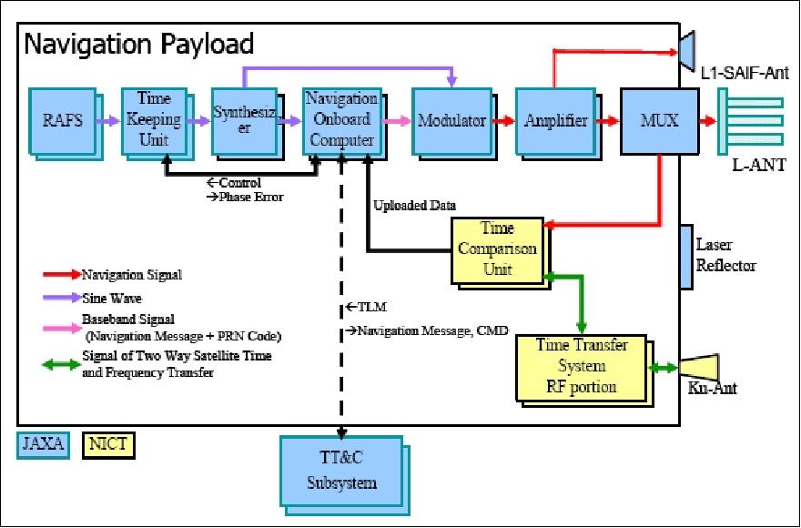
LTS consists of NOC (Navigation On-board Computer), TKS (Time Keeping System), and L-ANT (L-band ANTenna). The main components have redundancies except for L-ANT.
- NOC processes telemetry-command data, generates navigation the message/PRN code and controls atomic frequency and TKS. The software equipped with NOC is capable of the program re-loading by command from the ground system if needed.
- TKS features a high stability VCXO (Voltage-Controlled Crystal Oscillator) with a short-term frequency stability and an atomic clock with a long-term stability. It outputs a standard signal with high stability level using the short-term and long-term inputs. This signal represents the original signal frequency that is being sent from the QZSS. 57) 58) 59)
TTS compares the time between the satellite time and the ground time. It also executes the time delay measurement of the proofreading signal for L-band. It is composed of the time comparison unit and RF portion (including Ku-ANT). Figure 19 shows the composition of QZS-1 navigation payload.
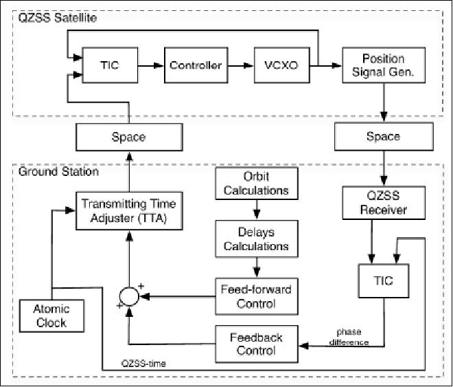
The QZSS synchronization concept is based on the compensation of the ground station satellite delays through prediction. Figure 20 presents a simplified schematic of the remote synchronization system for the onboard crystal oscillator (RESSOX). The precise time available at the ground station (QZS-time) is "advanced" by means of the TTA (Transmitting Time Adjuster) and then uploaded to the satellite. Here, a PLL architecture is implemented to steer the local onboard clock, a VCXO, and keep it locked to the received signal. The output of the VCXO is used to construct the QZSS positioning signal that is then broadcast to the user. The key point is to keep the ground station clock and the onboard VCXO (Voltage Controlled Crystal Oscillator) synchronized by controlling the TTA such that all communication delays are compensated. To do this, a double feedback and feed-forward control loop, based on orbit prediction and delay calculation, are used (Ref. 57).
QZSS Signals
The QZS will transmit six signals on four frequencies; it has GPS interoperable and GPS augmentation capabilities. There are L1C, L1-C/A, and L1-SAIF (Sub-meter class Augmentation with Integrity Function) signals on the L1-band, the L2C signal on the L2-band, the L5 signal on the L5-band, and the LEX (L-EXperimental) signal on the E6-band. The GPS interoperable signals are L1C, L1-C/A, L2C, and L5 signals. These signals are designed to have interoperability with GPS.
The L1-SAIF and LEX signals are GPS augmenting signals (or performance enhancement signals). The L1-SAIF signal has full compatibility with GPS-SBAS and will transmit wide area differential GPS (WDGPS) correction data with an integrity message. In addition, LEX is an experimental signal and augmentation signal with much higher data rate (2 kbit/s) message than the other SBAS signals; it has compatibility with the Galileo E6-CS signal. The horizontal positioning accuracy specifications using the GPS interoperable signals of QZS are equivalent to those of GPS. The target accuracy of L1-SAIF is about 1 m (rms) for user horizontal positioning accuracy. One application candidate for LEX is a surveying application with accuracy of a few centimeters. 60) 61) 62)
Signal name | Center frequency | Comments |
L1-C/A |
| • GPS interoperable signals • Compatibility and interoperability with existing and future modernized GPS signals |
L1C | ||
L2C | 1227.6 MHz | |
L5 | 1176.45 MHz | |
L1-SAIF | 1575.42MHz | • Compatibility with GPS-SBAS |
L6 (LEX) |
| • Experimental signal with higher data rate message (2 kbit/s) |
Signal | Channel | Frequency | Bandwidth | Min. Rx Power |
OZS-L1C | L1CD |
| 24 MHz | –163.0 dBW |
L1CP | 24 MHz | – 158.25 dBW | ||
QZS-L1-C/A |
| 24 MHz | – 158.5 dBW | |
QZS-L1-SAIF |
| 24 MHz | – 161.0 dBW | |
QZS-L2C |
| 1227.6 MHz | 24 MHz | – 160.0 dBW |
QZS-L5 | L5I | 1176.45 MHz | 25 MHz | – 157.9 dBW |
L5Q | 25 MHz | – 157.9 dBW | ||
QZS-LEX | L6 | 1278.75 MHz | 42 MHz | – 155.7 dBW |
Time reference : QZSST (Quasi Zenith Satellite System Time) |
Geodetic reference : JGS (Japan satellite navigation Geodetic System) |
Parameter | Specification | Simulation result |
SIS/URE (Signal-in-Space/User Range Error) | < 1.6 m (95%) | 1.5 m (95%) |
Single frequency user | 21.9 m (95%) | 7.02 m (95%) |
Dual frequency user | 7.5 m (95%) | 6.11 m (95%) |
Legend to Table 7: The user positioning accuracy is defined as the position accuracy of the combined GPS L1-C/A and QZSS L1-C/A signals for the single frequency user, and L1-L2 for the dual frequency user.
QZSS is broadcasting the GPS augmentation information on the GPS L1 frequency for experiments. For this purpose L1-SAIF (submeter-class augmentation with integrity function) signal has been developed based on SBAS standard. The ENRI (Electronic Navigation Research Institute) of Japan has been responsible for development of L1SMS (L1-SAIF Master Station). 63)
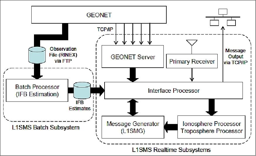
The L1-SAIF signal can provide WDGPS (Wide-Area Differential Global Positioning System) correction data, its positioning accuracy is 1 m (1σ rms) except in cases of large multipath error and large ionospheric disturbance. - In order to achieve seamless wide-spread service area independent of the baseline distance between user location and monitor station, the WADGPS provides vector correction information, consisting of corrections such as satellite clock, satellite orbit, ionospheric propagation delay, and tropospheric propagation delay.
Introduction of the L1-SAIF+ Message
The objective of the orbiting QZS-1 spacecraft is to broadcast several types of signals to demonstrate their usefulness. The "L1-SAIF (Sub-meter class Augmentation with Integrity Function) signal" is one of these signals, its main purpose is the augmentation to satellite positioning using the SBAS (Satellite Based Augmentation System). The L1-SAIF message has been designed in particular for mobile device users to obtain an augmented accuracy in the sub-meter range. 64)
The "L1-SAIF+" message is an expansion of the L1-SAIF message to improve the performance range of augmentation messages.
The L1-SAIF+ messages consist of two categories: "SBAS-compatible" messages and "SBAS-incompatible" ones. The former message has the function mainly for augmentation of satellite-positioning signal as same as the function of SBAS, and the latter message mainly offers the information for users to shorten the TTFF (Time To First Fix).
• SBAS-compatible messages contain various types of information for differential correction, including satellite orbit error, ionospheric delay and others.
• SBAS-incompatible messages in "L1-SAIF+" have unique functions: one of them is to help users to catch the signals from positioning satellites in shorter time. The information for correcting orbital position and clock errors for these 10 satellites are distributed by this type of message. In addition, the "L1-SAIF+" messages have a function to include short messages for emergency cases, such as disaster relief.
As of January 2013, augmentation messages only for the GPS satellites are generated by the system and broadcasted via QZS-1. By adding the augmentation message for QZS, i.e. broadcasting the L1-SAIF and Li-SAIF+ messages in parallel, it is expected to improve the accuracy in positioning.
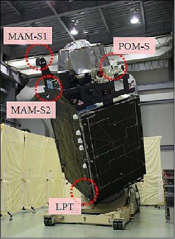
Secondary Payloads for Environmental Monitoring on QZS-1
TEDA (TEchnical Data Acquisition experiments)
The TEDA package consists of three types of sensors: LPT (Light Particle Telescope) including APS-B (Alpha particle and Proton Sensor-B) and ELS-A (Electron Sensor-A), MAM (Magnetometers), and POM (Potential Monitors). The overall objective of the TEDA payloads is to measure the environment of the inclined, elliptical geosynchronous orbit. The measured data will be used to improve the design of the following fleet and to produce for JAXA a model of the unique orbital environment. 65)
LPT (Light Particle Telescope)
LPT includes sensors of two types: APS-B (Alpha particle and Proton Sensor-B) and ELS-A (Electron Sensor-A. They are designed to detect, discriminate, and analyze energy of charged particles including electrons, protons, and alpha particles. They cover a much wider energy range than conventional telescopes through their complementary functions. APS-B can observe down to 1.5 MeV for protons and ELS-A can observe down to 0.03 MeV for electrons as their lower limit. Observations in these measurement ranges are important for investigating the surface charging effect. They can also provide measurements up to 250 MeV for protons and 1.4 MeV for electrons in the upper limit. Observations in these measurement ranges are important for investigating the internal charging effect and the single event effect on electronics devices.
Observable particle | proton, deuteron, tritium, helium |
Measurement range | proton : 1.5 MeV ~ 250 MeV |
Counting ability | 5×10⁴ event/s |
Geometric factor | 0.0085 cm2 sr |
FOV (Field of View) | ±21.8º |
Time resolution | 1 s |
Observable particle | electron |
Measurement range | electron : 0.03 MeV ~ 1.4 MeV |
Counting ability | 5 x10⁴ event/s |
Geometric factor | 0.0442 cm2 sr |
FOV | ±21.8º |
Time resolution | 1 s |
Initial data of LPT: Figure 23 shows the differential proton flux in each channel of APS-B around February 15, 2011 when an X-class solar flare occurred. The horizontal axis shows the time from February 14, 0:00 (UT) to February 16, 6:00 (UT) and the vertical axis shows the differential flux. This graph shows growing low-energy protons about 10 hours after the flare, particles of less than 10 MeV two digits increase, less than 30 MeV particles one digit increase. Compared with solar wind data of the ACE mission and the X-ray data of GOES, in spite of the solar wind is calm before and after the flare, an increase of the proton flux was observed after the flare, particles from the sun flow directly.
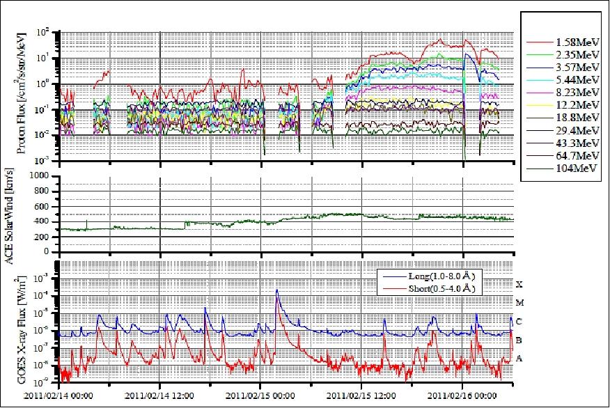
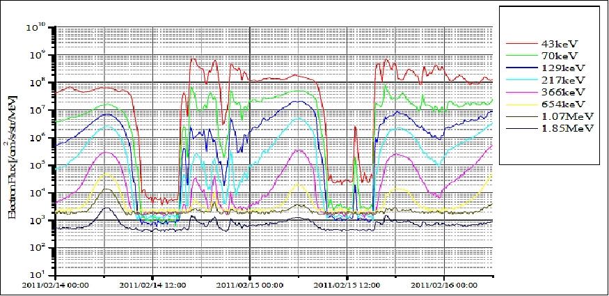
Figure 24 shows the differential electron flux in each channel of ELS-A around February 15, 2011. The axis definition and the time range are same as Figure 23. The graph shows the growing low-energy electrons about 10 hours after the flare occurrence, particles of less than 200 keV increase.
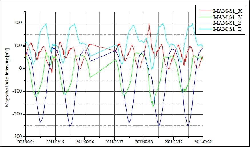
MAM (Magnetometer)
The objective of MAM is to measure magnetic field strength on the QZS-1 orbit to obtain the technical data of the satellite space environment. MAM consists of a two sensor assembly, MAM-S1 (MAM Sensor-1) is mounted on top of the antenna tower away from the satellite assembly and MAM-S2 (MAM Sensor-2) is mounted on the antenna tower base. The two MAM sensors measure the magnetic field between the tip of the antenna tower and the base, identify and distinguish the magnetic field gradient from the satellite; they provide an improved measurement accuracy due to the redundant system.
• Measurement range of MAM: ±65536 nT and ±4096 nT
• Time resolution: 1 second.
Initial data of MAM: Figure 25 shows the magnetic field intensity data of the X, Y, Z directions and the synthesis of 3-axis around February 15, 2011. The horizontal axis shows the time from February 14, 0:00 (UT) to February 20, 0:00 (UT). These data are corrected for the residual magnetic field in each axis. The graph shows the magnetic field disturbance caused by solar wind from about 3 days after the flare occurrence.
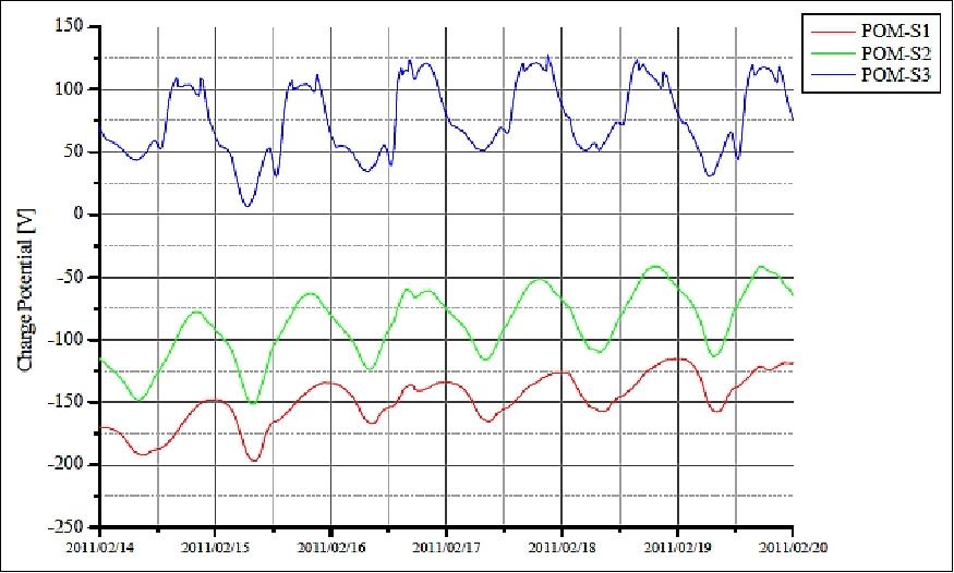
POM (Potential Monitor)
The objective of POM is to measure relative to the surface potential of the satellite assembly for which the three samples measured assessment of the potential charge. The measurement results output to TEDA is in the format of a serial telemetry stream. POM is supplied via the primary power of the powered satellite bus. The experiment started by the ON command from satellite system.
• Measurement range: -10 kV ~ +5 kV
• Resolution: 12 bit
• Measurement accuracy: ±5 % (full scale)
• Time resolution: 1 second.
Initial data of POM: Figure 26 shows the charge potential data of POM around February 15, 2011. These data were collected from three types of test samples of POM, and show a daily periodic variation.
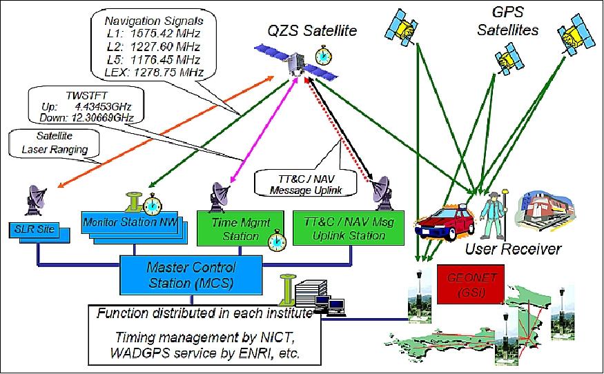
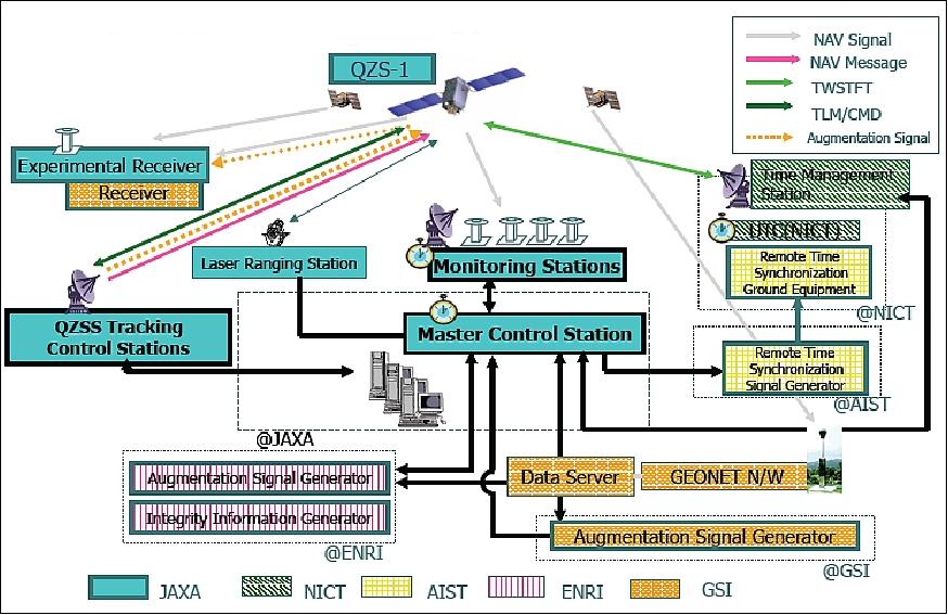
Ground Segment
QZS uses dedicated ground station antennas with continuous visibility and permanent contact like a GEO satellite. The C-band RF communication links are being used for tracking, telemetry and command operations. The QZS ground system consists of the following elements:
• MCS (Master Control Station): The MCS acts as a focal point of QZSS payload operation. It determines the precise orbits of QZSS and generates the navigation message for uplink. It will satisfy high availability requirements using a hot-redundant system.
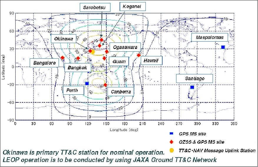
• MS (Monitoring Station): About 10 monitoring stations will be situated in Japan and in Asian/Oceania regions to receive QZS and GPS signals for precise estimation of QZS orbit & clock parameters with a correlation for those of GPS. The GPS augmentation signals processed by MS (or by other MS stations) are to be sent to MCS where QZSS and other GNSS orbits and times are estimated and propagated to predict future satellite positions and system times. Based on the results of orbit and time estimates and predictions, navigation messages are generated and sent to the TCS (Tracking and Control Stations).
• TCS (Tracking and Control Station): The TCS operations for satellite bus and TT&C ground stations control are collocated with MSC. The main TT&C ground station will be located in the Okinawa prefecture, whereas the TCS will be at JAXA's Tsukuba Space Center throughout the first stage of QZSS. The GEO satellite operation system can be applied with minimum modification for the QZSS since the QZSS constellation provides continuous visibility. At the TCS , the navigation message is uploaded to the QZS On-board Control Computer by way of the TT&C. - On-board the QZS, a signal with the navigation message superimposed is generated and transmitted to Earth via the L-band transmission antenna and the L1-SAIF transmission antenna.
JAXA's third-generation SMACS (Spacecraft Management And Control System), is used for TCS control. SMACS has the following major features:
- The system is useful from the spacecraft integration phase as a check-out system to prepare reliable and seamless spacecraft databases.
- Mission-specific software modules may be added easily using legacy, platform-independent and operating-system independent software because the system is implemented in JAVA language. This feature will be very beneficial when the system is extended to the second stage of QZSS to support all satellites in the constellation at the same time.
- Special attention is given to spacecraft control automation. An XML-based computerized spacecraft operational procedure, which enables automatic telemetry checking and telecommand sending, is adopted in the system.
References
1) N. Inaba, A. Matsumoto, H. Hase, S. Kogure, M. Sawabe, K. Terada, "Design Concept of Quasi Zenith Satellite System," 58th IAC (International Astronautical Congress), International Space Expo, Hyderabad, India, Sept. 24-28, 2007, IAC-07-B2.1.032) "JAXA home page of QZS-1," URL: http://www.jaxa.jp/projects/sat/qzss/index_e.html
3) M. Sawabe, "Status of QZSS Project," Munich Satellite Navigation Summit 2006, Feb. 22, 2006, Munich, Germany, URL: http://www.munich-satellite-navigation-summit.org
/Summit2006/Beitraege/Ses_1_5_Maeda_Sawabe.pdf
4) http://www.jaxa.jp/pr/brochure/pdf/04/sat12.pdf
5) F. Wu, N. Kubo, A. Yasada, "Performance Evaluation of GPS Augmentation Using Quasi-Zenith Satellite System," URL: http://www.ics.uci.edu/~djp3/classes/2006_01
_01_ICS280/documents/Lecture08/QZSS%20GPS.pdf
6) H. Nishiguchi, "Country Report from Japan to the 45th CGSIC (Civil GPS Service Interface Committee)," Long Beach, CA, USA, Sept. 12-13, 2005
7) J. Gomi, "Quasi-Zenith Satellite System (QZSS): Program Overview," Munich Satellite Navigation Summit 2004, March 23-25, 2004, URL: http://www.munich-satellite-navigation-summit.
org/Summit2004/Beitraege/1Ses6-Gomi.pdf
8) I. G. Petrowski, "QZSS - Japan's New Integrated Communication and Positioning Service for Mobile Users," GPS World, Vol. 14, No 6, June 1, 2003, pp. 24-29
9) "Quasi Zenith Navigation System Satellite Service: Interface Specification for QZSS (IS-QZSS)," Tokyo, Japan, JAXA, Version V1.1, July31, 2009, URL: http://qz-vision.jaxa.jp/USE/is-qzss/IS-QZSS_11_E.pdf
10) Noriyasu Inaba, and JAXA QZSS Project Team, "Quasi-Zenith Satellite System Program Update," Proceedings of the ION GNSS 2009, Savannah, GA, USA, Sept. 22-25, 2009
11) Noriyasu Inaba, Satoshi Kogure, Mikio Sawabe, Koji Terada, "Development and utilization promotion status of Quasi-Zenith Satellite System," Proceedings of the 60th IAC (International Astronautical Congress), Daejeon, Korea, Oct. 12-16, 2009, IAC-09.B2.3.4
12) QZSS project team, "Quasi-Zenith Satellite System (QZSS) First Quasi-Zenith Satellite System 'MICHIBIKI'," URL: http://www.jaxa.jp/countdown/f18/pdf/presskit_michibiki_e.pdf
13) Hiroaki Maeda, "QZSS: The Japanese Quasi‐Zenith Satellite System, Program Updates and Current status," Proceedings of ION GNSS 2010, Portland, OR, USA, Sept. 21-24, 2010
14) T. Sakai, S. Fukushima, K. Ito, "Recent Development of QZSS L1-SAIF Master Station," ION ITM 2010, San Diego, CA, USA, Jan. 25-27, 2010, URL: http://www.enri.go.jp/~sakai/pub/itm2010_sakai.ppt
15) S. Pullen, "Worldwide Trends in GNSS Development and their Implications for Civil User Performance and Safety," URL: http://waas.stanford.edu/~wwu/papers/gps/PDF/PullenJapanGNSS07.pdf
16) Shigeru Matsuoka, "Service Status of QZSS," APRSAF-15 (15th Session of Asia-Pacific Regional Space Agency Forum) Hanoi, Vietnam, Dec. 9-12, 2008, URL: http://www.aprsaf.org/data/aprsaf15_data/csawg/CSAWG_6d.pdf
17) "Project Overview of the Quasi-Zenith Satellite System," 2015 PNT (Positioning Navigation and Timing) Advisory Board, Oct. 31, 2015, URL: http://www.gps.gov/governance/advisory/meetings/2015-10/murai.pdf
18) Hiroyuki Miyamoto, Motohisa Kishimoto, Erika Myojin, Satoshi Kogure, "Model-based design of Ground Segment for Quasi-Zenith Satellite System," Proceedings of SpaceOps 2012, The 12th International Conference on Space Operations, Stockholm, Sweden, June 11-15, 2012, URL: http://www.spaceops2012.org/proceedings/documents/id1292677-Paper-003.pdf
19) H. Miyamoto, M. Kishimoto, H. Hase, M. Sawabe, K. Terada, "Design of Quasi-Zenith Satellite Navigation System and ground segment," Proceedings of the 26th ISTS (International Symposium on Space Technology and Science) , Hamamatsu City, Japan, June 1-8, 2008, paper: 2008-f-03
20) Nobuhiro Kajiwara, Yosuke Yamamoto , Mikio Sawabe, Satoshi Kogure, Takashi Tsuruta, Motohisa Kishimoto, Yoshihisa Kawaguchi, "Overview of Precise Orbit and Clock Estimation for Quasi-Zenith Satellite System and Simulation Results," Proceedings of the 27th ISTS (International Symposium on Space Technology and Science) , Tsukuba, Japan, July 5-12, 2009, paper: 2009-d-35
21) Erika Myojin, Akihiro Matsumoto, Norijasu Inaba, Koji Terada, "Key Features of Quasi Zenith Satellite Bus System," Proceedings of the 26th ISTS (International Symposium on Space Technology and Science), Hamamatsu City, Japan, June 1-8, 2008, paper: 2008-j-07
22) Satoshi Kogure, "QZSS (Quasi-Zenith Satellite System) Update," ICG Expert Meeting on Global Navigation Satellite Systems and Services, Montreal, Canada, July 15, 2008, URL: http://www.unoosa.org/pdf/icg/2008/expert/2-4b.pdf
23) Satoshi Kogure, "QZSS in Asia and Oceania Region," APRSAF-15 (15th Session of Asia-Pacific Regional Space Agency Forum) Hanoi, Vietnam, Dec. 9-12, 2008, URL: http://www.aprsaf.org/data/aprsaf15_data/csawg/CSAWG_6a.pdf
24) Satoshi Kogure, QZSS Project Team, "Current Status of Quasi-Zenith Satellite System," ICG (International Committee on GNSS) WGA Meeting, Vienna Austria, July 30-31, 2009, URL: http://www.oosa.unvienna.org/pdf/icg/2009/workgroupinterop/05.pdf
25) Noriyasu Inaba, Akihiro Matsumoto, Hidemi Hase, Satoshi Kogure, Mikio Sawabe, Koji Terada, "Design concept of Quasi Zenith Satellite System," Acta Astronautica, Volume 65, Issues 7-8, October-November 2009, Pages 1068-1075
26) Yoshiyuki Ishijima, Noriyasu Inaba, Akihiro Matsumoto, Koji Terada, Hiroo Yonechi, Hitoshi Ebisutani, Shinichi Ukawa, Takeshi Okamoto, "Design and Development of the First Quasi-Zenith Satellite Attitude and Orbit Control System," Proceedings of the 2009 IEEE Aerospace Conference, Big Sky, MT, USA, March 7-14, 2009
27) "Launch Result of the First Quasi-Zenith Satellite 'MICHIBIKI' by H-IIA Launch Vehicle No. 18," JAXA Press Release, Sept. 11, 2010, URL: http://www.jaxa.jp/press/2010/09/20100911_h2af18_e.html
28) http://www.jaxa.jp/countdown/f18/index_e.html
29) "Quasi-Zenith Satellite System," Office of National Space Policy, Cabinet Office, Government of Japan, Proceedings of the 50th Session of Scientific & Technical Subcommittee of UNCOPUOS, Vienna, Austria, Feb. 11-22, 2013, URL: http://www.oosa.unvienna.org/pdf/pres/stsc2013/tech-39E.pdf
30) "JAXA's 'Guiding' H-IIA Successfully Soars as a Beacon in the Sky," Satnews Daily, June 1, 2017, URL: http://www.satnews.com/story.php?number=779699703
31) "Launch Schedule of MICHIBIKI No. 2 Aboard H-IIA Launch Vehicle No. 34," JAXA Press Release, April 10, 2017, URL: http://global.jaxa.jp/press/2017/04/20170410_h2af34.html
32) Stephen Clark, "Japan launches navigation satellite after week-long delay," Spaceflight Now, August 19, 2017, URL: https://spaceflightnow.com/2017/08/19/japan-launches
-navigation-satellite-after-week-long-delay/
33) Stephen Clark, "Successful H-2A rocket launch rounds out Japanese navigation network," Spaceflight Now, October 09.2017, URL: https://spaceflightnow.com/2017/10/09/successful-h-2a-
rocket-launch-rounds-out-japanese-navigation-network/
34) "Exhibition of the QZS-3," QZSS, June 16, 2017, URL: http://qzss.go.jp/en/events/kamakura_170616.html
35) "QZS-1 off to the Cabinet Office's Control," JAXA, Feb. 22, 2017, URL: http://global.jaxa.jp/projects/sat/qzss/index.html
36) "QZS-1 Control Will be Transferred to the Cabinet Office, Followed by an Adjustment Period Before the Trial Service Start," Feb. 22, 2017, URL: http://qzss.go.jp/en/overview/notices/transfer_170222.html
37) http://sys.qzss.go.jp/dod/en/naqu.html
38) "MICHIBIKI: Current status of rubidium atomic clock 2," JAXA, Dec. 20, 2012, URL: http://www.jaxa.jp/projects/sat/qzss/topics_e.html
39) Peter Steigenberger, Carlos Rodriguez-Solano, Urs Hugentobler, Andre Hauschild, Oliver Montenbruck, "Orbit and Clock Determination of QZS-1 Based on the CONGO Network," ION International Technical Meeting, Newport Beach, CA, USA, Jan. 30 - Feb. 1, 2012, URL: http://www.iapg.bv.tum.de/mediadb/2548800/2548801/C3_Steigenberger_ppt.pdf
40) Peter Steigenberger, Urs Hugentobler, Carlos Rodriguez-Solano, Andre Hauschild, "Precise Orbit Determination of QZS-1," URL: http://www.iapg.bv.tum.de/mediadb/2104189/2104190/steigenb_agu11_QZSS.pdf
41) M. Nakamura, Y. Takahashi, J. Amagai, T. Gotoh, M. Fujieda, R. Tabuchi, T. Hobiger, S. Hama, Y. Yahagi, T. Takahashi, S. Horiuchi, "Experimental Results of the Time Comparison Between the QZS-1 and Ground Time Management Stations," ION International Technical Meeting, Newport Beach, CA, USA, Jan. 30 - Feb. 1, 2012, URL of abstract: http://www.ion.org/meetings/abstract.cfm
?meetingID=35&pid=117&t=A&s=2
42) "Quasi-Zenith Satellite-1 "MICHIBIKI" ," JAXA, Dec. 20, 2012, URL: http://global.jaxa.jp/projects/sat/qzss/
43) "MICHIBIKI provides all GPS supplementary signals," JAXA, July 14, 2011, URL: http://www.jaxa.jp/topics/2011/07_e.html
44) M. Kishimoto, E. Myojin, S. Kogure, H. Noda, K. Terada, "QZSS On Orbit Technical Verification Results," Proceedings of ION GNSS 2011, Portland, OR, USA, Sept. 19-23, 2011
45) Y. Sato, M. Miya, Y. Shima, M. Saito, J. Takiguchi, J. Yamashita, "Improvement of Positioning Performance in Urban Canyons Utilizing QZSS," Proceedings of ION GNSS 2011, Portland, OR, USA, Sept. 19-23, 2011
46) "First Quasi-Zenith Satellite 'MICHIBIKI' Begins Providing Positioning Signals (Lifting the alert flag)," JAXA Press Release, June 22, 2011, URL: http://www.jaxa.jp/press/2011/06/20110622_michibiki_e.html
47) Yaka Wakabayashi, Satoshi Kogure, Jiro Yamashita, Hiroaki Tateshita, Motoyuki Miyoshi, "QZSS Field Observation on Multi Locations in Various Conditions," Proceedings of the 28th ISTS (International Symposium on Space Technology and Science), Okinawa, Japan, June 5-12, 2011, paper: 2011-j-01
48) "MICHIBIKI starts technical and application verifications," JAXA, Dec. 15, 2010, URL: http://www.jaxa.jp/projects/sat/qzss/topics_e.html
49) T. Sakai, S. Fukushima, K. Ito, "QZSS L1-SAIF Initial Experiment Results," Proceedings of the 2011 International Technical Meeting of The Institute of Navigation, San Diego, CA, USA, January 24 - 26, 2011
50) "MICHIBIKI begins transmitting all positioning signals, ground stations confirm them," JAXA, Oct. 26, 2010, URL: http://www.jaxa.jp/projects/sat/qzss/topics_e.html
51) "First Quasi-Zenith Satellite MICHIBIKI Injection into the Quasi-Zenith Orbit," Sept. 27, 2010, URL: http://www.jaxa.jp/press/2010/09/20100927_michibiki_e.html
52) "First Quasi-Zenith Satellite MICHIBIKI Flight Status," Sept. 12, 2010, URL: http://www.jaxa.jp/press/2010/09/20100912_michibiki_e.html
53) M. Kishimoto, H. Hase, A. Matsumoto, T. Tsuruta, S. Kogure, N. Inaba, M. Sawabe, T. Kawanishi, S. Yoshitomi, K. Terada,. "QZSS System Design and its Performance," ION NTM (National Technical Meeting) 2007, San Diego, CA, USA, January 22-24, 2007
54) T. Sakai, S. Fukushima, N. Takeichi, K. Ito, "Augmentation Performance of QZSS L1-SAIF Signal," ION NTM (National Technical Meeting) 2007, San Diego, CA, USA, January 22-24, 2007
55) Y. Takahashi, J. Amagai, S. Hama, M. Fujieda, K. Kimura, "The On-board and Ground Time Management System of QZSS," ION NTM (National Technical Meeting) 2007, San Diego, CA, USA, January 22-24, 2007
56) T. Iwata, Y. Kawasaki, M. Imae, T. Suzuyama, T. Matsuzawa, S. Fukushima, Y. Hashibe, N. Takasaki, K. Kokubu, A. Iwasaki, F. Tappero, A. Dempster, Y. Takahashi, "Remote Synchronization System of Quasi-Zenith Satellites Using Multiple Positioning Signals for Feedback Control," ION NTM (National Technical Meeting) 2007, San Diego, CA, USA, January 22-24, 2007
57) F. Tappero, A. Dempster, T. Iwata, M. Imae, Y. Takahashi, "Remote Control System for the Quasi-Zenith Satellite Crystal Oscillator Based On the Two-Way Time Transfer Method," IGNSS (International Global Navigation Satellite Systems Society) Symposium 2006, Surfers Paradise, Australia, July 17-21, 2006, URL: http://www.gmat.unsw.edu.au/snap/publications/tappero_etal2006b.pdf
58) F. Tappero, A. Dempster, T. Iwata, "SBAS with Ground Based Atomic Reference Station," Jan/Feb. 2007, URL: http://www.gmat.unsw.edu.au/snap/publications/tappero_etal2007a.pdf
59) M. Fukui, A. Iwasaki, T. Iwata, T. Matsuzawa, Y. Hashibe, "Remote Synchronization System for Onboard Crystal Oscillator (RESSOX) Experiments Using L1CA/L1C/L2C/L5 Generator," Proceedings of the 26th ISTS (International Symposium on Space Technology and Science) , Hamamatsu City, Japan, June 1-8, 2008, paper: 2008-f-06
60) S. Kogure, M. Kishimoto, M. Sawabe, K. Terada, "Introduction of IS-QZSS (Interface Specification for Quasi Zenith Satellite System)," Proceedings of the 20th International Technical Meeting of the Satellite Division of the Institute of Navigation, ION GNSS 2007, Sept. 25-28, 2007, Fort Worth, TX, USA
61) "Interface Specification for QZSS (IS-QZSS)," URL: http://qzss.jaxa.jp/is-qzss/index_e.html
62) T. Sakai, S. Fukushima, N. Takeichi, K. Ito, "Implementation of the QZSS L1-SAIF Message Generator," ION NTM (National Technical Meeting), San Diego, CA, Jan. 28-30, 2008
63) Takeyasu Sakai, Hideki Yamada, Kazuaki Hoshinoo, Ken Ito, "QZSS L1-SAIF Supporting GPS/GLONASS Multi-Constellation Augmentation," Proceedings of ITM 2013 (International Technical Meeting) of The Institute of Navigation, San Diego, Ca, USA, January 28-30, 2013
64) Ryo Iwama, Hiroshi Soga, Kimikazu Odagawa, Yasuhiro Masuda, Tomoya Osawa, Mitsuhiro Matsumoto, "Operation of Sub-meter Class Augmentation System and Demonstration Experiments with Quasi-Zenith Satellite "MICHIBIKI" in 2011-2012 and Further Challenge in 2012," Proceedings of ITM 2013 (International Technical Meeting) of The Institute of Navigation, San Diego, Ca, USA, January 28-30, 2013
65) Satoshi Furuhata, Haruhisa Matsumoto, Takahiro Obara, "Overview of Initial Observation Data of Technical Data Acquisition Equipments on the first Quasi-Zenith Satellite," Proceedings of the 28th ISTS (International Symposium on Space Technology and Science), Okinawa, Japan, June 5-12, 2011, paper: 2011-r-58
66) QZSS status as of July 15, 2008, URL: http://www.unoosa.org/pdf/icg/2008/expert/2-4b.pdf
67) Takeyasu Sakai, Hideki Yamada, Sonosuke Fukushima, Ken Ito, "Generation and Evaluation of QZSS L1-SAIF Ephemeris Information," Proceedings of ION GNSS 2011, Portland, OR, USA, Sept. 19-23, 2011
68) QZSS Project Team, "Current status of Quasi-Zenith Satellite System," 4th International Committee on GNSS, Saint Petersburg, Russia, Sept. 14-18, 2009, URL: http://www.oosa.unvienna.org/pdf/icg/2009/icg-4/05-1.pdf
The information compiled and edited in this article was provided by Herbert J. Kramer from his documentation of: "Observation of the Earth and Its Environment: Survey of Missions and Sensors" (Springer Verlag) as well as many other sources after the publication of the 4th edition in 2002. - Comments and corrections to this article are always welcome for further updates(eoportal@symbios.space)
Spacecraft Launch Mission Status Sensor Complement Secondary Payload Ground Segment References Back to Top