SAPPHIRE (Stanford AudioPhonic Photographic IR Experiment)
Non-EO
Mission complete
UNSA
Quick facts
Overview
| Mission type | Non-EO |
| Agency | UNSA |
| Mission status | Mission complete |
| Launch date | 30 Sep 2001 |
| End of life date | 31 Mar 2005 |
| CEOS EO Handbook | See SAPPHIRE (Stanford AudioPhonic Photographic IR Experiment) summary |
SAPPHIRE (Stanford AudioPhonic Photographic IR Experiment)
SAPPHIRE is a graduate-student microsatellite project within the framework of SQUIRT (Satellite Quick Research Testbed) in SSDL (Space Systems Development Laboratory) at Stanford University and at Washington University, St. Louis, MO. The overall objective is to design, construct and operate a microsatellite. SAPPHIRE's primary mission is to space-qualify a micromachined infrared sensor (PI: T. Kenny).
The SAPPHIRE project started in 1994. It is in effect the first spacecraft designed and fabricated by SSDL's new SQUIRT (Satellite Quick Research Testbed) program. The goal of this project is to produce student engineered satellites capable of servicing state-of-the-art research payloads on a yearly basis. Participation in this program prepares graduate degree students for the SSDL's advanced spacecraft programs and offers a comprehensive educational experience. 1) 2) 3)
Based on student interest and the capabilities of the SSDL's affiliated researchers, the selected missions for the SAPPHIRE spacecraft include:
1) assessing the performance of experimental IR sensors
2) performing digital space photography
3) broadcasting voice synthesized messages.
Spacecraft
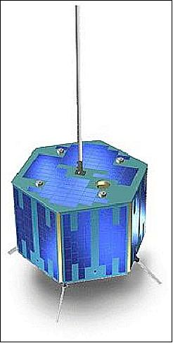
The spacecraft design uses a hexagonal cylinder made from aluminum honeycomb, 44 cm from tip to tip (diameter) and 33 cm tall (including launch interface).The S/C structure consists of four stacked aluminum honeycomb trays, one to a subsystem (from bottom: Power, Communications, CPU, and Sensors), with eight external panels (six sides, top and bottom) upon which the solar cells are mounted.
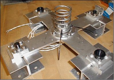
The stacked tray design is made up of four aluminum honeycomb rectangular trays on four threaded rods used as primary load-carrying elements; each tray rests on a set of aluminum spacers (Figure 2). The body-mounted solar panels are fastened to the sides and top of the structure.
The entire hexagonal cylinder, fully loaded and on the launch interface, has a mass of 20 kg. The launch interface has an additional mass of 3 kg. The spacecraft structure was built by students using hand tools and standard milling machines. 4) 5) 6) 7)
ADCS (Attitude Determination and Control Subsystem). The ADCS follows in the footsteps of the early Oscar satellites (AMSAT) to provide a “controlled tumble” with a spin of about 1/3 to 1/2 rpm. Four permanent (ALNICO-V bar) magnets are aligned with the vertical S/C z-axis (providing the primary means of attitude control), forcing the S/C to line up with the local North direction of the Earth's magnetic field. This in turn generates near-nadir pointing in the northern hemisphere (the top face of the S/C is pointing to nadir), a prerequisite for the camera system. In the southern hemisphere, the top face of the S/C looks to the horizon, while the bottom face of the S/C is pointing toward nadir, giving the IR sensors full view of the Earth in this region. [As the latitude of the S/C increases, the S/C pitch angle increases causing SAPPHIRE to ”flip” over at each pole crossing].
A minute spin moment (torque) is induced by the four turnstile transmit antennas on the outside of the S/C, which are painted black on one side, white on the other, to create a spin effect about the Z axis (Note: The solar pressure creates a minute, however constant torque, resulting from black and white painted antennas ). Hysteresis rods are placed perpendicular to the Z-axis to damp nutation about that axis as well as to create a maximum spin rate. The spacecraft attitude is sensed by Earth sensors.
The mass of the ADCS includes 3.1 kg of ballast to ensure proper spin performance, and 2.1 kg more ballast was added to meet launch vehicle requirements.
EPS (Electrical Power Subsystem): The exterior surface of the spacecraft is covered with a mix of GaAs (Gallium Arsenide) and Ge solar cells providing > 8 W of average power (16 W of peak power). The arrays consist of 20 strings of 20 cells each, fabricated by the assistance of Lockheed Martin. A single battery pack of 10 Sanyo NiCd D cells provides 5Ah of secondary power for high-load operations and eclipse.
Because the maximum power generated during an orbit is a small fraction of the battery capacity, no charge control was implemented. This decision simplified subsystem design, reduced the risk of design and workmanship errors, and was in line with the “operational robustness” philosophy. The power conditioning circuitry provides regulated 12 V and 5 V buses to the satellite components. Student-built sensing boards monitor the power subsystem currents, voltages and temperatures.
The power supply and demand balance is monitored by the spacecraft processor through real-time analysis of power conditioning telemetry. A flight manager software module automatically manages component switching based upon user demand and available power. Fine control of bus shunting is achieved through variable power output capability on both communication transmitters.
C&DH (Command and Data Handling) subsystem: The spacecraft CPU is a Motorola 68332 series microcontroller and a student-designed interface board. The student-written operating system is stored in a radiation-hardened EEPROM donated by SEI; the active memory is 1MB of non-hardened military-grade RAM. In case of a software crash or radiation-induced error, the CPU can be reset by ground command through a special function of the communications subsystem.
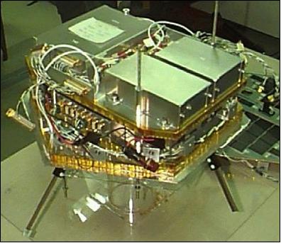
Legend to Figure 2: Two trays have been added to the stack and the through-rods are visible.
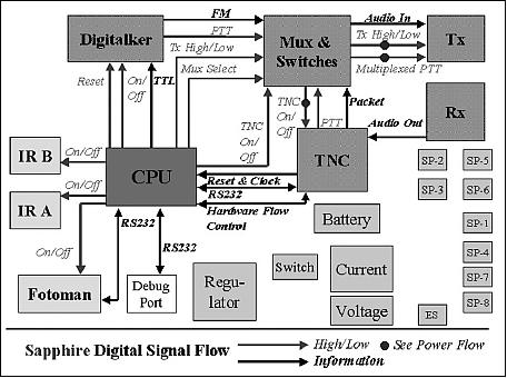
RF communications: The subsystem uses modified Hamtronics kits - commercially available equipment of amateur radio kits and TNC (Terminal Node Controller). The transmitter broadcasts with 2 W of power at 437.100 MHz (UHF). The receiver is at 145.945 MHz (uplink in VHF). Data is transmitted at 1200 baud and uses AFSK encoding, the AX.25 packet protocol, and standard Mode J Amateur Satellite frequencies. The voice downlink utilizes frequency modulation and operates at variable speeds.
The communications subsystem performed better than anticipated; communications were possible from horizon to horizon on most passes using a basic OSCAR station, although there was some slight bias in the transmitter’s oscillator. SAPPHIRE was rendered inoperable for several months beginning in May 2002, and the most-likely error source was a bit flip in the TNC operating code. With the aid of the Amateur community, the hardware-based reset of the TNC was activated and the spacecraft was restored to full operations (Ref. 6).
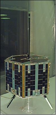
The major flight components for SAPPHIRE were integrated and operated within a year of project inception (1995), and the spacecraft was completed in 1998, as shown in Figure 4. In 2000, the vehicle was transported to Washington University in St. Louis, MO (WU) for final prelaunch preparations (Ref. 6).
SAPPHIRE separation system: The launch vehicle interface was also student-designed and student-built, based on a single hold-down bolt with a single separation spring. 8)
Launch
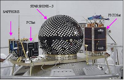
SAPPHIRE was launched as a secondary payload on Sept. 30, 2001 on the Athena-1 vehicle of Lockheed Martin from the Kodiak Launch Complex on Kodiak Island, AK, USA. The primary payload was PICOSat, a microsatellite of the USAF Space Test Program (STP). 9)
The other secondary payloads on this flight were:
• STARSHINE-3 of NRL and the Rocky Mountain NASA Space Grant Consortium
• PCSat (Prototype Communications Satellite) of USNA (US Naval Academy).
The launch of the four payloads is also referred to as the “Kodiak Star Mission.” SAPPHIRE's participation in Kodiak Star was supported by the USNA and the STP (Space Test Program) of DoD (Department of Defense). 10) 11)
Orbit: Near-circular orbit, perigee = 788 km, apogee = 799 km, inclination = 67º, period = 100.73 minutes. 12)
Mission Status
• The SAPPHIRE spacecraft was placed on-orbit in 2001, was fully functional for almost 3 years and partially operational for another 6 months. End of mission in early 2005 (Ref. 6).
• SAPPHIRE met all of its primary mission objectives during its 30 months of full on-orbit operations:
- it characterized the performance of Stanford / JPL (Jet Propulsion Laboratory) micromachined infrared detectors
- it performed photography of the Earth’s surface
- it provided Amateur radio operators with digital and voice communications
- most importantly, it provided a significant education and research platform for participating students.
For example, SAPPHIRE served as an experimental testbed for automated health monitoring research during controlled ground testing as well as during on-orbit operations. In addition, SAPPHIRE saw the most on-orbit activity in unplanned uses: store-and-forward communications for the radio Amateur community and ground station checkout for university satellite projects.
Because of its role as the flagship mission of a new university-class satellite laboratory, and because many SAPPHIRE alumni have key roles in university-class missions at other universities, including both University Nanosat and CubeSat categories, the SAPPHIRE project is an excellent case study in hands-on spacecraft design activities at the university level.
Of all the lessons learned on the SAPPHIRE project, the authors believe that three stand out as most relevant for other university-class missions: operational robustness, mission relevance and modular design (Ref. 6).
The SAPPHIRE mission did not meet expectations of timeliness. SQUIRT spacecraft were envisioned as 1-year development projects; SAPPHIRE took 7 years to launch, and the second SQUIRT spacecraft, Opal, took 5 years.
Sensor Complement
The primary mission objective is to characterize the on-orbit performance of the new generation of infrared horizon detectors (2 THDs were flown), in addition to flying two student instruments, a digital camera and a voice synthesizer. Student research interests are also driving experiments in nontraditional sensing and automated operations.
THD (Tunneling Horizon Detector)
The THD experiment uses a micromachined IR detection system of JPL on-a-chip design, employing the electron-tunneling principle, and operating at room temperature. The sensor is constructed with roughly 1 µm of separation between the membrane and tip. To pull the membrane close enough to enable tunneling currents, an electrostatic force is created by applying a large voltage (100s of Volts) between the membrane and the deflection electrodes. An external circuit controls this “deflection voltage” to maintain a constant tunneling current. 13) 14) 15) 16)
THD is a fixed narrow-FOV horizon detector. Its primary output is an analog signal that triggers on the Earth/space and space/Earth horizon crossings. The THD assembly contains a TIS (Tunneling Infrared Sensor) with 2 independent sensing elements and corresponding electronic circuitry. THD is sensitive to the entire infrared spectrum with an average sensitivity of 1,500 V/W.
The assembly is fastened to the payload tray and looks out a slit aperture from the side of the spinning spacecraft, perpendicular to the spin axis (“scanning” is provided by the spinning S/C). The slit aperture limits the FOV to 6º in the transverse spin plane and to 22º in the vertical plane. The tunneling element outputs are proportional to the level of variation in incident infrared radiation on TIS and consist of a 3.0 V signal + 1/400 of the tunneling high voltage + the tunneling signal disturbance.
THD mass, size | 0.170 kg, 46 mm x 184 mm x 31 mm |
Power consumption | 0.2 W (idle), 0.9 W (operation) |
Inputs | 5 V, 12 V, ground, and a digital high voltage on/off line |
Outputs | 4 analog signals (0-5 V) and 4 ground lines (tunneling element 1, tunneling element 2, high voltage level, and payload temperature) |
FOV (Field of View) aperture | 6º FOV in the spin plane, 22º FOV in the vertical plane, |
Spectral band | multispectral (infrared) |
Temperature constraints | -10ºC to - 60ºC (storage), and 0 - 50ºC (operation) |
Detector responsivity | 1,500 V/W |
Sample frequency | 100 Hz nominal, (10 Hz minimum) |
Electrical connections | input signal DB-9 connector and 1 output signal DB-9 connector |
The THD flight tests involved detecting transitions in IR radiation as the spacecraft slowly rotated the sensor FOV across the Earth’s limb. These tests were conducted in a range of orbital conditions and light levels. Two of the sensors failed during ground testing but were not replaced before launch. A third sensor failed soon after launch, though it is not clear from the telemetry whether this was due to a failure of the sensor itself or of the A/D converter used to sample data. The fourth sensor was fully functional for more than 30 months and demonstrated on-orbit suitability of the THD design.
The THD experiment suffered from SAPPHIRE's long development cycle. THD was a relatively “new” technology at the start of the project, but in the 7-year gap from conception to flight data, the THDs had become old technology and, more importantly, the PI had shifted his research focus to terrestrial applications. Therefore, while the flight data validated the basic design of the sensor, the delay in validation hampered the data’s relevance (Ref. 6).
Digital Camera
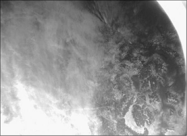
A commercially available B&W CCD camera (model “Fotoman Plus” of Logitech). The objective is to obtain imagery in the northern hemisphere of about 1 km spatial resolution. The capabilities of the digital camera include JPEG image compression, storage in DRAM of up to 32 (496 x 360 pixel array) images with 8 bit gray scale in compressed form. A compressed image has a volume of about 23 kbytes. The Digital Camera has a mass of 0.450 kg and an average power consumption of 2 W.
The Fotoman camera was modified for flight by disabling the flash assembly, adding a power switch, conformal coating the electronics, and adding sealants to stiffen components for launch. Software modifications permitted reloading the camera drivers in case of radiation upset.
The Fotoman experiment illustrates the risks of student-built payloads using commercial electronics. As shown in Figure 7, the camera is capable of delivering Earth images with approximately 1 km resolution; however, the Earth albedo is too bright for the built-in light compensation and images must be acquired during dusk and dawn. The camera must be warmed up for several orbits before operation, due to SAPPHIRE's higher-than-designed orbit altitude (Ref. 6).
Voice Synthesizer
The objective of the “Digitalker” is to test and illustrate a new communication approach which might be of interest to the Amateur Radio community. There are certainly also some applications seen in the field of education. The Digitalker can be received by radios (hand-held or whatever) when the satellite is overhead, capable to “talk” to an audience, giving for instance a lesson on a particular subject. The on-board voice synthesizer is based on the commercial V8600 Speech Synthesizer of RC Systems with some modifications by the student team.
SAPPHIRE's voice synthesizer converted an uploaded text message into an FM-modulated speech which was broadcast by the vehicle’s radio. The RC Systems V8600 was another consumer-grade product modified in a manner similar to the Fotoman. This student-sponsored payload was used to support Amateur Radio events such as the 100th anniversary of Marconi’s first transatlantic radio transmission and the annual Army–Navy game.
Health Monitoring Beacon
A pseudo-payload, designed by students, with the objective to assess attitude determination by using the solar panels as a differential sun sensor, referred to as ODDSS (Omni-Directional Differential Sun Sensor). 17)
One proposed approach for reducing the cost of spacecraft operations is to automate routine functions such as health monitoring. In this concept, the spacecraft is responsible for monitoring its own telemetry and assessing its state of health. Early versions of beacon-based health monitoring were demonstrated on NASA’s Deep Space 1 mission and in SAPPHIRE ground tests.
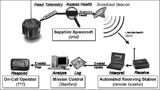
As shown in Figure 8, the on-board software compares vehicle health sensors against a customized state-dependent limit table. The spacecraft health was abstracted to one of four values depending on how quickly ground operators needed to respond. This 2 bit health beacon could be received and decoded by SSDL-developed receive-only stations, notifying mission control of the results by electronic mail.
In this manner, all spacecraft sensor data were abstracted into a 2-bit state value that indicated whether SAPPHIRE could continue to perform its mission. The response from mission control depended on the health assessment, from storing the update in the system database to paging the operator on call and rescheduling the network. Instead of collecting this information during manned contacts using a few high-cost ground stations, spacecraft health could be automatically monitored using many low-cost receiving stations. Ground experiments and analyses indicated that four receiving stations placed at SSDL university partners around the world would provide significant cost savings and greatly reduce the time between the occurrence of an anomaly and operator notification.
The beacon monitoring system was extensively ground-tested using SAPPHIRE from 1997–1999. Student researches provided the first verification of beacon monitoring technology for LEO orbits, developed a suite of conceptually based validation metrics, and used those metrics to validate the cost-effectiveness of the technology for a niche of LEO missions, including university-class small satellites. Thus, the beacon monitoring experiment validated the use of university-class spacecraft to perform engineering research.
Amateur Radio Service
SAPPHIRE’s intended Amateur radio function was to teach pre-college students about spacecraft and radio communications using the camera and voice synthesizer payloads. Instead, SAPPHIRE was of greater use to the Amateur community as a digital repeater, bulletin board and test node for the APRS (Automatic Position Reporting System). Because SAPPHIRE uses COTS Amateur communication equipment, worldwide Amateur operators were able to use SAPPHIRE in unexpected ways. The Amateur community also proved invaluable assistance in forcing a spacecraft reset after a lockup of the communications software.
Educational Tool
SAPPHIRE was designed and built by students at Stanford University, readied for flight by students at Washington University (WU) in St. Louis, MO, and operated by students at the USNA (US Naval Academy) and at SCU (Santa Clara University), Santa Clara, CA. At each institution, SAPPHIRE was incorporated into the spacecraft design and operations curriculum. More than 70 Stanford students and 30 WU students directly contributed to the design, fabrication, testing and operations of the spacecraft. In addition, SAPPHIRE was used to calibrate ground stations and train student operators for several schools in the AFRL/NASA/AIAA University Nanosat-3 design competition.
The educational benefits of the SQUIRT program can be informally evaluated by the post-SAPPHIRE careers of participating students; of the dozen graduate students who invested a year or more in the SAPPHIRE project, nine hold significant spacecraft systems or management responsibilities with aerospace contractors, the Air Force or academia, while the other three are involved in strong system-based research and management in industrial or government laboratories.
Similarly, three SAPPHIRE graduates have founded university-class projects at other schools, where their SAPPHIRE experience has been a notable factor in winning NSF (National Science Foundation) and Air Force education and research contracts. As students, SAPPHIR participants presented seven papers in highly competitive student competitions at the AIAA/Utah State University Conference on Small Satellites and the International Telemetry Conference. Furthermore, SAPPHIRE played a central role in experimental research for two doctoral dissertations and three Engineers’ theses projects (Ref. 6).
References
1) Christopher A. Kitts & William H. Kim, “The Design and Construction of the Stanford Audio Phonic Photographic Infrared Experiment (SAPPHIRE) Satellite, May 25, 1994
2) Christopher A. Kitts, Robert J. Twiggs, "The Satellite Quick Research Testbed (SQUIRT) Program," Proceedings of the 8th Annual AIAA/USU Conference on Small Satellites, Logan, Utah, September 16-22, 1994
3) Richard A. Lu, Tanya A. Olsen , Michael A. Swartwout, Robert J. Twiggs, “Building 'Smaller, Cheaper, Faster' Satellites Within the Constraints of an Academic Environment,” June 9, 1995
4) Robert Twiggs, Michael Swartwout, “SAPPHIRE - Stanford's First Amateur Satellite,” AMSAT-NA 16th Space Symposium, Vicksburg, Mississippi, USA, Oct. 16, 1998
5) Michael A. Swartwout, Carlos G. Niederstrasser, Christopher A. Kitts, Rajesh K. Batra, Kenneth P. Koller, “Experiments in automated health assessment and notification for the SAPPHIRE microsatellite,” 2000, URL: http://track.sfo.jaxa.jp/spaceops98/paper98/track5/5f002.pdf
6) Michael Swartwout, Christopher Kitts, Robert Twiggs, Thomas Kenny, Billy Ray Smith, Rick Lu, Kevin Stattenfield, Freddy Pranajaya, “Mission results for Sapphire, a student-built satellite,” Acta Astronautica, Volume 62, Issues 8-9, April-May 2008, pp. 521-538
7) Michael Swartwout, Christopher Kitts, James Cutler, “Case Study for Student-Built Spacecraft,” Journal of Spacecraft and Rockets, Vol. 3 No.3, 2006, pp. 1136-1139
8) Alison A. Nordt, Robert J. Twiggs, “The Design of the SAPPHIRE Separation System and Launch Vehicle Interface,” URL: http://microsat.sm.bmstu.ru/e-library/Construction/SSDL9503.pdf
9) Steven Weis, Lisa Berenberg, “Agile Space Launch,” Crosslink, The Aerospace Corporation, Summer 2009, URL: http://www.aero.org/publications/crosslink/summer2009/03.html
10) “Kodiak Star Spacecraft, United States of America,” URL: http://www.aerospace-technology.com/projects/kodiak/
11) “Athena I - Kodiak Star Mission,” NASA Facts, August 2001, URL: http://www.nasa.gov/centers/kennedy/pdf/167413main_kodiakstar.pdf
12) AMSAT, “Navy-OSCAR 45 (Sapphire),” URL: http://www.amsat.org/amsat-new/satellites/satInfo.php?satID=59
13) “Tunneling Horizon Detector Payload Design,” Stanford University, URL: http://micromachine.stanford.edu/projects/tunneling_sensors/THD/THDPayloadDesign.html
14) T. W. Kenny, W. J. Kaiser, J. A. Podosek, H. K. Rockstad, J. K. Reynolds, “Micromachined electron tunneling infrared sensors,” Solid-State Sensor and Actuator Workshop, 1992. 5th Technical Digest., IEEE, Hilton Head Island, SC, USA, June 22-25, 1992, pp. 174-177
15) T. W. Kenny, S. B. Waltman, J. K. Reynolds, W. J. Kaiser, “A novel electron tunneling infrared detector,” URL: http://ntrs.nasa.gov/archive/nasa/casi.ntrs.nasa.gov/19910005078_1991005078.pdf
16) “The Tunneling Horizon Detector,” URL: http://micromachine.stanford.edu/projects/tunneling_sensors/THD/THDSummary.html
17) Michael Swartwout, Tanya Olsen, Christopher Kitts, “The Omni-Directional Differential Sun Sensor,” URL: http://citeseerx.ist.psu.edu/viewdoc/download?doi=10.1.1.34.9657&rep=rep1&type=pdf
The information compiled and edited in this article was provided by Herbert J. Kramer from his documentation of: ”Observation of the Earth and Its Environment: Survey of Missions and Sensors” (Springer Verlag) as well as many other sources after the publication of the 4th edition in 2002. - Comments and corrections to this article are always welcome for further updates (eoportal@symbios.space).