STSat-2 (Science and Technology Satellite-2)
EO
Cloud Radar
Cloud profile and rain radars
Atmosphere
Quick facts
Overview
| Mission type | EO |
| Agency | KARI, SI |
| Mission status | Mission complete |
| Launch date | 25 Aug 2009 |
| End of life date | 25 Aug 2009 |
| Measurement domain | Atmosphere, Gravity and Magnetic Fields |
| Measurement category | Cloud type, amount and cloud top temperature, Atmospheric Temperature Fields, Gravity, Magnetic and Geodynamic measurements, Atmospheric Winds |
| Measurement detailed | Cloud cover, Cloud type, Cloud imagery, Cloud top temperature, Atmospheric stability index |
| Instruments | Cloud Radar, LRA |
| Instrument type | Cloud profile and rain radars, Other, Atmospheric chemistry, Communications, Precision orbit, Data collection, Radar altimeters, Imaging microwave radars |
STSat-2 (Science and Technology Satellite-2)
STSat-2 is a follow-up microsatellite mission to STSat-1 jointly developed by KARI (Korea Aerospace Research Institute), SaTReC (Satellite Technology Research Center) and GIST (Gwangju Institute of Science and Technology), Korea. The mission is sponsored by MOST (Ministry of Science and Technology), of Korea. The overall objectives of the mission call for: a) domestic development of a microsatellite to be launched on a Korean launch vehicle from a domestic launch site, b) development of advanced technologies for small spacecraft, c) development and operation of top-of-the edge science payloads. 1) 2) 3)
Specific objectives of the STSat-2 mission are:
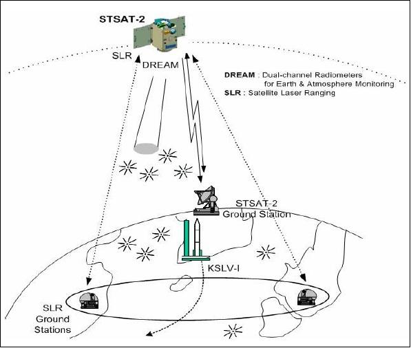
• Provision of Earth observation by acquiring brightness temperatures and water vapor in the microwave region in 2 channels. This requires the development of a radiometer, namely DREAM (Dual-channel Radiometers for Earth and Atmosphere Monitoring), the primary payload of the spacecraft.
• Development of SLR (Satellite Laser Ranging) technologies, with international tracking cooperation, for POD (Precise Orbit Determination) techniques of STSat-2 and future Korean spacecraft.
• Introduction of advanced spacecraft subsystem development technologies involving such items as: a) a stable operational spacecraft environment (thermally, mechanically, electrically, and radiation-resistant) in its orbit, b) a capability to provide a high-precision spacecraft attitude and agility, c) use of a PPT (Pulsed Plasma Thruster) for an orbit transfer experiment, d) provision of a high-rate downlink experiment (10 Mbit/s) in X-band.
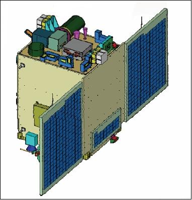
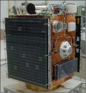
Spacecraft
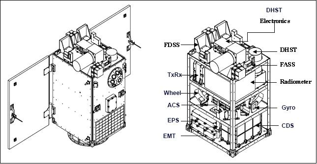
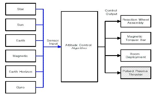
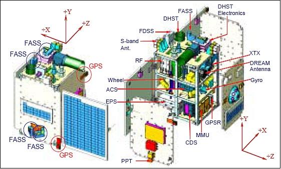
The spacecraft development is based on technologies flown on the KITSat series and of course STSat-1. The spacecraft is being designed and manufactured by SaTReC (Satellite Research Center) of KAIST (Korea Advanced Institute of Science and Technology). The microsatellite is three-axis stabilized. The spacecraft bus is 3-axis stabilized featuring a box structure (frame type) using CFRP Carbon Fiber Reinforced Plastic) with two deployable solar panels. The internal volume of the S/C features 2 equipment platforms. Electric power of 160 W (EOL) is provided by triple-junction solar cells; the battery has a capacity of 7 Ah. Attitude is sensed by coarse and 4 fine analog sun sensors, a FDSS (Fine Digital Sun Sensor), DHST (Dual-Head Star Tracker), 2 magnetometers, and 4 fiber optic gyros (FOG) for rate measurements. Actuation is provided by a reaction wheel array and a magnetorquer for bias momentum unloading. The pointing accuracy is 0.15º. A GPS receiver provides real-time orbit parameters. The spacecraft design life is 2 years. 4) 5) 6)
RF Communications
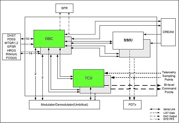
An onboard storage capacity of 4 Gbit is provided. S-band communications for TT&C support at 1.2 or 9.6 kbit/s in uplink and 9.6 or 38.4 kbit/s in downlink (FSK modulation). In addition, there is an X-band downlink at 10 Mbit/s (QPSK modulation) for data dumps during contact periods.
Orbit
An elliptical orbit is selected with a perigee of 300 km and an apogee of 1,500 km, inclination = 80º, period = 103 minutes (eccentricity of 0.082435).
Spacecraft mass, size | ~100 kg, 65 cm x 62 cm x 93 cm |
Spacecraft power | 150 W (EOL) using GaInP2/GaAs/Ge solar cells (triple junction) |
Spacecraft design life | 2 years |
Attitude control | 3-axis stabilization |
RF communication | S-band for TT&C data, uplink of 1.2 or 9.6 kbit/s, downlink of 9.6 or 38.4 kbit/s |
OBC | Power PC603e, 25 MHz |
Launch
A launch of STSat-2 took place on Aug. 25. 2009 on the first Korean-developed launch system KSLV-1 (Korean Satellite Launch Vehicle-1), representing the first flight from the Naro Space Center in Ko-heung, located on the southern coast of Korea (Launch site: long. = 127.54º E, latitude = 34.43º N, altitude = 107 m). Satellite laser ranging (SLR) is being used for validation of the launch vehicle's performance.
Unfortunately, a launch failure occurred on the maiden flight of KSLV-1. During the launch, half of the payload's fairing failed to separate, and as a result the rocket was thrown off course. While the first and second stage rockets of the KSLV-1 separated as planned after liftoff, one of the two fairings covering the satellite did not fall off properly. The satellite did not reach a stable orbit. 7) 8)
The KSLV-1 development is a joint effort between KARI and KhSC (Khrunichev State Research and Production Space Center) of Moscow; a cooperation agreement was signed in Oct. 2004. KhSC will build the 1st KSLV-1 stage (of Angara heritage) while the 2nd stage is to be designed and produced in South Korea.
Sensor/Experiment Complement
DREAM (Dual-channel Radiometers for Earth and Atmosphere Monitoring)
DREAM is the main payload of STSat-2 and the first spaceborne radiometer in the Space Program of Korea. The instrument is being developed in a joint project by the Sensor System Laboratory (SSL) at GIST (Gwangju Institute of Science and Technology), Gwangju, Korea, and by CSSAR (Center for Space Science and Applied Research), Beijing, China. The overall project objective is the development of instrument microwave radiometer technology and the analysis and interpretation of the data for a variety of applications (study of the physical parameters such as precipitation, water vapor and cloud liquid water). 9) 10) 11) 12) 13) 14)
DREAM development is being funded by MOST (Ministry of Science and Technology), Korea, and by KOSEF (Korean Science and Engineering Foundation).
Parameter | 23.8 GHz Receiver | 37 GHz Receiver |
Center frequency | 23.8 GHz | 37 GHz |
3 dB beamwidth of MA | 10.6º | 9.8º |
Sidelobe level of MA | < - 28 dB | < - 22 dB |
Beam efficiency of MA | > 98% | > 98% |
IF Bandwidth | 340 MHz | 510 MHz |
Noise figure | < 4.8 dB | < 6.4 dB |
Integration time | 204 ms | 208 ms |
Sampling time | 200 ms | 200 ms |
Dynamic range | 3-340 K | 3-340 K |
Radiometric accuracy | < 2.0 K | < 2.0 K |
Radiometric sensitivity | < 0.2 K | < 0.2 K |
Linearity | > 0.99 | > 0.99 |
Look direction | Nadir | |
Antenna polarization | Linear polarization | |
Swath width | 52.5 - 262 km (perigee and apogee) | |
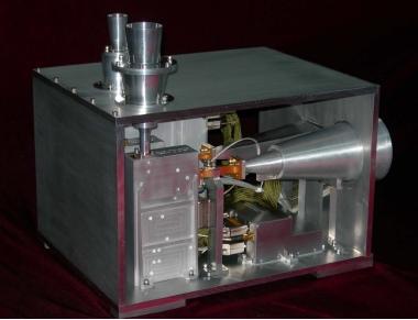
Instrument size | 33 cm x 27 cm x 20 cm | |
Instrument mass, power | 15 kg, 20 W | |
DREAM measures the brightness temperature of the Earth's surface and atmosphere without a capability of antenna scanning, due to the instrument volume and mass limitations; hence, the swath width corresponds to the footprint size. However, the elliptic orbit of the spacecraft varies the swath/footprint extremities from 52.5 km to 262 km at perigee and apogee, respectively.
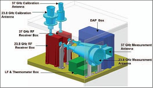
The main elements/subsystems of the instrument are: 4 antennas, 2 microwave receivers at 23.8 and at 37 GHz, DAPS (Data Acquisition/Processing System), EPS (Electrical Power System), and LF unit/thermometer.
The antennas are comprised of two measurement antennas (MA) and two calibration antennas (CA). The measurement antennas are of the type corrugated horn antennas with low side-lobe and high main-beam efficiency, with 3 dB beamwidths of 10º. The calibration antennas are of the type horn antennas with 3 dB beamwidths of 20º. The observation antennas are pointed to nadir while the calibration antennas are pointed to the deep space.
The radiometers are of the total-power type, achieving high sensitivity due to the fact that these radiometers are observing the target during the entire integration time. The radiometers feature a heterodyne receiver and operate in double-sideband mode. In DREAM, the radiometer receivers are divided into two units (boxes) because of the limited space conditions. The RF receiver box includes the RF switch, RF LNA, mixer, local oscillator, IF amplifier, and IF BPF. The LF box includes detector, LF amplifier, and integrator.
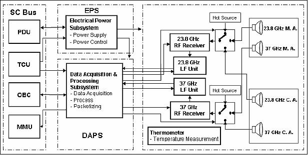
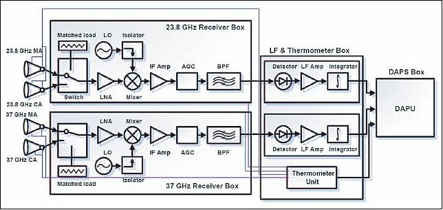
Instrument calibration: Two reference sources are used for the calibration purpose. One is the cold source using the space background emission received by the calibration antennas. A matched load, mounted in the front-end of the receiver, is being used as the hot temperature reference source. With these references, the radiometric calibration will be conducted periodically in orbit. In DREAM, the period including two calibrations and observations is 10.2 seconds and each calibration is executed every 9 seconds.
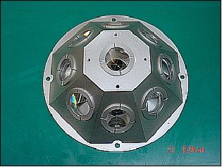
LRA (Laser Retroreflector Array)
LRA was developed through an international collaboration between SaTReC/KAIST, South Korea and the Shanghai Astronomical Observatory, China. 15) 16)
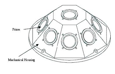
The objective is to provide a passive SLR (Satellite Laser Ranging) capability for orbit tracking from laser ranging stations in the ground segment. LRA consists of an array of 9 retroreflectors. Each prism corner cube is 30 mm (clear aperture) cylinder of fused silica containing a three-surface corner mirror. The corner cubes are symmetrically mounted on a hemispherical surface with a nadir-pointing corner cube in the center, surrounded by an angled ring (40º) of 8 corner cubes. The prisms reflect short laser pulses back to the transmitting ground station in a FOV of 360º in azimuth and 60º in elevation around the perpendicular to the centered corner cube. The diameter of the assembly is 200 mm.
DHST (Dual Head Star Tracker)
DHST is a technology demonstration experiment employing dual-head optics (in different directions), sharing the same focal plane, detection, and readout electronics of the imagery.
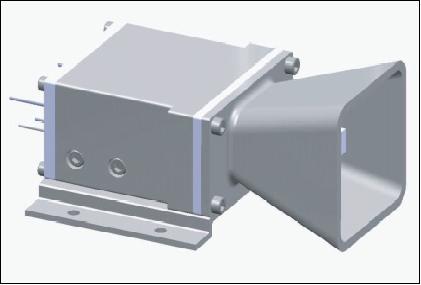
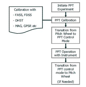
PPT (Pulsed Plasma Thruster)
PPT is a technology demonstration experiment developed by SaTReC/KAIST (Satellite Technology Research Center/Korea Advanced Institute of Science and Technology). The PPT is capable of producing an impulse of 20 µNs with a specific impulse of 800 s. The objective of the PPT is to enhance attitude control on the spacecraft [the attitude is mainly controlled by RWAs (Reaction Wheel Assemblies)]. 17) 18)
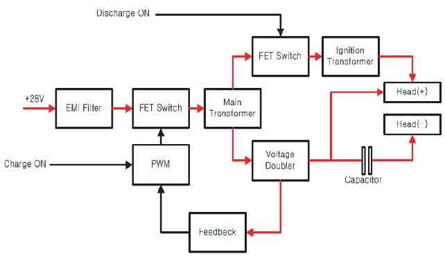
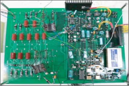
The PPT consists of a PPU (Power Processing Unit), a capacitor bank (~ 2 µF), and a thruster head consisting of a feeding spring and a nozzle. The PPT technique generates plasma by ablating a solid block of spring-fed Teflon. Power from the spacecraft EPS (Electrical Power Subsystem) is provided to the PPU to produce an appropriate power for the PPT of ~ +1500V. The PPU is illustrated in Figures 14 and 15. A capacitor (size: 94 mm x 96 mm x 32 mm) is being used to produce an appropriate torque to the spacecraft and to store electrical energy.
The single PPT device (generally, 6 PPTs would be needed for complete attitude control) is mounted on the pitch axis to unload the spacecraft momentum. The baseline on-orbit validation plan of the PPT experiment is using the four RWAs (after some instruments have fulfilled their minimum mission requirements) as shown in Figure .
FDSS (Fine Digital Sun Sensor)
FDSS is a technology demonstration experiment. The lens-less FDSS employs a CMOS CCD detector array with a FOV of 20º x 20º. A pointing accuracy of 0.03º (2 axes, 2σ) is provided. The FDSS mass is < 1 kg, power < 1.5 W, size: 150 mm x 150 mm x 160 mm. 19)
References
1) E.-S. Sim, S.-H. Lee, J.-O. Park, “The STSat-2 Program of Korea: A Program on Space Science and Technology Demonstration,” Proceedings of WSANE 2005 (Workshop for Space, Aeronautical and Navigational Electronics 2005), KARI, Daejeon, Korea, March 3-5, 2005, pp. 103-107
2) J.-T. Lim, M.-R. Nam, K.-S. Ryu, K.-M. Tahk, S.-H. Rhee, K.-H. Kim, “Exploring Space on a Small Satellite, STSat-2: A Test Bed for New Technologies,” Proceedings of AIAA/USU Conference on Small Satellites, Logan UT, Aug. 11-14, 2003, SSC03-VI-5
3) B.-S. Kim, E.-S. Sim, G. W. Morgenthaler, “The STSat-2 Program to Demonstrate Space Science and Technology,” Proceedings of the 56th IAC 2005, Fukuoda, Japan, Oct. 17-21, 2005, IAC-05-B5.1.05
4) Space Programs in Korea, 2006, URL: http://www.aprsaf.org/data/aprsaf13_data/7_Space%20Program%20Korea_KARI_final_030day1.pdf
5) Tae Seong Jang, “Spacecraft Structures & Mechanisms,” April 10, 2007, URL: http://csplab.kaist.ac.kr/lecture/SatRec2007/lecture_notes/EE807_070410.pdf
6) Sang-Hyun Lee, Kyunghee Kim, Jun Ho Lee, Jonghan Jin, Noh Hoon Myung, “Laser Retroreflector Array Development for STSAT-2,” 16th International Workshop on Laser Ranging, October 13-17, 2009, Poznan, Poland, URL: http://cddis.gsfc.nasa.gov/lw16/docs/presentations/tar_8_Lee.pdf
7) “S. Korean satellite lost shortly after launch: gov't,” Aug. 26, 2009, URL: http://english.yonhapnews.co.kr/techscience/2009/08/26/15/0601000000AEN200HT...
8) “Historic South Korean satellite launch fails,” Spaceflight Now, Aug. 25, 2009, URL: http://www.spaceflightnow.com/news/n0908/25kslv/
9) Sung-Hyun Kim, Ho-Jin Lee, Nam-Won Moon, Jin-Taek Seong, Hoon Wi, Eun-Sup Sim, De-Hai Zhang, Jing-Shan Jiang, Yong-Hoon Kim, “Radiometric Calibration of Korean Spaceborne Microwave Radiometer DREAM,” Proceedings of IGARSS 2008 (IEEE International Geoscience & Remote Sensing Symposium), Boston, MA, USA, July 6-11, 2008
10) H.-J. Lee, S.-H. Kim, N.-W. Moon, J.-T. Seong, Y.-H. Kim, D.-H. Zhang, J.-S. Jiang, “Hardware Specification and System Performance of Dual-channel Radiometers for Earth and Atmosphere Monitoring (DREAM) Flight Model,” Proceedings of IGARSS 2007 (International Geoscience and Remote Sensing Symposium), Barcelona, Spain, July 23-27, 2007
11) S.-H. Kim, Ho-Jin Lee, Seok-Hun Yun, Jin-Mi Jeong, Chun-Sik Chae, Manoj Kumar Singh, Jong-Oh Park, Eun-Sup Sim, De-Hai Zhang, Jing-Shan Jiang, Yong-Hoon Kim, “Design and Performance of Dual-channel Radiometers for Earth and Atmosphere Monitoring (DREAM) Protoflight Model,” Proceedings of IGARSS 2006 and 27th Canadian Symposium on Remote Sensing, Denver CO, USA, July 31-Aug. 4, 2006
12) S.-H. Kim, De-Hai Zhang, Ho-Jin Lee, H. Park, S.-H. Yun, C.-S. Chae, E.-S. Sim, J.-S. Jiang, Y.-H. Kim, “Korean Spaceborne Microwave Radiometer on STSat-2: Dual-channel Radiometers for Earth and Atmosphere Monitoring (DREAM),” Proceedings of IGARSS 2005, Seoul, Korea, July 25-29, 2005
13) S.-H. Kim; H.-J. Lee; C.-S. Chae; H. Park; S.-H. Yun; J.-O. Park; S.-H. Lee; E.-S. Sim; De-Hai Zhang; J.-S. Jiang; Y.-H. Kim, “Dual-channel radiometers for Earth and atmosphere monitoring (DREAM) on micro satellite STSAT-2,” Proceedings of APMC (Asia Pacific Microwave Conference) 2005, Vol. 1, Dec. 4-7, 2005, Suzhou, China
14) Sung-Hyun Kim, Ho-Jin Lee, Seok-Hun Yun, Chun-Sik Chae, Hyuk Park, Yong-Hoon Kim, “Design of High Sensitive Spaceborne Microwave Radiometer DREAM on STSat-2,” ISRS 2005 (International Symposium on Remote Sensing), Jeju, Korea, Oct. 12-14,2005
15) Jun Ho Lee, S. B. Kim, K. H. Kim, S. H. Lee, Y. J. Im, Y. Fumin, C. Wanzhen, “Korea's First Satellite for Satellite Laser Ranging,” URL: http://cddis.nasa.gov/lw14/docs/presnts/ops3_jlp.pdf
16) S.-B. Kim, K.-Hee Kim, S.-H. Lee, Y.-J. Im, Y. Fumin, C. Wanzhen, “Korea's first satellite for satellite laser ranging,” Acta Astronautica, Vol. 56, Issue 5, March 2005, pp. 547-553
17) G.-H. Shin, M.-R. Nam, W.-H Cha, J.-T. Lim, “Development of the Pulsed Plasma Thruster (PPT) for Science and Technology Satellite-2 (STSat-2),” ICCAS 2005, June 2-5, 2005, Kintex, Gyeonggi-Do, Korea
18) Goo-Hwan Shin, Gun-Soo Shin, Myeong-Ryong Nam, Kyung-In Kang, Jong-Tae Lim, “High Voltage DC-DC Converter of Pulsed Plasma Thruster for Science and Technology Satellite-2 (STSAT-2),” Proceedings of the 6th International Conference on Power Electronics and Drives Systems (PEDS 2005), Volume 2, Nov. 28- Dec. 1, 2005, Kuala Lumpur, Malaysia, pp. 926 - 931
19) S.-H. Rhee, T.-S. Jang, C.-W. Ryu, M.-R. Nam, J. Lyou, “Fine Digital Sun Sensor(FDSS) Design and Analysis for STSat-2,” ICCAS 2005 (International Conference on Control, Automation and Systems), June 2-5, 2005, Kintex, Gyeonggi-Do, Korea
The information compiled and edited in this article was provided by Herbert J. Kramer from his documentation of: ”Observation of the Earth and Its Environment: Survey of Missions and Sensors” (Springer Verlag) as well as many other sources after the publication of the 4th edition in 2002. - Comments and corrections to this article are always welcome for further updates (eoportal@symbios.space).