SVOM (Space Variable Objects Monitor) Mission
Non-EO
CNES
CNSA
Planned
Quick facts
Overview
| Mission type | Non-EO |
| Agency | CNES, CNSA |
| Mission status | Planned |
SVOM (Space Variable Objects Monitor) Mission
Spacecraft Launch The SVOM System Sensor Complement Ground Segment References
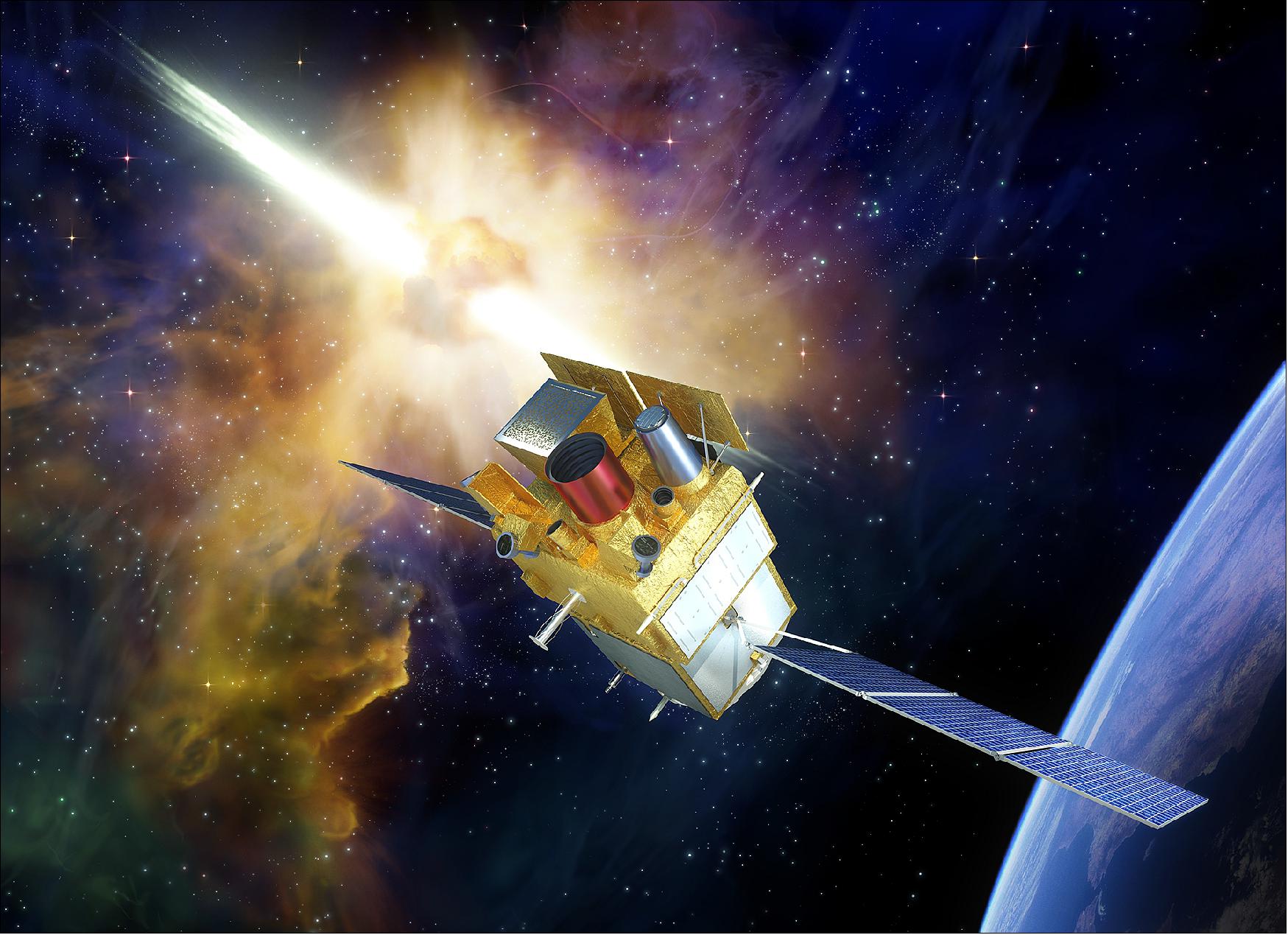
SVOM is a joint Chinese-French satellite observatory dedicated to the study of GRBs (Gamma-Ray Bursts) in the next decade. The goal of the mission is to study the most powerful explosions in the universe out to the era of the first generation of stars, SVOM will locate hundreds of GRBs signifying the deaths of massive stars or with the merging of two compact stars. In both cases the end product of the explosion is a black hole or a young magnetar surrounded by a torus of matter that is quickly accreted onto the compact object (in seconds), releasing huge amounts of energy in two transient relativistic jets. When one of the jets is pointed to the Earth, we see a bright high energy transient followed by a quickly fading afterglow. 1) 2) 3) 4) 5) 6) 7)
The study of GRBs sheds light on several key questions of modern astrophysics, like the physics at work in astrophysical relativistic jets, the end of life of massive stars and the birth of stellar mass black holes, the history of massive star formation over the ages, the history of the reionization of the universe and of the chemical enrichment of galaxies, etc. Some of these questions are directly connected with the study of GRBs, while other use them as lighthouses illuminating the remote regions of our universe, out to redshift z ≥10. The detection of GRBs will thus remain of high priority in the coming years.
The objective of the SVOM mission is to continue the exploration of the transient universe with a set of space-based multi-wavelength instruments, following the way opened by Swift. SVOM is a space mission developed in cooperation between the CNSA (Chinese National Space Agency), CAS (Chinese Academy of Science) and the French Space Agency (CNES). The mission features a medium size satellite, a set of space and ground instruments designed to detect, locate and follow-up GRBs of all kinds, a anti-Sun pointing strategy allowing the immediate follow-up of SVOM GRBs with ground based telescopes, and a fast data transmission to the ground.
The Chinese and French laboratories involved in the mission are : NAOC at Beijing, IHEP at Beijing, XIOPM at Xi’an, SECM at Shanghai, CEA-Irfu at Saclay, IRAP at Toulouse, APC at Paris and LAM at Marseille. In addition, MPE of Garching, Germany and the University of Leicester, UK, are contributing to the mission. The launch of the satellite by a Chinese Long March rocket is scheduled for the end of 2021 and the minimum lifetime of the mission is 3 years.
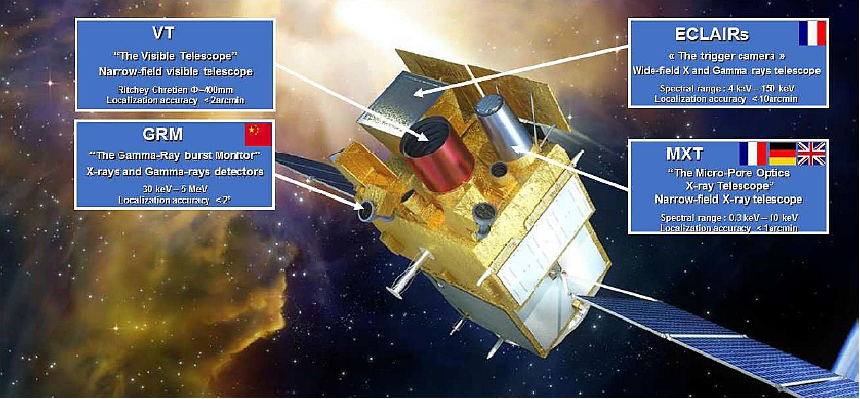
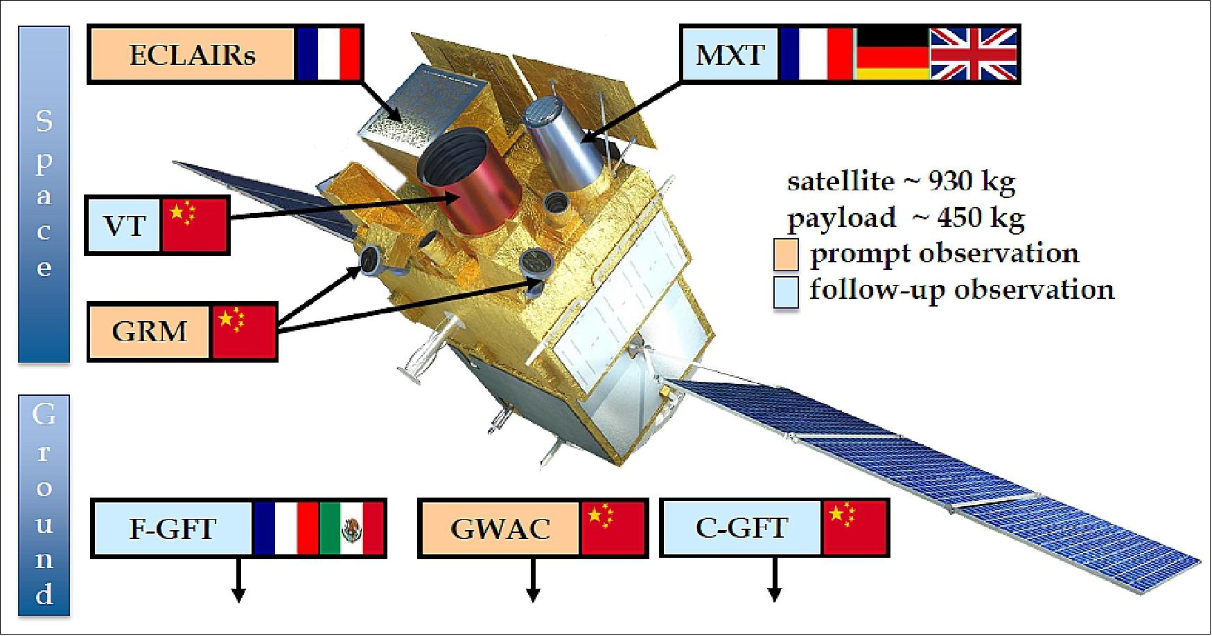
The satellite carries two wide field high energy instruments: a coded-mask gamma-ray imager called ECLAIRs, and a gamma-ray spectrometer called GRM (Gamma Ray Monitor), and two narrow field telescopes that can measure the evolution of the afterglow after a slew of the satellite: an X-ray telescope called MXT (Micropore X-ray Telescope)and an optical telescope called VT(Visible Telescope). The ground segment includes additional instrumentation: GWAC (Ground Wide Angle optical Camera) monitoring the field of view of ECLAIRs in real time during part of the orbit, and two 1 m class robotic GFTs (Ground Follow-up Telescopes).
SVOM has some unique features: an energy threshold of ECLAIRs at 4 keV enabling the detection of faint soft GRBs (e.g. XRFs and high-z GRBs); a good match in sensitivity between the X-ray and optical space telescopes which permits the detection of most GRB afterglows with both telescopes; and a set of optical instruments on the ground dedicated to the mission. The mission has recently been confirmed by the Chinese and French space agencies for a launch in 2021, and it has entered in an active phase of construction.
The main science goal of SVOM is the study of cosmic transients detected in hard X-rays and in the optical domain. While the mission has been designed for the study of GRBs (Gamma Ray Bursts), it is also well suited for the study of other types of high-energy transients like TDEs (Tidal Disruption Events), AGNs (Active Galactic Nuclei), or galactic X-ray binaries and magnetars. For these types of sources, SVOM is both a "discovery machine", with wide field instruments that survey a significant fraction of the sky [(ECLAIRs, GRM (Gamma Ray Monitor) and GWAC (Ground Wide Angle Camera)], and a "follow-up machine", with fast pointing telescopes in space and on the ground (MXT (Microchannel X-ray Telescope), VT, and GFTs) that provide a multi-wavelength follow-up of different kinds of sources, with good sensitivity and a high duty cycle. The follow-up can be triggered by the satellite itself or from the ground, upon reception of a request for ToO (Target of Opportunity) observations.
SVOM collaboration: CAS, CNSA, NAOC Beijing, IHEP Beijing, NSSC Beijing, SECM Shanghai, CNES, LAMMarseille, IRAP Toulouse, GEPIMeudon, IAP Paris, LAL Orsay, CPPMMarseille, APC Paris, LUPM Montpellier, University of Leicester, MPE Garching, UNAM Mexico.
Background
Forty years after its discovery, the Gamma-Ray Burst (GRB) phenomenon is not yet completely understood . The cosmological nature of these transient sources of gamma-rays has been established, and their association with explosions of massive stars (>30 Msun) is a scenario that reproduces most observations, at least for long duration GRB. They have been detected up to redshift 8.2, with the possibility to investigate the early Universe (star formation history, re-ionization era), and to derive cosmological parameters. Conversely for short duration GRB, mostly described by coalescences of two compact objects (black holes, neutron stars or white dwarfs), the situation is less consensual and lacks a good sample of afterglow observations. Open questions concern the physical processes during the prompt phase (particle acceleration, radiation), the GRB classification, the characterization of GRB host galaxies and progenitors, as well as fundamental physics issues like Lorentz invariance, the origin of cosmic rays and gravitational waves. 8)
Time-Domain Astrophysics - The Discovery Space After Swift
Astronomy is truly undergoing a revolution in terms of our ability to monitor the time-variability of the Universe in a continuous way using new facilities coupled with fast computers. The opening up of the temporal domain is transforming our knowledge of how the Universe evolves, particularly for objects which are undergoing explosive change, such as a supernova or a Gamma-ray Burst (GRB). These explosive events can release enormous amounts of power both in electromagnetic radiation and in non-electromagnetic forms such as neutrinos and gravitational-waves and test our understanding of the laws of physics under the most extreme conditions.
Observing facilities which are currently on-line enable the sky to be monitored fairly continuously in real-time over large areas and across the electromagnetic spectrum, capturing the temporal behavior of the Universe in a way previously unattainable. Examples facilities include the LOFAR radio telescope, the Pan-STARRs optical facility and the Swift and Fermi high-energy satellites. Non-electromagnetic facilities are also now observing, particularly the Advanced LIGO-VIRGO gravitational-wave observatory, which recently found its first source, and the IceCube neutrino experiment. The data from all these facilities have already opened up the temporal domain, but are just a foretaste of what is to come.
Many of the previously developed theories have come under intense strain by new observational results, such as the highly variable emission seen at late times in GRBs, the discovery of extremely luminous supernovae and the unexplained fast radio bursts. Theoretical models predict a variety of exotic explosions and stellar mergers, together with their multiple signatures across the electromagnetic spectrum. Theory also predicts that some will be accompanied by gravitational wave, neutrino and high-energy particle emission. The provision of SVOM in the next decade will coincide with the multi-messenger era and will provide a critical element of the era of time-domain astronomy both by finding transients and by following-up those from other facilities.
In the period when SVOM will fly, the number of transients found will increase by several orders of magnitude as even more powerful facilities come on-line, in particular the LSST (Large Synoptic Survey Telescope), 9) and the SKA (Square Kilometre Array). 10)The sheer grasp of the new facilities, which will produce thousands of alerts per day from variable or transient sources, mean we will require super-computers to process the data in real-time and smart algorithms to broker which transients to focus on with follow-up facilities. The importance of the temporal domain has been recognized in recent reports by the Chinese Space and Technology Roadmap, 11) the European Union ASTRONET group 12) and the USA National Research Council Decadal Survey (Committee for a Decadal Survey of Astronomy and Astrophysics, 2010). 13)
The Astronomical Panorama in 2020
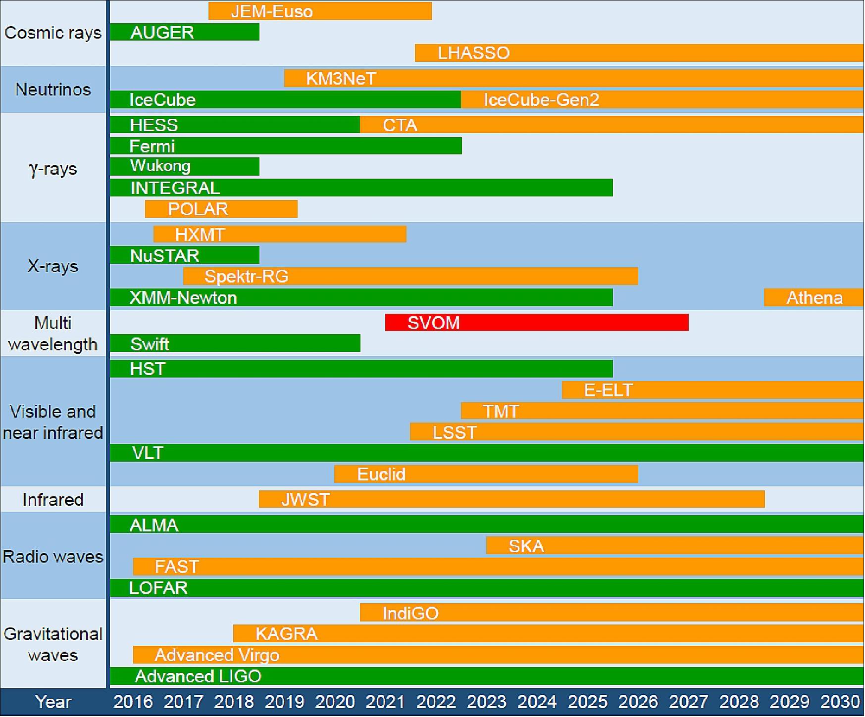
The astronomical panorama of the next decade will be shaped by new instruments developed to address various outstanding questions raised by present day astrophysics. This panorama encompasses large radio, infrared, visible and gamma-ray telescopes, advanced gravitational wave interferometers and neutrino detectors of the km3 class (Figure 1), as well as simulations with powerful computers. These instruments will revolutionize our understanding of astrophysics in fields as diverse as the first ages and the reionization of the universe, the nature of the dark universe (dark matter and dark energy), the demography and role of black holes, exoplanets and planetary formation, and fundamental physical processes. Young fields, like Time Domain Astronomy and Multi-Messenger Astrophysics are also expected to grow very fast, bringing new discoveries (Ref. 6).
Scientific Objectives
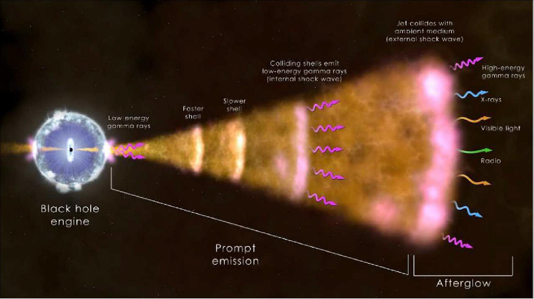
The GRBs are short and intense flashes of X-rays and gamma-rays lasting from few milliseconds to hundreds of seconds, uniformly distributed in the sky. Produced by transient relativistic jets, GRBs are accelerated by newly formed black holes after the collapse of the core of a massive star or the coalescence of two neutron stars.
The prompt emission is followed by a multiwavelength afterglow emission which decays on a few days to weeks in X-rays and visible, and up to several years in radio. These transient emissions give crucial information on both their progenitors and the physical processes involved in the jets. Considering their cosmological distances and their incredible brightness, GRBs are effective tools to probe the early Universe but also to explore some of the major issues of modern astrophysics. 14)
Mission Concept
Overall Scenario
SVOM will provide a service to the community at large through the fast delivery of GRB position, of the main properties of the prompt emission, and of the magnitude of the early afterglow. In addition, it will guarantee a high scientific return for the SVOM partners, with the details of the prompt emission in a broad range of wavelengths, the multi-band photometry of the early afterglow, and the unique possibility to catch the GRB prompt visible emission, a uniform sample of visible afterglow light curves with long and frequent time coverage.
While GRBs will occupy a small fraction of the SVOM observing time (probably around 25%) the broad wavelength coverage and good sensitivity of the on-board instrumentation allows performing non GRB science on selected topics during the remaining time (earth environment studies, supernovae and galaxy observation, X-ray survey etc.).
The constraint applicable to the non GRB science is that the observation shall not impact the GRB detection and observation, except for some urgent observations with a very high priority that can be decided by the SVOM science group, for example after detection of an exceptional event by ground telescopes.
During the mission lifetime, any unpredictable event (i.e. GRB) or urgent observation request (i.e. ToO) can lead to interrupt the on-going observation sequence. The re-scheduling strategy of the SVOM mission shall allow the upmost versatility so that observations from Core, ToO or General programs can be satisfactorily achieved. 15)
Mission sub-programs - The mission is split into 4 sub-programs with Different Objectives:
a) The “Core Program” (CP) consists in the observation of GRB automatically triggered. These observations are by essence unpredictable and prevail over most of the other observation types. The science objectives of the Core Program are to permit the detection of all known types of GRBs, to provide fast reliable GRB position, to measure the broadband spectral shape of the prompt emission from visible to X-rays and to measure the temporal properties of the prompt emission.
b) The ToO (Targets of Opportunity) which respond to very specific and time-constrained needs from the scientific community. For instance, SVOM will bring information to complement gravitational wave experiments; the time and position of short GRBs provided by SVOM will improve the noise rejection capability of large gravitational wave detectors (advanced VIRGO and LIGO) which will search gravitational signals coincident with short GRBs.
c) The “General Program” (GP) during which known targets, identified beforehand, are observed one after another. Among the main astrophysical sources to be studied by the narrow field instruments (MXT and VT) AGNs, blazars, ULXs, and Cataclysmic Variables are the most promising ones. Such broadband observations will deliver unique information about the physics of the emission processes at work in those extreme objects. The observation schedule for the GP program is built up from pools of proposals resulting from an annual “Call for Obs” and covering the whole coming year.
d) In addition, there is a fourth sub-program dedicated to instrument calibrations to be regularly performed through the course of the mission.
Mission phases: In order to fulfill mission objectives, the operational scenario will evolve during the whole mission where 2 main phases have been defined:
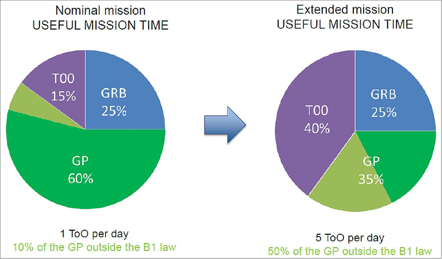
1) The nominal mission (NM) corresponds to the first 3 years of the SVOM lifetime; priority will be given to the core program (GRB detection)
2) The extended mission (EM) corresponds to the last 2 years of the SVOM lifetime; ToO and General Program observations will be enhanced.
Overall Architecture
The SVOM system has been designed to allow a high scientific return. For this reason, SVOM includes features like a pointing close to the anti-solar direction, the fast distribution of sub-arcminute positions, the full characterization of the prompt emission over a broad range of wavelengths, a dedicated follow-up at optical and Near Infra-Red wavelengths (NIR is especially needed for GRBs with redshift larger than 6), the quick computation and distribution of sub-arc second positions, and quick redshift estimates.
The overall system is composed of 3 main components, which include:
• the SVOM satellite consisting of a platform and a Payload Module (PLM)
• the SVOM Ground Segment consisting of Chinese Command Control Ground Segment (CCGS) and Mission Science Ground Segment (MSGS) including a Chinese part (C-MSGS) and a French one (F-MSGS)
• the launcher and associated services.
Spacecraft
China will be responsible for the mission, launch, satellite and operations and will share responsibility with France for design and construction of the instruments and the ground segment.
SVOM satellite is a medium size class; its mass is 950 kg, its power 800 W and the overall size is within an envelope of ∅ 2500 mm for 2800 mm height. The satellite is composed of a launcher adaptor, a bus platform and the PLM (Payload Module).
The platform is providing the support functions for on-orbit operations, including electrical power, command and data handling, telecommunications, thermal control, propulsion/orbit maintenance, and primary structure.
The payload is based on a suite which includes a combination of 4 instruments on-board the satellite.
Pointing strategy: With such an orbit, a specific attitude law has been defined in order to avoid permanent known X sources such as galactic equator and Sco-X1. Moreover, routine pointing optimization may allow to put the satellite in steady and predictable thermal conditions, with the aim of reducing as much as possible thermal impacts induced by satellite rotations towards the GRBs.
Platform: The SVOM platform is designed to be compatible with various orbits (phased, sun synchronous, frozen and inertial orbits) with altitudes ranging from 500 km to 1500 km, for an orbital plane inclination contained between 20º and 145º. The platform provides a wide range of payload pointing capabilities (Earth and anti-Earth pointing, inertial pointing).
The platform is fully redundant. The use of highly integrated electronics favors mass and power minimization and enhances the reliability. The functions of the platform include:
• a centralized Avionics Subsystem, providing a high performance attitude control based on Star Trackers and Reaction Wheels, and ensuring the overall satellite management
• a fully redundant Telecommand and Telemetry Subsystem, relying on flight-proven S-band hardware
• a reliable EPS (Electrical Power Subsystem)
• a light and robust structure
• a simple and reliable TCS (Thermal Control Subsystem), mastering the thermal behavior of different areas of the satellite
• a propulsion subsystem can be used for LEOP (Launch and Early Orbit Phase) attitude acquisition, LEOP orbit adjust, debris avoidance, and long term station keeping.
Development Status
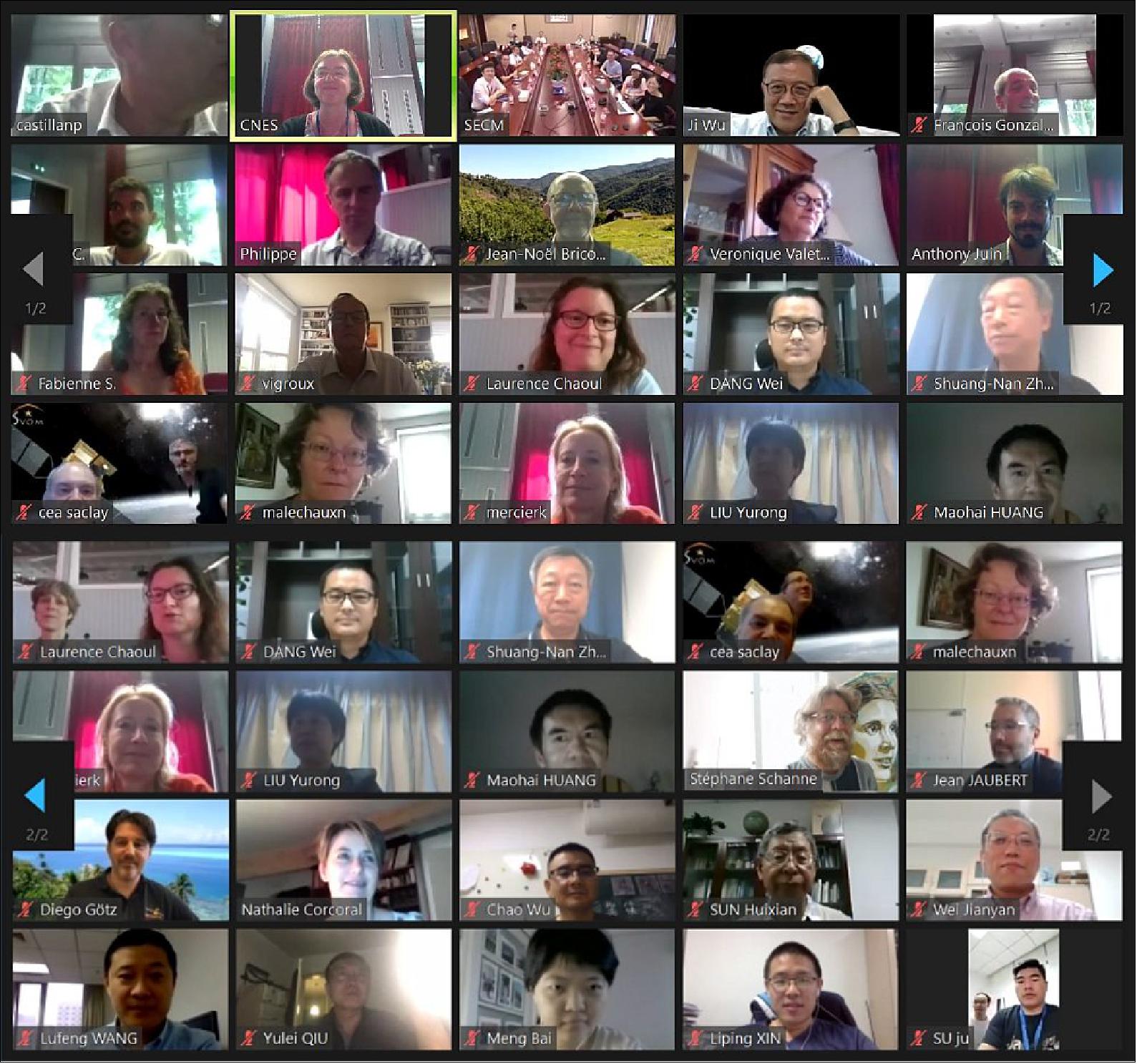
• July 2020: The end-of-Phase C Review (Critical Design Review) was held by videoconference from June 29 to July 10, 2020. — The SVOM project has been strongly impacted by the COVID-19 pandemic. At the end of January, the Chinese teams were confined and testing activities in Shanghai on the satellite qualification model were suspended. The Chinese teams gradually resumed work in March, but it was then the turn of the French teams to be confined.... Today, activities have resumed in all the laboratories but travel is still severely restricted and we do not expect any meetings before late autumn or even early next year. 16)
- The objective of this review was to verify that the system developed for the SVOM mission meets the scientific requirements of the mission. After two weeks of discussion, the review group did not identify any major problems. The impact of the pandemic on the project as a whole was assessed and a delay of 5 months on the initial planning was noted. The launch of SVOM is now scheduled for early June 2022.
- At the end of the meeting, the review group congratulated the SVOM team for the success of Phase C and encouraged them to continue in Phase D in the same spirit of cooperation.
• The Phase C kick-off of the SVOM project started in January 2017 17)
• In June 2016, the SVOM SRR (System Requirements Review) was completed.
• In October 2015, the University of Leicester has announced the signature of a contract to develop an innovative new type of X-ray mirror for a telescope to be flown on an orbiting observatory. 18)
• Phase B kick-off of the SVOM project started in September 2014.
Launch
The SVOM satellite mission (launch mass of ~930 kg) was scheduled to be launched in June 2022 with a Long March-2C vehicle from XLSC (Xichang Satellite Launch Center), China, however the launch has later been re-scheduled for mid-2023.
Orbit
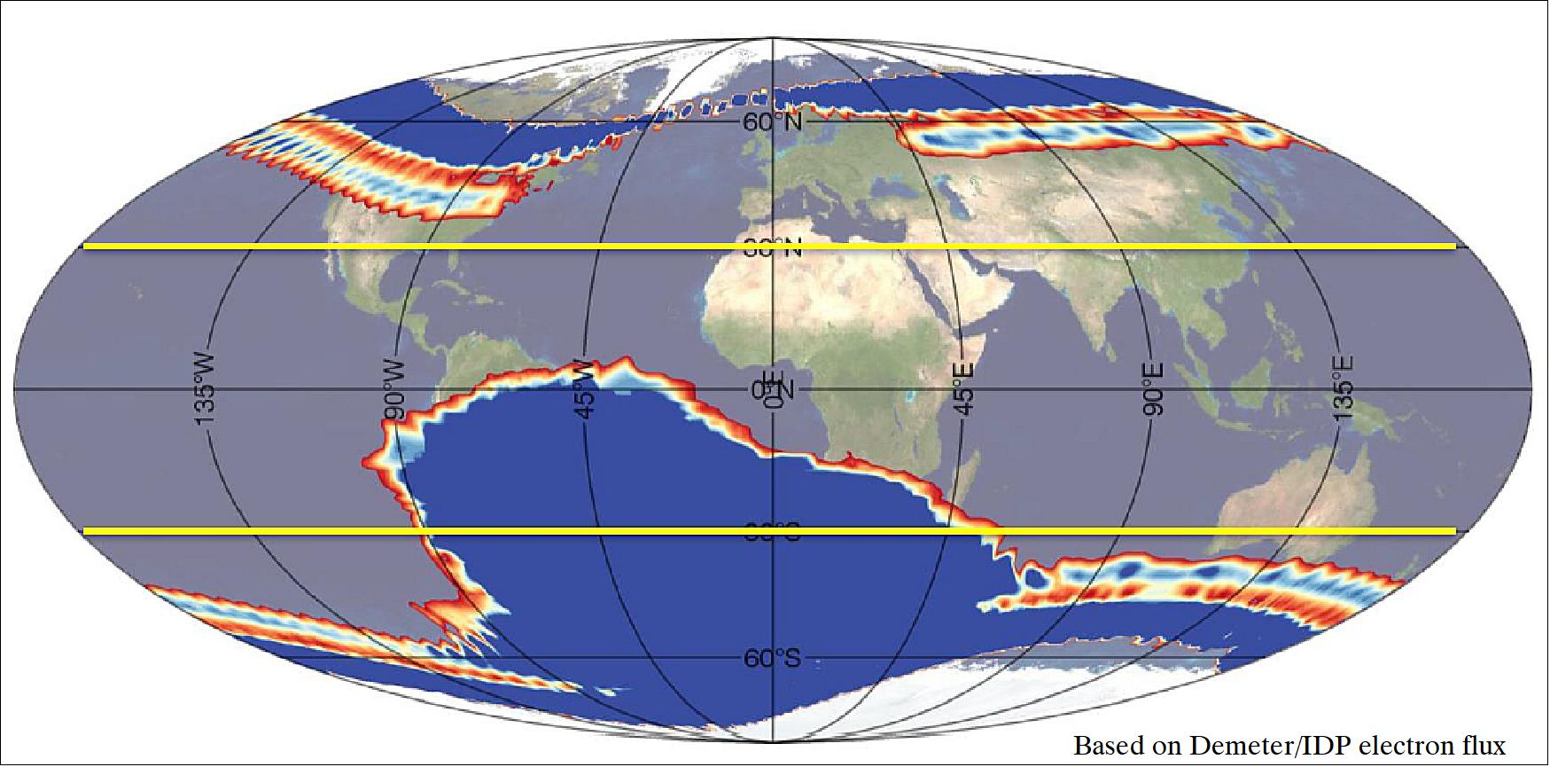
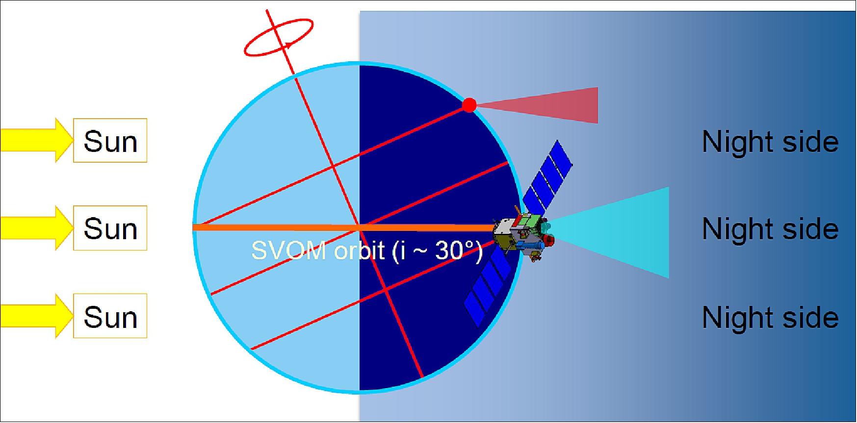
Near-circular orbit, altitude of ~625 km, inclination = 30º, period of ~86 minutes. With these parameters the satellite passes through the SAA (South Atlantic Anomaly) several times per day, inducing an overall dead-time of 13 to 17%.
The SVOM System
Pointing strategy: With a circular orbit of 625 km and an inclination of 30º, a specific attitude law has been defined in order to avoid permanent known X sources such as galactic equator and Sco-X1. Moreover, routine pointing optimization may allow to put the satellite in steady and predictable thermal conditions, with the aim of reducing as much as possible thermal impacts induced by satellite rotations towards the GRBs.
This pointing scenario leads the instruments to periodically face the Earth at each orbit, which reduces the overall observation time. Around the reference pointing of the attitude law, small maneuvers programmed from ground may be possible to look at different targets (from the General Program) or to revisit former GRBs to monitor the afterglow decay.
In order to facilitate measuring the redshifts of GRBs detected with ECLAIRs, the instruments of SVOM will be pointed close to the anti-solar direction. Most of the year the optical axis of the SVOM instruments will be pointed at about 45º from the anti-solar direction. This pointing is interleaved with avoidance periods during which the satellite passes away from the Sco X-1 source and the galactic plane. This strategy ensures that SVOM GRBs will be in the night hemisphere and quickly observable from the ground by large telescopes.
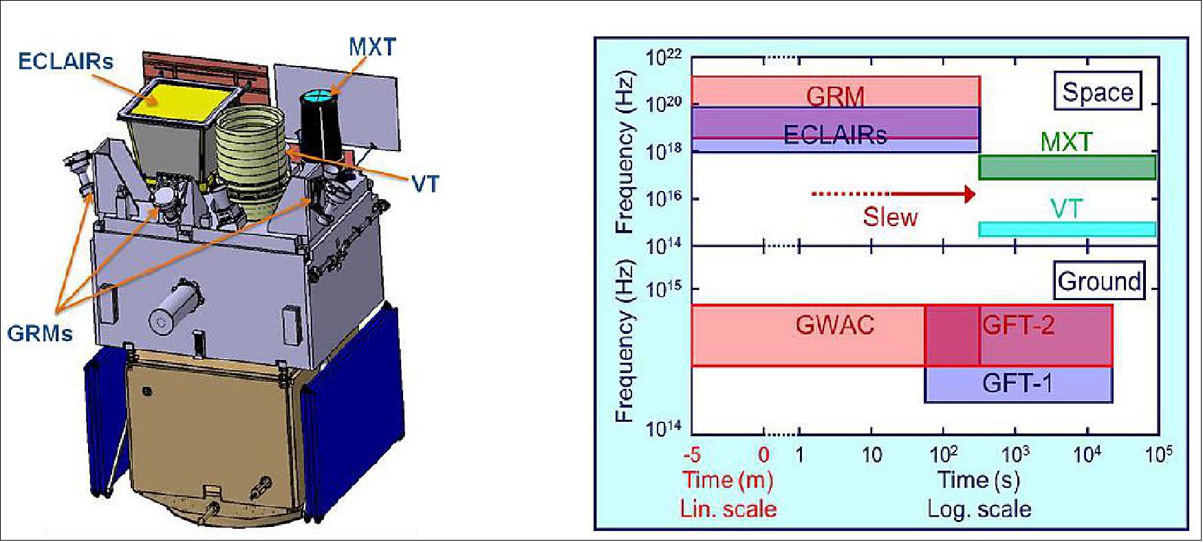
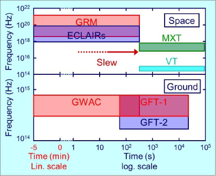
Observation strategy: With a multi-wavelength payload, the satellite will locate and measure the spectral parameters of the prompt emission with two wide-field instruments (GRM & ECLAIRs), while two narrow-field instruments in optical and X-ray bands (MXT & VT) will ensure the follow-up and refine the position of the GRBs.
In addition, the spaceborne observations will be complemented by observations with a set of distributed Ground Wide Angle Cameras (GWAC) together with the 2 Ground-based Follow-up Telescopes (GFT) with increased sensitivity in the optical band and extended coverage in the near infrared.
Figure 8 depicts the spectral coverage of the GRB prompt emission and its afterglow with SVOM instruments, as a function of time (the burst is detected at time t = 0). The upper panel refers to spaceborne instruments (GRM, ECLAIRs, MXT, VT), the lower panel to ground-based instruments (GWAC, C-GFT, FGFT).
GRB Follow-up: The goal of the follow-up is to participate actively in the ground observations of the afterglow using large ground based telescopes. Since large ground based telescopes usually run their own programs scheduled well in advance, the decision to quickly interrupt the ongoing observing program in order to point towards an optical afterglow localized by SVOM will depend on the GRB characteristics, mainly the raw estimate of its redshift (i.e. distance). The more distant the burst candidate is supposed to be, the more likely it is to be followed by large telescopes. SVOM also foresees to have direct links with some robotic telescopes selected among professional and efficient telescopes (i.e. TAROT, LCOGT).
Exceptional Events Follow-up: Target of Opportunities (ToO’s) are unplanned observations prepared and sent from the ground that interrupt the current observation program of the mission. ToO are decided by the PIs and/or ToO scientists.
In the case of MM (Multi-Messenger) events such as gravitational waves, a special ToO_MM scenario shall be performed within 12 hrs from acceptance by the PI’s. This scenario shall not be interrupted by any other observation. In order to cover the large error box of the source it is foreseen to perform a multiple tiles strategy. There should be 4 to 25 tiles with a maximum duration of 10 minutes each. The expected rate of the ToO_MM is one per week.
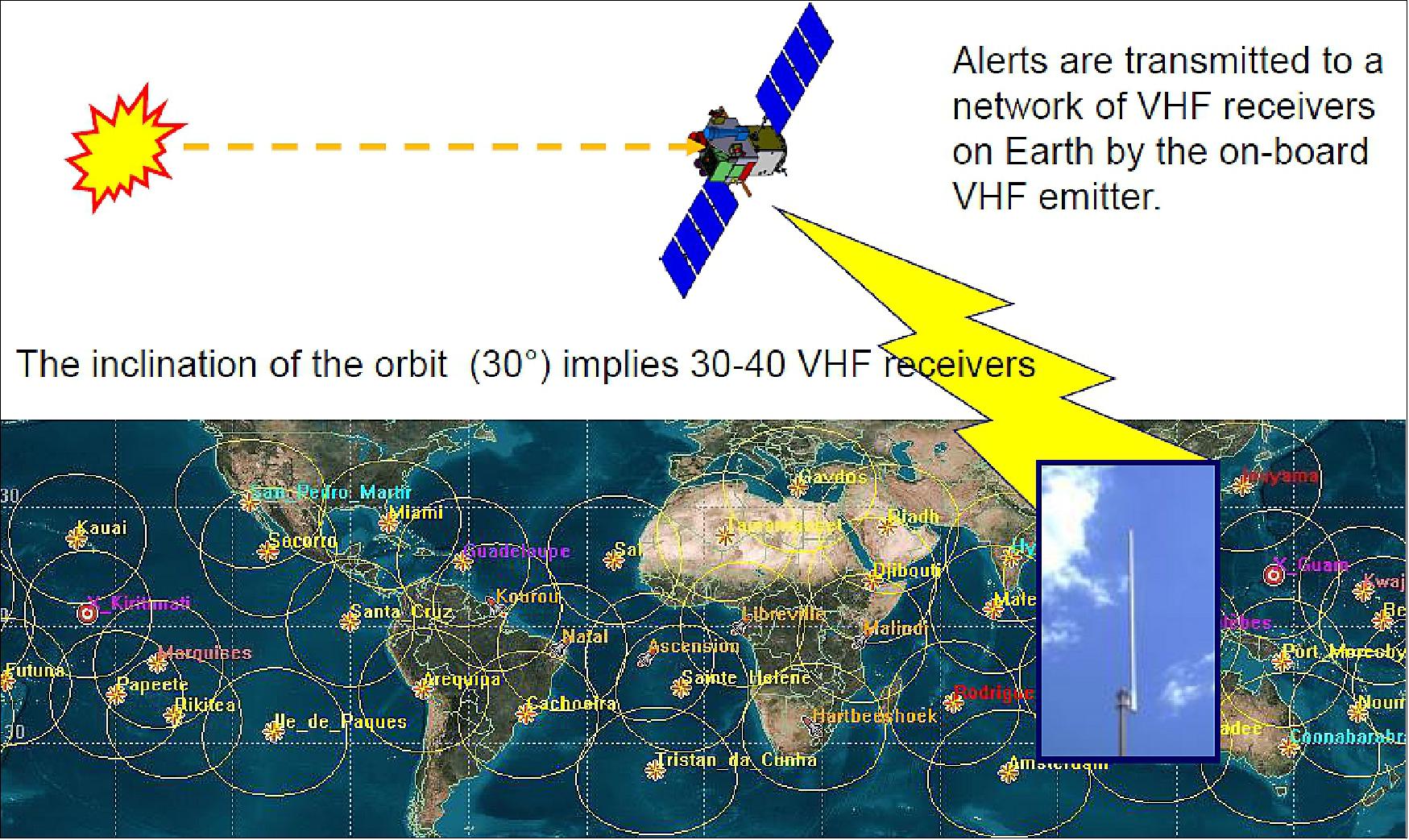
Alert distribution principle: The GFTs, GWAC, and more generally the robotic telescopes, shall be warned about the detection of a burst candidate in the first minutes following the onboard detection, which requires quasi-permanent visibility of satellite from the ground. The adopted solution consists in using a network of VHF antennas spread in low-to-middle Earth latitudes in order to cover the satellite ground track. The main purpose of the VHF alert network is to downlink in near real time the first alert generated on board the satellite. But the VHF network will also be used to downlink a subset of data to be analyzed on the ground at science centers, before the full data is available later through the X-band link.
In addition, the alert distribution aims at enabling large ground based telescopes (such as the VLT) to observe the optical afterglow of GRB detected by SVOM, in particular to determine accurately their redshift (i.e. distance).
Process: The alert is distributed in two steps via internet:
- Step 1: The on-board alerts together with a subset of data are received by one or more VHF antennas, according to the density of the ground network. Then, all alerts and data received by any individual VHF antenna are forwarded via internet to the FSC (French Science Center) which is the central reception node located at CEA/Saclay (France).
- Step 2: The VHF data set are analyzed promptly at the FSC under the supervision of Burst Advocates (BA’s), who are responsible for the distribution of alerts, the trigger validation and the requests for burst revisits or interruption of the automatic observing sequence on-board. The role of the Burst Advocate was first introduced in the framework of the NASA mission called Swift, in order to assure that for each GRB:
a) An accurate data analysis is promptly performed
b) Follow-up observations are well coordinated
c) Burst notifications and publications are produced.
Alerts: Once alerts and subset of data have been automatically processed at the FSC, they are distributed to a worldwide community, also using the internet. A network dedicated to the distribution of GRB alerts towards the scientific community already exists, the GCN network, which is maintained by NASA. The GCN (Gamma-ray Coordination Network) is operating since June 1993 and distributes three types of products to the GRB community:
i) Notices, containing the localization of GRBs detected by various spacecraft’s (Swift, HETE, INTEGRAL, etc.), some in real time while the burst is still bursting and others delayed due to telemetry downlink latency.
ii) Circulars, reporting about the follow-up observations made by ground and space-based optical, radio and x-ray observers. The main difference between a notice and a circular is that the circular is readable by humans.
iii) Reports, similar to circulars but summarizing in a single note all follow-up observations for a given burst.
Figure 14 depicts the SVOM VHF network as foreseen (currently under development at CNES). It is composed of 45 ground VHF stations located all around the Earth at latitudes between ±30°.The hosting sites have to be properly selected in order to insure a permanent link with the satellite. As much as possible, we plan to take benefit from already existing networks (i.e. DORIS) to install SVOM VHF ground stations.
The SVOM Attitude Law
Optimization of the SVOM Attitude Law
To favor the GRB detection by ECLAIRs
• avoidance of the the Sco X1source ( outside of the ECLAIRs FOV)
• avoidance of the Galactic Plane (± 10° for the ECLAIRs FOV )
To favor the redshift measurement on ground
• to favor the sky area observable from both Hawaii, Chile and the Canary
• SVOM points to areas near the equator (declination δ=0)
• To maintain a cold face for the satellite. Offset of 45° with respect to the antisolar direction
• Tolerance of 5° with respect to the nominal pointing
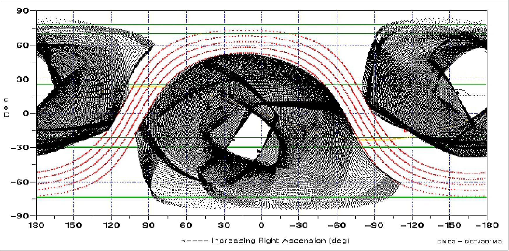
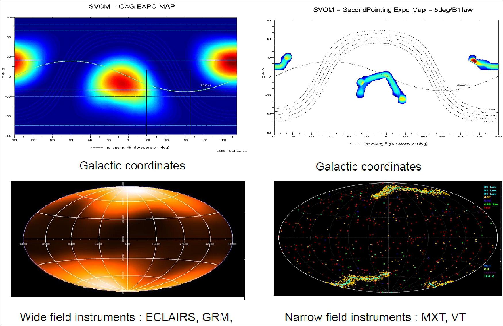
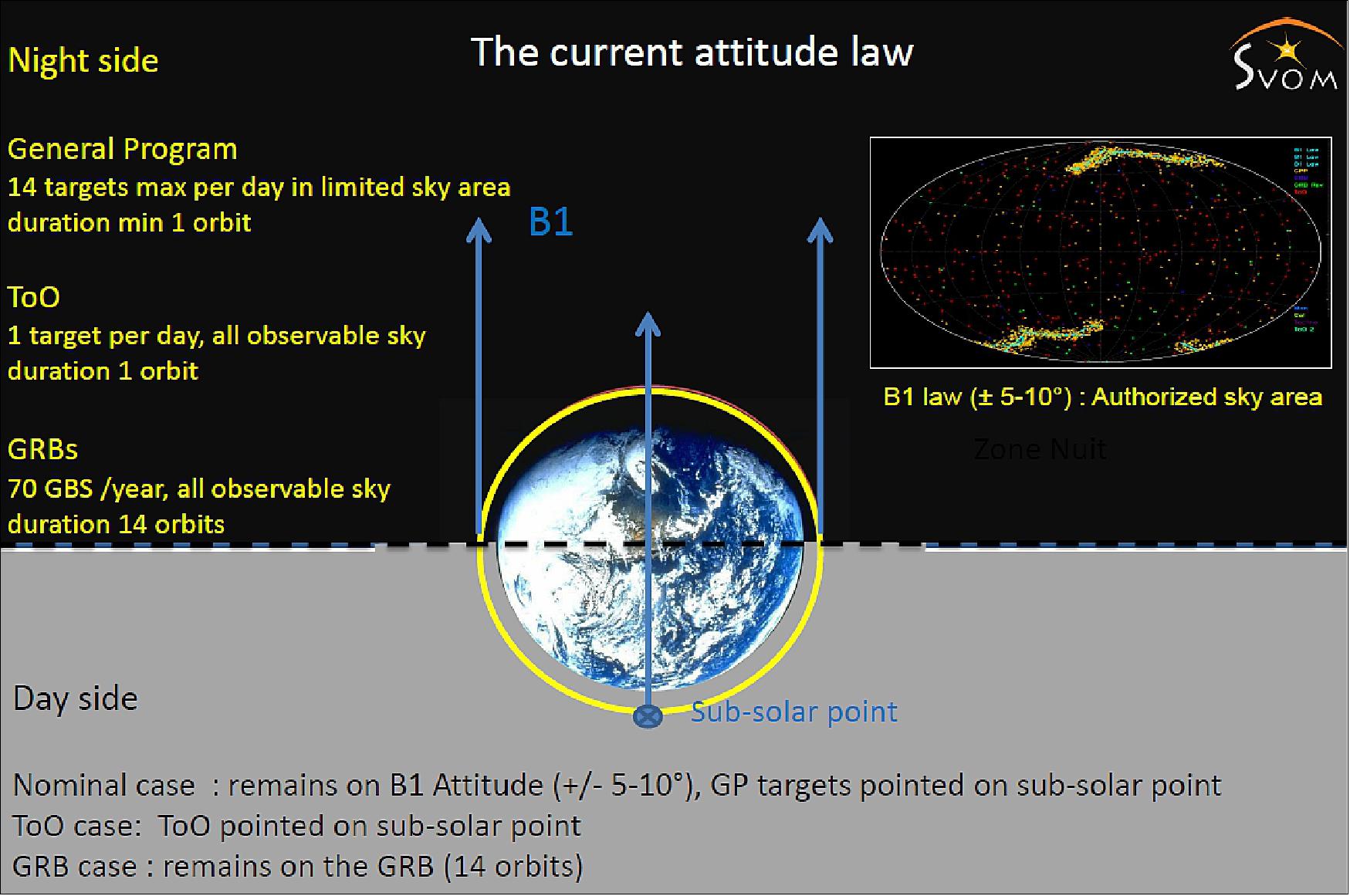
Figure 12: Distribution of the useful time of the mission (image credit: SVOM collaboration)
Distribution of the Useful Time of the Mission
Nominal mission
• Core Program: the GRBs
- 70/year
- duration of observation : 14 orbits (tunable)
• ToO (Targets of Opportunity)
- ToO nominal : 1/day, programming delay 48 hr, duration of observation 1 orbit
- ToO exceptional : 20/year, programming delay <12h, duration of observation 14 orbits (tunable)
• General Program - preplanned observation selected by a TAC (Time Allocation Committee)
- 90% at 5-10° from the B1 law
- 14 targets max per day
- duration of observation 1 orbit minimum
As soon as a GRB will be located, its coordinates and its main characteristics will be sent to the ground within seconds with a VHF antenna. The VHF signal will be received by one of the ~40 ground stations distributed around the Earth below the orbit. The data will then be relayed to the Operation Center, which will send SVOM alerts to the Internet via the GCN and VO Event networks , and to the ground instruments GWAC and the GFTs.
SVOM can also perform target of opportunity observations (with MXT and VT for instance), with a delay of few hours, which depends on the availability of uplink communication with the satellite.
![Figure 15: Telecommand upload link. Sanya is dedicated , the others (Kourou & HBK) are on request. Time delay related to upload the slew commands : 70% [40%] within 6 [4] hours (image credit: SVOM collaboration)](/api/cms/documents/163813/6176201/SVOM_AutoF.jpeg)
SVOM will try to select high-z GRB candidates by analyzing MXT and VT data, and multi-band photometry data from GFTs. If a GRB is detected by MXT in the soft X-rays, but not by VT in the optical band, it will be selected as a candidate of high-z or an optically dark GRB. Ground telescopes with NIR capabilities are encouraged to follow up these candidates as soon as possible to try to measure their redshift. GFTs will be able to measure photometric redshifts by observing GRB afterglows with multiple filters from the visible to the NIR bands.
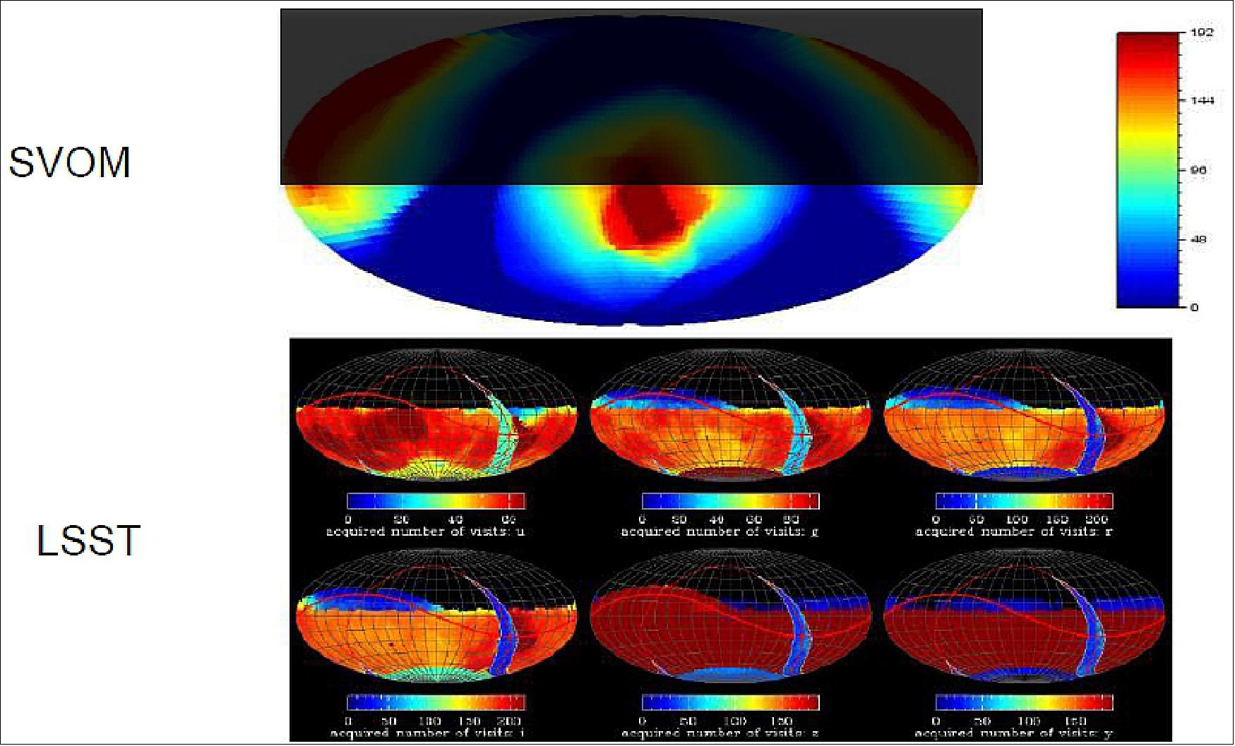
Legend to Figure 17: Each GRB detected in the Southern Sky will be followed by LSST . Thanks to the antisolar choice, the transients sources detected by LSST could be observed immediately by SVOM.
In summary, SVOM will be a highly versatile astronomy satellite, with built-in multi-wavelength capabilities, autonomous re-pointing and dedicated ground followup. With its peculiar pointing strategy and the low energy detection threshold, SVOM is expected to improve the number of GRBs detected at high redshift, and hence to contribute to the use of GRBs as probes of the young Universe. — Beyond the GRB studies emphasized here, SVOM will bring new observations about all types of high energy transients, in particular those of extragalactic origin (TDEs, AGNs, etc.).
Sensor Complement
The main SVOM general objective is the survey of GRBs (Gamma Ray Bursts), in coordination with ground telescopes. The other main on-board instruments are ECLAIR (Gamma-ray Imager), GRM (Gamma Ray Monitor) and VT (Visible Telescope). The MXT (Microchannel X-ray Telescope) is based on a cooled silicon-based detector, provided by the Max-Planck-Institut für Extraterrestrische Physik (MPE) and encapsulated in a camera developed by CEA, and a set of microchannel plates manufactured by Photonis Technologies SAS (France).
SVOM is composed of four instruments: ECLAIRs, for detecting X-ray and gamma-ray transients (4-250 keV); GRM, a gamma-ray spectrometer (15 keV-5 MeV); VT, a visible telescope and the Microchannel X-ray Telescope (MXT). The MXT’s main goal is to precisely localize, and spectrally characterize X-ray afterglows of Gamma-Ray Bursts. The MXT is a narrow-field-optimized lobster eye X-ray focusing telescope comprising an array of 25 square Micro Pore Optics (MPOs), with a detector-limited field of view of ~1º 2, working in the energy band 0.2-10 keV. The SVOM qualification model (QM) MXT optic (MOP) was designed and built at the University of Leicester, and is the first complete, lobster eye optic to be X-ray tested. We present results from the PANTER facility (MPE), where a full calibration of the QM MOP was carried out. The response of the optic was studied at seven energies from C-K to Cu-K, and the effective area at multiple off-axis angles at each energy was measured. The focal length of the MOP was confirmed and the PSF (Point Spread Function) was studied on and off-axis. In addition, we present details of the modelling and analysis, which was used to calculate the results from the test campaign. The effective area and PSF are in good agreement with the modelling, indicating that the optic is performing as expected. 20)
ECLAIRs (Gamma-ray Imager)
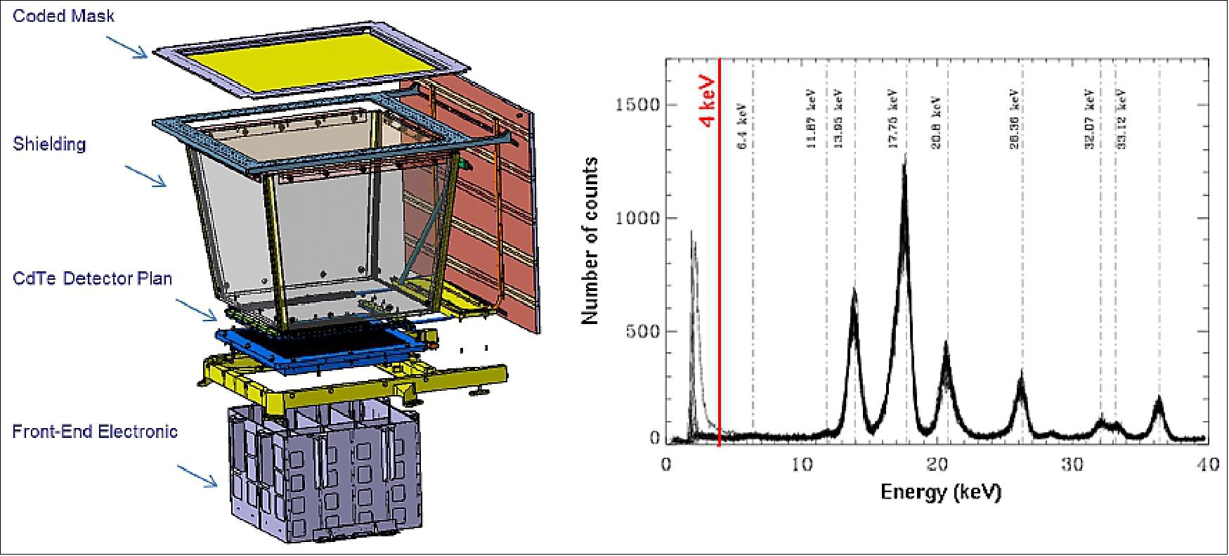
The ECLAIRs project of CNES is managed by CEA Saclay (Commissariat à l'Energie Atomique), France. ECLAIRs (Figure 19) is the instrument on board the satellite that will detect and locate the GRBs. ECLAIRs is made of four parts: a pixelated detection plane (1024 cm2) with its readout electronics, a coded mask, a shield defining a field of view of 2 steradians (89º x 89º), and a processing unit in charge of detecting and locating transient sources. The detection plane is made of 200 modules of 32 CdTe detectors each, for a total of 6400 detectors of size 4 x4 x 1 mm. Each module is read by a customized ASIC connected to an electronics that encodes the position, the time and the energy of each photon. One of the requirements of ECLAIRs is to reach an energy threshold of 4 keV, in order to study soft GRBs (Gamma Ray Bursts) like X-Ray flashes and highly redshifted GRBs. 21) 22)
As shown in Figure 19, the first modules satisfy the low energy threshold requirement. 23) The coded mask is a square of side 54 cm located at a distance of 46 cm from the detection plane; it has an opening fraction of 40% and provides a localization accuracy of several arc minutes (~14' for a source at the limit of detection). The instrument features a count rate trigger and an image trigger, like Swift. These triggers are computed, from the photon data, in several energy bands and on time-scales ranging from 10 ms to several minutes. Our simulations show that ECLAIRs will detect 70-80 GRBs/year.
CNES is the prime contractor for the ECLAIRs and MXT instruments. The ECLAIRs telescope is developed by CEA-IRFU in partnership with the French laboratories IRAP at Toulouse and APC in Paris. The MXT instrument is developed by the laboratories CEA-IRFU at Saclay, LAM Marseille, MPE Garching and the University of Leicester. The Astrophysical Department of CEA-IRFU is also responsible for the development of the antenna array and the scientific expertise center. 24)
GRM (Gamma Ray Monitor)
GRM is a gamma-ray non-imaging spectrometer will extend the prompt emission energy coverage. GRB (Gamma Ray Burst) alerts are sent in real-time to the ground observers community.
GRM consists of a set of three detection modules. Each of them is made of a scintillating crystal (sodium iodide), a photomultiplier and its readout electronics. Each detector has a surface area of 200 cm2 and a thickness of 1.5 cm. One piece of plastic scintillator in front of NaI(Tl) is used to distinguish low energy electrons from normal X-rays. The three modules are pointed at different directions to form a total field of view of 2 sr, within which rough (of the order of 10 degrees radius) localization of transient sources can be achieved on-board.
The energy range of the GRM is 15-5000 keV, extending the energy range of ECLAIRs towards high energies to measure EPeak for a large fraction of SVOM GRBs. The project expects that GRM will detect > 90 GRBs/yr. GRM will have a good sensitivity to short/hard GRBs, like the GBM of Fermi. GRM can generate on-board GRM-only triggers, taking use of only GRM detectors. Such triggers with localization information will be transferred to ECLAIRs for trigger enhancement on the short GRBs, and to ground facilities (e.g. GWAC, GW experiments) for joint observations. A calibration detector containing one radioactive 241Am isotope is installed on the edge of each detection module, for the purpose of gain monitoring and energy calibration. In addition, a particle monitor auxiliary to GRM can generate South Atlantic Anomaly alerts and help protecting the detection modules.
MXT (Microchannel X-Ray Telescope)
MXT is soft X-ray instrument on board SVOM, featuring a cooled silicon detector, provided by MPE (Max-Planck-Institut für Extraterrestrische Physik). MXT is a very light (<35 kg), and compact (<1.2 m) focusing X-ray telescope. Its large field of view (1 degree) and its sensitivity below the mCrab level make of MXT a very good instrument to identify and precisely localize (below the arc minute) X-ray transients in non-crowded fields, and to study them in detail, thanks to its excellent spectral response. It is designed to measure radiation from 0.2 to 10 Kev with a maximum sensitivity around 1 keV. MXT is designed to measure radiation from 0.2 to 10 keV. 25)
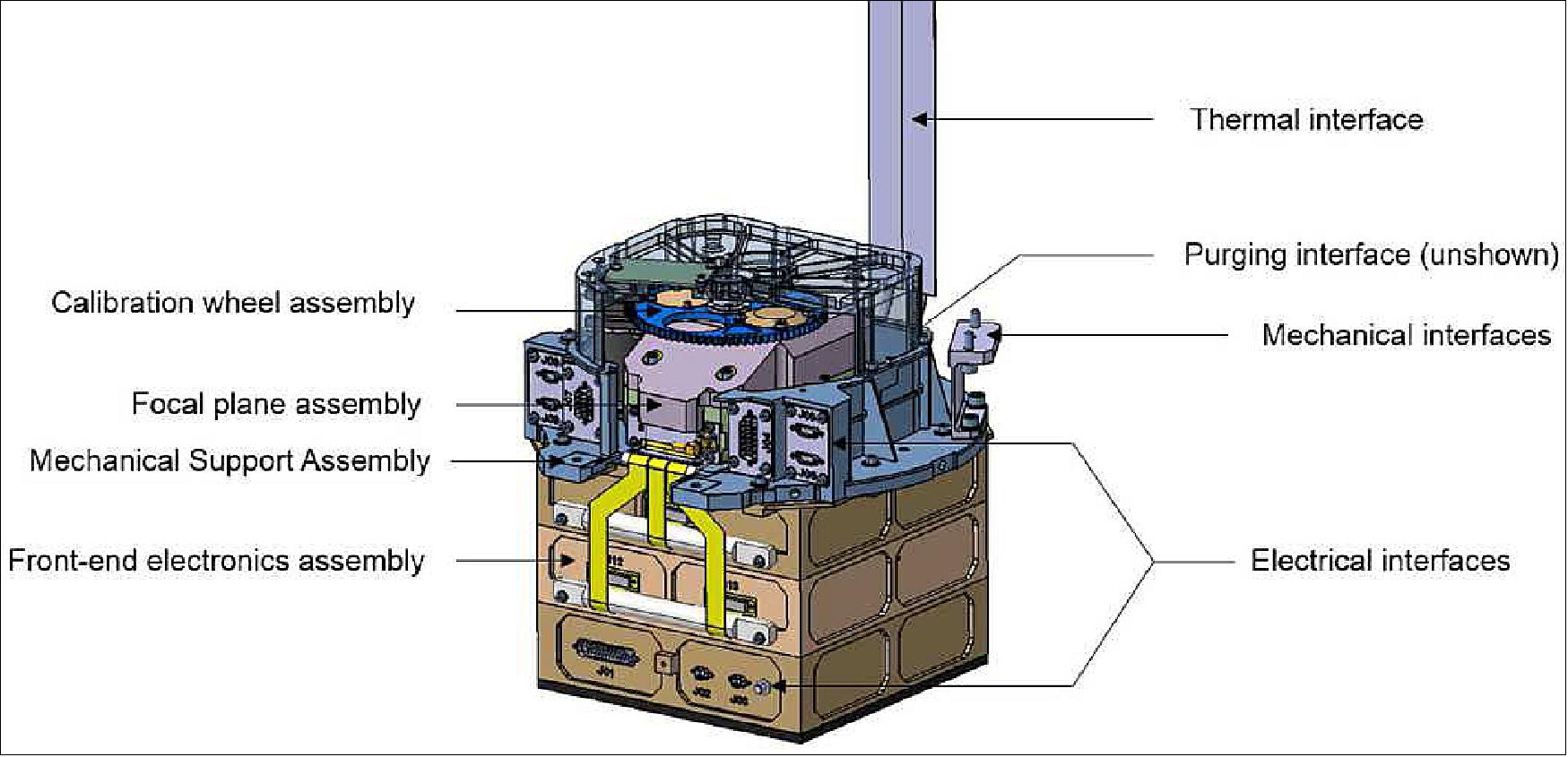
MXT is composed by five main subsystems: an optical module based on square MPO (Micro-Pore Optics), a camera, a carbon fiber structure, a data processing unit and a radiator (Figure 20). A small baffle provides a protection against direct sun illumination. The interface with the satellite is made through 3 fixation zones and a titanium ring. The nominal focal length of the instrument is F=1 m, although studies are going on to increase it to 1.15 m.
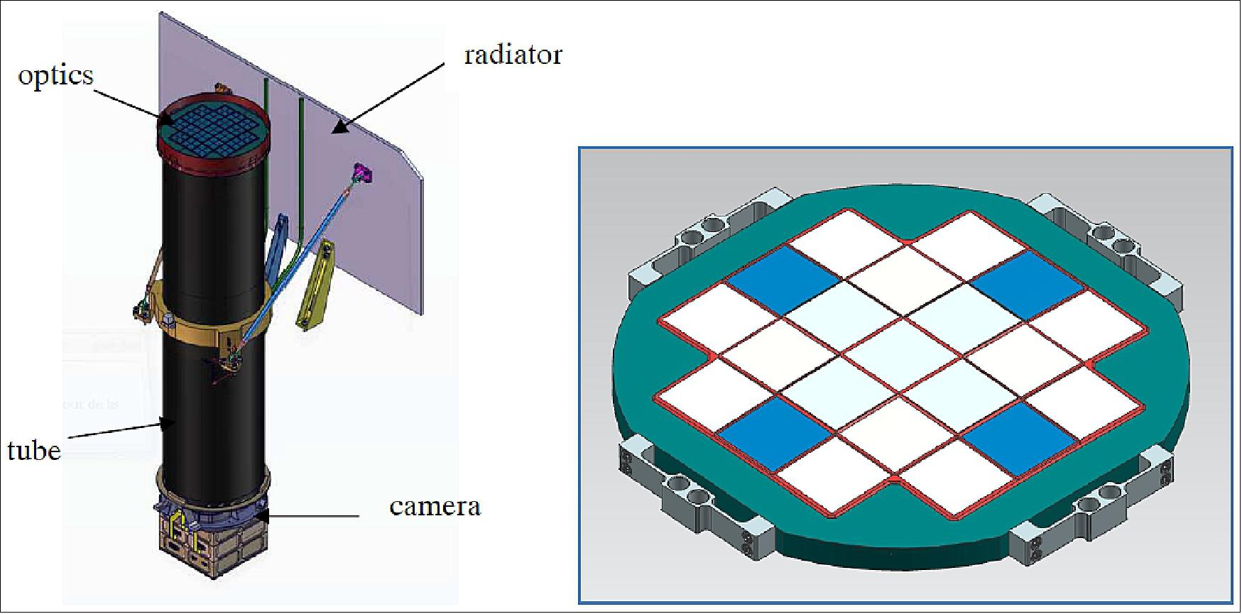
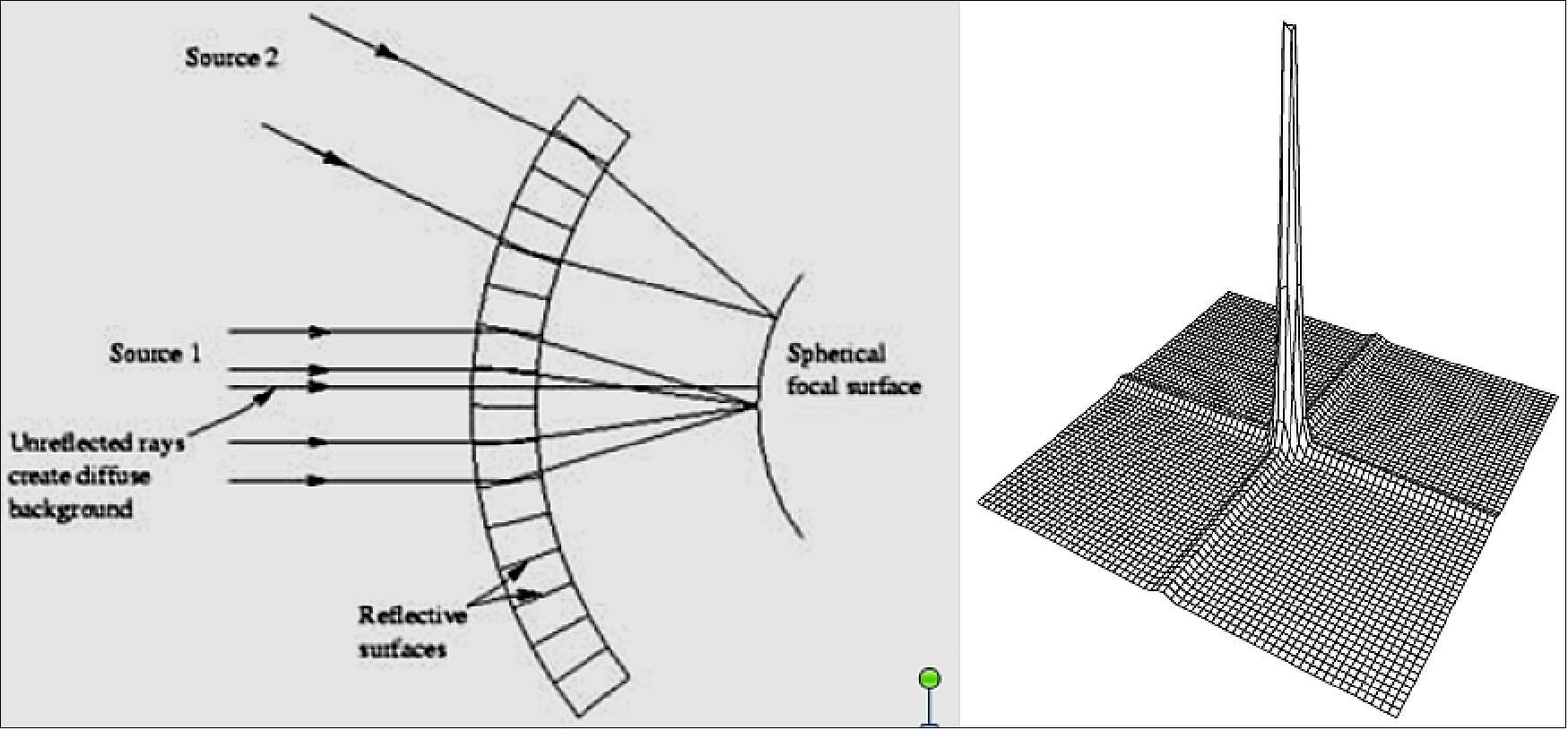
The optics of MXT is based on a “Lobster Eye” geometry and optimized for a narrow-field use (Figure 21 left). The rays hit the inner walls of the micro-pores with grazing incidence. The pores are square with d=40 µm size and a pitch of p=52 µm. The inner walls are coated with a 25 nm Ir layer to boost the reflectivity. The pores are grouped in plates of 40 x 40 mm side (600,625 pores), 21 of them are used to full the aperture (Figure 20, right). Their thickness is optimized to avoid vignetting and maximize the effective area. The central plates have L=2.4 mm thickness while the outermost ones have L=1.05 mm. They are bonded on an aluminum frame which upper face is a sphere of radius 2000 mm, with 10 µm machining precision. The MPO are covered with a 70 nm Aluminum film to avoid thermal flux and straylight from entering the instrument.
The PSF (Point Spread Function) has a peculiar form, and is composed by a central spot and two cross arms (Figure 21, right): X-rays entering in the MPOs can either be reflected twice and focused in the central PSF spot, or reflected just once and focused in the PSF arms. For MXT, about 50% of the incident X-ray flux is focused in the central spot, 2 x 22% in the arms, and the rest in a diffuse patch. Thanks to the “Lobster Eye” geometry the vignetting is very low, of the order of 10-15% at the edge of the FOV.
Camera: The PSF is imaged on a silicon (Si) based pn CCD having 256 x 256 75 µm side pixels associated with FEE (Front-End Electronics) based on two CAMEX. It is fully depleted (450 µm depth) and has excellent low-energy response (45-48 eV (FWHM) @ 277 eV), and energy resolution (123-131 eV FWHM @ 5.9 keV). The spatial sampling is good enough to avoid any degradation of the PSF. The CCD is thermally controlled by 3 TEC (Thermoelectric Cooler) at -65°C (to reduce noise) with a daily stability better than ±1ºC. The CCD is covered by a 100 nm Aluminum layer to protect against UV/Visible straylight because the CCD is still sensitive in this spectral range. This results in a slight transmission loss in the X-ray range. It is also protected against background X-rays by an aluminum shielding. A filter wheel can put various filters in front of the CCD and its entrance cone. The external box of the camera provides the interfaces with the radiator, the front end electronics and the tube (Figure 22).
With a 1.0 m focal length, each pixel corresponds to 15.4 arcsec. The FOV is in practice limited by the CCD and is a 57 x 57 arcmin square. At 20 arcmin FOV radius the vignetting factor is greater than 0.9.
The instrument effective area is a combination of the optics effective area, the transmission of the aluminum filters, the size of the CCD and its quantum efficiency.
X-rays: The PSF at the center of the FOV was extensively studied by UoL with a dedicated software. We report here a comparison of what we obtained with Zemax in a simplified manner.
Modeling in Zemax: Zemax is a general optical software widely used in the world and which benefits from a high level of validation. It can be used to model small wavelengths provided the objects are not too small (>10 λ) and the index data are available. For this last point, we used the database of CXRO (Center for X-Rays Optics). The size of the pores and of the wedges between them (few μm to tens of μm) is much larger than the criteria of 10 λ (here typically 10 nm).
The glass used for the MPO has a high density. Hence, in the soft X-rays range, even a small thickness of glass is enough to stop rays. This allows to consider only reflected rays and to use traditional ray tracing in a quite simple manner.
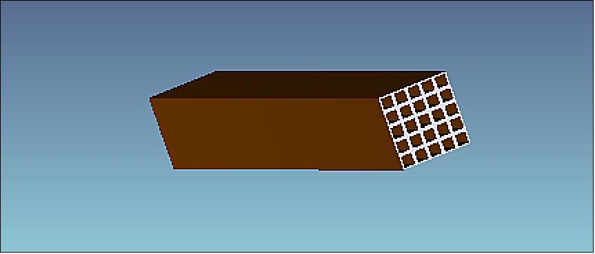
In NSC (Non-Sequential Sources) mode, Zemax assumes that all the objects are defined before launching the rays. The basic element we use is an “extruded object”. By defining a section and stretching it along one direction, Zemax can represent this way pores or group of pores. As it is impossible to represent simultaneously the ~12 million pores involved in MXT optics, the way to proceed is to represent a small subset of pores, launch rays for this subset, measure the energy on a detector, move the subset onto the aperture and cumulate the energy deposited on the CCD. The programming of this loop can be done using the ZPL language and dedicated macros. The spherical geometry of the “lobster eye” is quite easy to implement. Various manufacturing errors can be introduced at the subset level, like an orientation error or a pore shape error. Performing this process with a subset of 1 pore is much too fine and takes a too long time to simulate. We found that using a 5 x 5 pores subset (Figure 23), with uniform manufacturing errors at this scale, was a good compromise between computation time and representativeness of the geometry. 25 of this objects forms a multi-fiber (25 x 25 pores).
The number of rays to launch plays an important role. To avoid excessive time computation ones has to use the minimum number of rays to correctly represent the PSF. We performed some tests with increasing number of rays and we found that having 10 to 100 rays for one multi-fiber (625 pores) was sufficient to have better than 1% precision results. The source object is just a rectangle, the size of a multi-fiber.
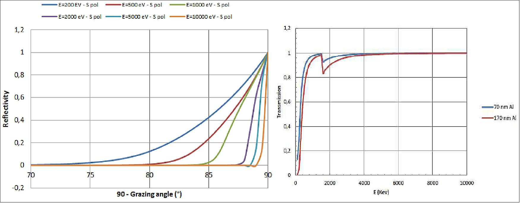
The reflectivity of the 25 nm Ir layer is modelled with tabulated data from the CXRO database (angle, wavelength) assuming a roughness of 1.3 nm rms (Figure 24, left). The 70 nm aluminum film in front of the MPO plays a role in the effective area, so its transmission as to be taken into account (Figure 24, right, CXRO database). - The detector is modelled simply as an array of 256 x 256 75 µm size pixels.
Perfect geometry and pores: Assuming perfect pores and a perfect geometry, the FWHM of the PSF central spot is limited by three aberrations:
• Spherical aberration: Δθs= 4 √2 (d/L)3
• Diffraction: Δθd= 2 (λ/d)
• Geometric pore size: Δθg= d/F
For the adopted MXT parameters, the three aberrations have approximately the same value, 10 arcsec.
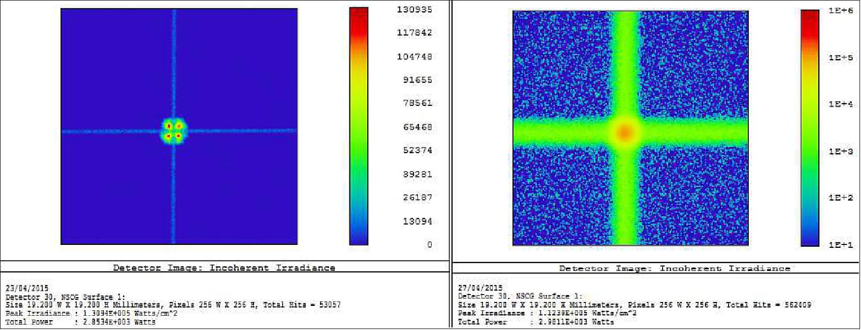
MPO manufacture errors: In the end, the FWHM is not dominated by these factors but by the manufacturing errors which lead to imperfect geometry and limit the FWHM. The two most important ones are the pore shear and the pore alignment errors. The first one is a distortion of the pore shape from a square to a parallelogram (angle θh). It is introduced when the square flat MPO is slumped onto a spherical tool under pressure. It is more important in the corners of a MPO plate than in the center. The pore alignment error (angle θa) is induced by the stacking process or the slumping. The axis of the pores is no more aligned with the normal to the spherical surface, deviating the output rays with an angle twice that of the alignment error. Another important error is the pore figure error (angle θf): the inner walls of the pores are not perfectly flat but have low order WFE (Wavefront Errors) which depend mainly on the etching process. The effect of qa and qf overlaps and are not easily separated. Typical values from UoL are θh =0.3° and θaf =0.75 arcmin.
In our simulations we assumed that qh is constant over one MPO and θaf can be represented by a gaussian error with 0.75 arcmin rms standard deviation. No finer dependence of these errors with the position in one plate (corner / edge / center) has been taken into account. The typical effect of the shear error is found (Figure 25, left): the main peak is split into four smaller peaks. Cumulating all the errors (Figure 25, right), we found a 4.1 arcmin FWHM to be compared with the 4.4 arcmin of UoL. These results are in good agreement given the simplifications we made.
The effective area could also be computed at various energies and is compared with the UoL data on Figure 26 (left). The Zemax results fit reasonably well with UoL data within a 10-15% precision.
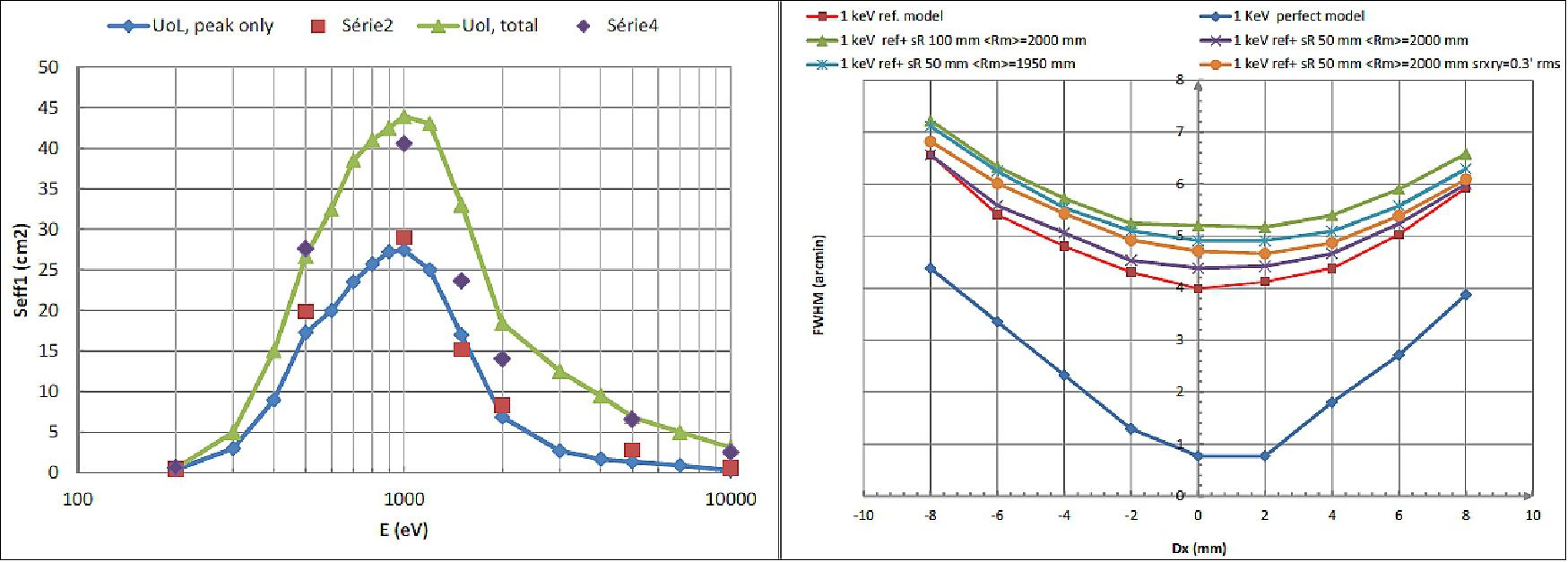
EUV (Extreme Ultraviolet): The aluminum film on the MPO has a transmission window in the EUV spectral range (Figure 27). For the GRB localization, this could be a problem if bright sources are in the vicinity because of the induced noise. That’s why we studied the optical response in this range. The previous computations performed in X-rays can be extended in the EUV range, but the diffraction has now to be taken into account as the diffraction angle is Δθd =3.4 to 8.6 arcmin when l varies from 40 to 100 nm. One way to put diffraction in Zemax NSC mode is to use a diffractive source instead of a normal one. Unfortunately this only works for simple source shapes, like a square. The previously described computation procedure can be adapted, but using a single pore as a basic object and taking advantage of MPO symmetries. This lead to quite high computation time on a standard PC (few days) but remains feasible if not too much runs are required. The scattering is not taken into account directly, but the reflection coefficients computed in the CXRO database are taken with 1.3 nm rms roughness (at 40 nm, supposed to be constant up to 80 nm).
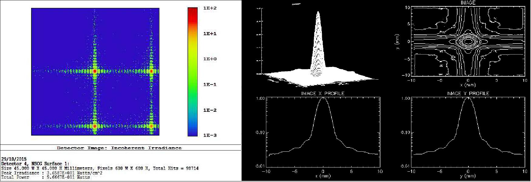
Figure 27 shows the diffraction of one pore (left) and the simulated PSF for the full aperture at 80 nm including manufacturing errors (right). We found that the FWHM is 5.1 arcmin at 40 nm and 7 arcmin at 80 nm. It is very close to a quadratic sum of the FWHM without diffraction and the Δθd value. The effective area of the central spot without the Al transmission is close to 43 cm2 (including 170 nm Al transmission, we have 28 and 6 cm2 at 40 and 80 nm).
So MXT forms focused images of EUV sources, with a significant effective area and with a FWHM enlarged by the diffraction. At higher wavelength (> 200 nm), the diffraction dominates and becomes huge so that no focused image is formed. Estimations show that a G2V star at 100 pc (EUV flux leads to 0.6 x 10⁻⁵ e-/px/0.1s. For a O9V star at 300 pc, we get 3800 e-/px/0.1s. In some cases, bright EUV sources in the FOV could be a problem for MXT if it is used to point in too crowded areas. A dedicated filter will be placed on the filter wheel.
Results: The Earth is the main optical straylight source for MXT. The important parameter to study is the guard angle between the instrument boresight and the earth limb, as this is an operational constraint for the mission. The current proposed value is 20°, derived from the SWIFT mission. As the satellite altitude is about 600 km, MXT has potentially a large portion of the Earth in its field of view. Using the PST previously computed, the orbital parameters, the Earth flux from SPOT satellites data and for UV Earth albedo, a 2D integral over the portion of Earth having a factor of view with the optic entrance pupil can be computed numerically. It is multiplied by the transmission of the 70 nm film (t70), including the 1/cosi effect on the thickness, the transmission of the 100 nm coating on the CCD (t100) and the efficiency ήq of the CCD . t70 includes a fraction u of “open” pores per MPO with unity transmission. They result from defaults in the aluminum film and depressurization during the launch. The current requirement is u=50.
With the baseline design (dark blue curve, diamond), the noise limit is reached at 12° angle. For this value, the integral is dominated by a small area of the earth with the minimal incidence angles on the optics (i ranging from 10 to 25°). At 20° angle the margin is quite good (factor of 5). For low guard angles, the dominating paths to the CCD are the specular rays out of the pores hitting indirectly the CCD after reflection on the tube walls. When increasing the guard angle, the portion of the Earth seen by the optics decreases. The incident power on the optics decreases from 8.3 to 2.3 W when varying from 10 to 40°. Also, the average incidence angle increases, hence the collecting area decreases with cosi. The integral is less dominated by a small area. The scattered rays in the pores with direct path to the CCD dominate more. Spectrally, the noise is dominated by near IR because of the increasing transmission of the Al film in this range, despite the low energy of the photons.
In summary, by using Zemax, we could model the in FOV X-rays properties of MXT optics. The obtained results are well in line with the UoL predictions using the state of the art for manufacturing errors: 0.75 arcmin for pore alignment/figure error and 0.3° for the shear error. We find that during assembly of the MPO on the frame, tip/tilt errors shall be lower than 1 arcmin. Furthermore, the standard deviation of the MPO radius of curvature shall be less than 50 mm rms. The optics also forms an image in the EUV range but it is enlarged due to diffraction. As the collecting area is not negligible, care as to be taken with bright sources in the FOV while detecting a GRB. A dedicated filter is implemented on the wheel. The straylight analysis shows that the sun is not a problem because the radiator and the other instruments are lower than the aperture. The moon has a negligible effect and could be as close as 10° from the instrument boresight. The earth will be the dominating straylight source in the visible/IR. The 20° guard angle is safe with a quite good margin. Given the many uncertainties of our computations it is not possible to lower this limit. The tube inner walls shall be covered with a diffusive black paint. No long baffle is required, only a short one to prevent the sun from hitting directly the optics in some rare cases. Further work will include a more precise model of the various errors, especially the recently measured distortions occurring at the multi-fiber interfaces, and test on samples to validate the models.
VT (Visible Telescope)
VT is a dedicated optical follow-up telescope on board the SVOM satellite. Its main purpose is to detect and observe the optical afterglows of gamma-ray bursts localized by ECLAIRs. It is a Ritchey-Chretien telescope (Figure 28) with a diameter of 40 cm and an f-ratio of 9. Its limiting magnitude is about 22.5 (MV) for an integration time of 300 seconds VT is designed to maximize the detection effciency of GRB's optical afterglows.
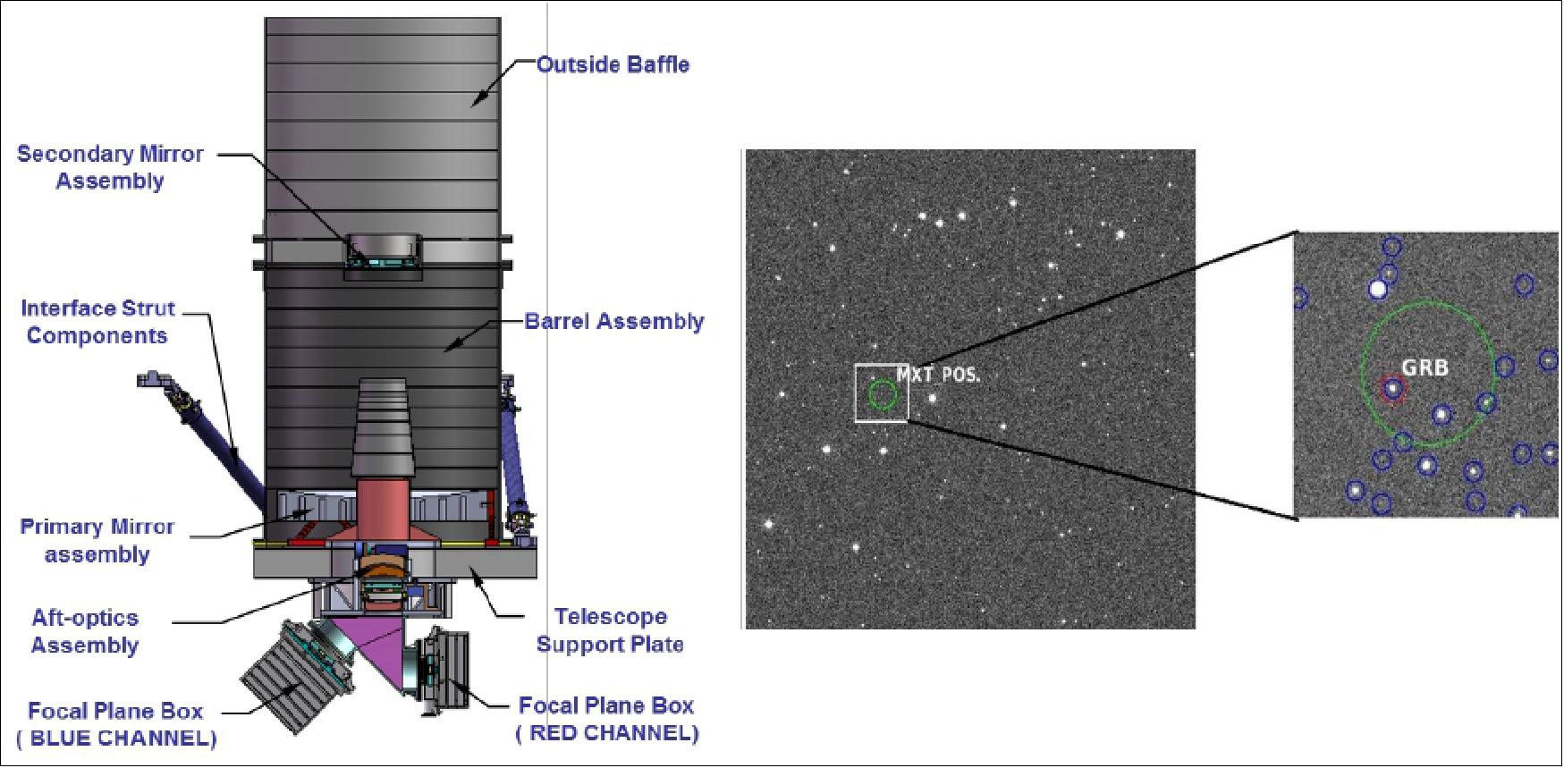
Instead of a filter wheel, a dichroic beam splitter is used to divide the light into two channels, in which the GRB afterglow can be observed simultaneously. Their wavelength ranges are from 0.4 µm to 0.65 µm (blue channel) and from 0.65 µm to 1 µm (red channel). Each channel is equipped with a 2k x 2k CCD detector. While the CCD for the blue channel is a normal thinned back-illuminated one, a deep-depleted one is adopted for the red channel to obtain high sensitivity at long wavelengths. The QE (Quantum Effciency) of the red-channel CCD at 0.9 µm is over 50%, which enables VT to have the capability of detecting GRBs with the redshift larger than 6.5. The field of view of VT is about 26 ' x 26', which can cover the error box of ECLAIRs in most cases. Both CCDs have a pixel size of 13.5 µm x 13.5 µm, corresponding to spatial resolutions of 0.77 arcsec. This ensures the GRB positioning accuracy to be greatly improved by VT from several arcmin (ECLAIRs) and tens of arcsec (MXT) to a level of sub-arcsec.
In order to promptly provide the GRB alerts with the sub-arcsec accuracy, VT will do some data processing on board. After a GRB has been localized by the coaligned MXT, lists of sources are extracted from the VT sub-images whose centers and sizes are determined by the GRB positions and the corresponding error boxes provided by MXT. The lists are immediately downlinked to the ground through the VHF network. Then, the ground software will make finding charts with these lists (Figure 28) and search the optical counterparts of the GRB by comparing the lists with the existing catalogs.
If a counterpart is identified, an alert will be then produced and distributed to the world-wide astronomical community, which is useful for triggering large ground-based telescopes to measure the redshifts of the GRBs by spectroscopy. VT is expected to do a good job on detecting high-redshift GRBs. The confirmed high-redshift GRBs are rare in the Swift era, in contrast to a theoretical prediction of a fraction of more than 10%. 26)
This is probably due to the fact that for most Swift GRBs the early-time optical imaging follow-up is not deep enough for a quick identification and some faint GRBs cannot be spectroscopically observed in time by the large ground-based telescopes. This passive situation will be significantly improved by SVOM, due to the high sensitivity of VT, in particular at long wavelength, and the prompt optical-counterpart alerts. Additionally, the anti-solar pointing strategy of SVOM allows GRBs to be spectroscopically observed by large ground-based telescopes at the early time of the bursts. Consequently, more high-redshift GRBs are expected to be identified in the SVOM era. VT is also used to support the platform to achieve the required high pointing stability. A FGS (Fine Guidance Sensor) is mounted on the VT focal plane to measure relative image motions. Its images are processed in real-time by a specialized data processing unit to get the centroid positions of several stars brighter than the magnitude of 15 (MV ). The results are sent at a frequency of 1 Hz to the platform to improve the pointing stability, which enables VT to have a good performance in a long exposure time.
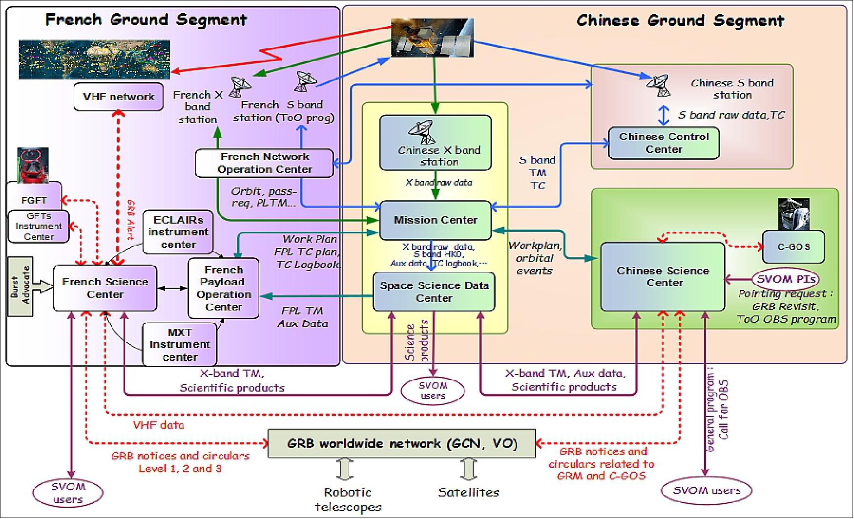
Ground Segment
The SVOM Ground Segment consists of Chinese Command Control Ground Segment (CCGS) and Mission Science Ground Segment (MSGS) including a Chinese part (C-MSGS) and a French one (F-MSGS).
Ground Based Instruments
The ground follow-up instruments constitute an important part of the mission. Three instruments are developed for the follow-up of SVOM GRBs: a wide angle camera that surveys a significant fraction of the sky for transients, and two robotic telescopes. In addition to these dedicated instruments, the SVOM collaboration will seek agreements with various existing telescopes or networks willing to contribute to the follow-up of SVOM GRBs.
GWAC (Ground Wide Angle Camera)
GWAC (Figure 30) provides a unique way to survey a large field of view for optical transients. The instrument will monitor 63% of ECLAIRs field of view, looking for optical transients occurring before, during and after GRBs. GWAC will also have its own trigger system, providing alerts to the world. GWAC is a complex system: the heart of the system is a set of 36 wide angle cameras with a diameter of 18 cm and a focal length of 22 cm, together these cameras cover a field of view of 60 º x 60º. They use 4k x 4k CCD detectors, sensitive in the range of wavelength 500-800 nm. These cameras reach a limiting magnitude V=16 (5σ) in a typical 10 second exposure. This set of cameras is completed by two 60 cm robotic telescopes. equipped with EMCCD cameras. These telescopes will provide multicolour photometry of the transients discovered by GWAC with a temporal resolution ≤ 1 second.
GFTs (Ground Follow-Up Telescopes)
The ground follow-up telescopes have two main goals. Firstly, they measure the photometric evolution of the optical afterglow in the first minutes after the trigger in a broad range of visible and NIR wavelengths, with a temporal resolution of few seconds. Secondly, when an afterglow is detected, they provide its position with arc second precision within 5 minutes of the trigger. Some essential features of the GFTs are their field of view, their size, and their sensitivity in the near infrared. The field of view (~30 arc minutes) enables observing quickly the entire error boxes of ECLAIRs. The size, typically 1 meter, allows the detection of all visible (i.e. non-dark) afterglows at the condition to arrive within few minutes after the trigger. 27) 28)
Finally, the near infrared sensitivity permits the detection of high-z GRBs and GRBs extinct by dust, whose afterglow are obscured in the visible domain. 29) GFTs are especially useful for the study of the early afterglow during the slew of the satellite, and for the rapid identification of the optical afterglow in various cases: when SVOM cannot slew to the burst or when the slew is delayed due to pointing constraints, and when the optical afterglow is only visible in the NIR. One telescope is located in China at Xinglong Observatory and the other one will be located in Mexico at San Pedro Martir.
References
1) Francois Gonzalez, Shunjing Yu, ”SVOM: A French/Chinese cooperation for a GRB mission,” Proceedings of the 70th IAC (International Astronautical Congress), Washington DC, USA, 21-25 October 2019, paper: IAC-19-A7.1.3, URL: https://iafastro.directory/iac/proceedings/
IAC-19/IAC-19/A7/1/manuscripts/IAC-19,A7,1,3,x49297.pdf
2) B. Cordier, J. Wei, J.-L. Atteia, S. Basa, A. Claret, F. Daigne, J. Deng, Y. Dong, O. Godet, A. Goldwurm, D. Götz, X. Han, A. Klotz, C. Lachaud, J. Osborne, Y. Qiu, S. Schanne, B. Wu, J. Wang, C Wu, L. Xin, B. Zhang, S.-N. Zhang, ”The SVOM gamma-ray burst mission,” Proceedings of Science, Dec. 10, 2015, URL: https://arxiv.org/ftp/arxiv/papers/1512/1512.03323.pdf
3) D. Götz, J. Paul, S. Basa, J. Wei, S. N. Zhang, J.-L. Atteia, D. Barret, B. Cordier, A. Claret, J. Deng, X. Fan, J.Y. Hu, M. Huang, P. Mandrou, S. Mereghetti, Y. Qiu, B. Wu, ”SVOM: a new mission for Gamma-Ray Burst Studies,” AIP Conference Proceedings, June 23, 2009, URL: http://arxiv.org/pdf/0906.4195v1.pdf
4) http://www.svom.fr/en/#filter=.accueil
5) Bertrand Cordier, Jianyan Wei, ”The SVOM mission,” URL: https://ocevuaprom.sciencesconf.org/data/program/OCEVU_SVOM_Cordier.pdf
6) J. Wei, B. Cordier, S. Antier, P. Antilogus, J.-L. Atteia, A. Bajat, S. Basa, V. Beckmann, M.G. Bernardini, S. Boissier, L. Bouchet, V. Burwitz, A. Claret, Z.-G. Dai, F. Daigne, J. Deng, D. Dornic, H. Feng, T. Foglizzo, H. Gao, N. Gehrels, O. Godet, A. Goldwurm, F. Gonzalez, L. Gosset, D. Götz, C. Gouiffes, F. Grise, A. Gros, J. Guilet, X. Han, M. Huang, Y.-F. Huang, M. Jouret, A. Klotz, O. La Marle, C. Lachaud, E. Le Floch, W. Lee, N. Leroy, L.-X. Li, S. C. Li, Z. Li, E.-W. Liang, H. Lyu, K. Mercier, G. Migliori, R. Mochkovitch, P. O'Brien, J. Osborne, J. Paul, E. Perinati, P. Petitjean, F. Piron, Y. Qiu, A. Rau, J. Rodriguez, S. Schanne, N. Tanvir, E. Vangioni, S. Vergani, F.-Y. Wang, J. Wang, X.-G. Wang, X.-Y. Wang, A. Watson, N. Webb, J. J. Wei, R. Willingale, C. Wu, X.-F. Wu, L.-P. Xin, D. Xu, S. Yu, W.-F. Yu, Y.-W. Yu, B. Zhang, S.-N. Zhang, Y. Zhang, X.L. Zhou, ”The Deep and Transient Universe: New Challenges and Opportunities - Scientific prospects of the SVOM mission,” Proceedings of the SVOM sientific workshop, Les Houches School of Physics, France, 10-15 April 2016, Published on 21 October 2016 (astro-ph.IM), URL: https://arxiv.org/pdf/1610.06892.pdf
7) B. Cordier, D. Götz, and C. Motch, on behalf of the SVOM collaboration, ”The SVOM mission, a pathfinder for THESEUS,” Mem. S.A.It (Memorie della Societa Astronomica Italiana), Vol. , 1 c SAIt 2008, 5 Feb., 2018, URL: https://arxiv.org/pdf/1802.01681.pdf
8) S. Schanne, J. Paul, J. Wei, S.-N. Zhang, S. Basa, J.-L. Atteia, D. Barret, A. Claret, B. Cordier, F. Daigne, P. Evans, G. Fraser, O. Godet, D. Götz, P. Mandrou, J. Osborne, ”The future Gamma-Ray Burst Mission SVOM,” Proceedings of Science, May 2010, URL: https://arxiv.org/pdf/1005.5008.pdf
9) Paul A. Abell, Julius Allison, Scott F. Anderson, John R. Andrew, J. Roger P. Angel, Lee Armus, David Arnett, S. J. Asztalos, Tim S. Axelrod, Stephen Bailey, D. R. Ballantyne, Justin R. Bankert, Wayne A. Barkhouse, Jeffrey D. Barr, L. Felipe Barrientos, Aaron J. Barth, James G. Bartlett, Andrew C. Becker, Jacek Becla, Timothy C. Beers, Joseph P. Bernstein, Rahul Biswas, Michael R. Blanton, Joshua S. Bloom, John J. Bochanski, Pat Boeshaar, Kirk D. Borne, Marusa Bradac, W. N. Brandt, Carrie R. Bridge, Michael E. Brown, Robert J. Brunner, James S. Bullock, Adam J. Burgasser, James H. Burge, David L. Burke, Phillip A. Cargile, Srinivasan Chandrasekharan, George Chartas, Steven R. Chesley, You-Hua Chu, David Cinabro, Mark W. Claire, Charles F. Claver, Douglas Clowe, et al., ”LSST Science Book, Version 2.0,” Dec. 1, 2009, URL: https://arxiv.org/pdf/0912.0201.pdf
11) Huadong Guo, Ji Wu, ”Space Science & Technology in China: A Roadmap to 2050,” Springer-Verlag, 2010, URL: http://www.springer.com/la/book/9783642053412
12) M. Bode, ”ASTRONET, a comprehensive long-term planning for development of European astronomy,” 2015, URL: http://www.astronet-eu.org
13) ”Astro2010: The Astronomy and Astrophysics Decadal Survey,” 2010, URL: http://sites.nationalacademies.org/bpa/bpa_049810 and URL: https://science.nasa.gov/astrophysics/
special-events/astro2010-astronomy-and-astrophysics-decadal-survey
14) K. Lacombe, J. P. Dezalay, B. Houret, C. Amoros, J-L.Atteia, L. Bouchet, B. Cordier, O. Gevin, O. Godet, F. Gonzalez, Ph. Guillemot, O. Limousin, R. Pons, P. Ramon, V. Waegebaert, ”Spectral performance of ECLAIRs flight detectors on SVOM mission,” Astroparticle Physics, Volume 103, December 2018, Pages 131-141, Published online 8 August 2018, https://doi.org/10.1016/j.astropartphys.2018.08.002
15) Marie-Claire Charmeau, Valerie Mousset, Martine Jouret, Yonghe Zhang, Xingbo Han and Binpin Su, ”SVOM payload mission operation concept,” Proceedings of the SpaceOps Conference, 28 May - 1 June 2018, Marseille, France, URL: https://arc.aiaa.org/doi/pdf/10.2514/6.2018-2655
16) ”« Confined » review of the end of phase C (CDR),” URL: https://web.archive.org/web/20220516054217/http://www.svom.fr/en/portfolio/news-2020-july-confined-review-of-the-end-of-phase-c-of-the-svom-mission-cdr/
17) Information provided by Bertrand Cordier, CEA Saclay, DSM/IRFU/Service d'Astrophysique, Gif-sur-Yvette, France
18) ”Lobster-Inspired Mirror Chosen for New Gamma-Ray-Burst Mission,” Space Daily, Oct. 27, 2015, URL: http://www.spacedaily.com/reports/
Lobster_Inspired_Mirror_Chosen_for_New_Gamma_Ray_Burst_Mission_999.html
19) Bertrand Cordier , Jianyan Wei on behalf of the SVOM consortium, ”The SVOM mission profile,” SVOM sientific workshop, Les Houches, France, 10-15 April 2016, URL: https://indico.in2p3.fr/event/12490/session/3/contribution/7/material/slides/0.pdf
20) Charlotte H. Feldman; Richard Willingale; James Pearson; Valentin Aslanyan; Tony Crawford; Paul Houghton; Jon Sykes; Christopher Bicknell; Julian Osborne; Paul O'Brien; Miranda Bradshaw; Vadim Burwitz; Gisela Hartner; Andreas Langmeier; Yingyu Liao; Carlo Pelliciari; Diego Götz; Karine Mercier; Jean-Michel Le Duigou; François Gonzalez, ”Calibration of a fully populated lobster eye optic for SVOM,” Proceedings of SPIE, Vol. 11444, 'Space Telescopes and Instrumentation 2020: Ultraviolet to Gamma Ray, 114441K,' 13 December 2020, https://doi.org/10.1117/12.2561739, Event: SPIE Astronomical Telescopes + Instrumentation, 2020, Online Only
21) Weimin Yuan, Lorenzo Amati, John K. Cannizzo, Bertrand Cordier, Neil Gehrels, Giancarlo Ghirlanda, Diego Götz, Nicolas Produit, Yulei Qiu, Jianchao Sun, Nial R. Tanvir, Jianyan Wei, Chen Zhang, ”Perspectives on Gamma-Ray Burst Physics and Cosmology with Next Generation Facilities,”June 30, 2016, URL: https://arxiv.org/pdf/1606.09536.pdf
22) Stéphane Schanne on behalf of the ECLAIRs collaboration, ”The ECLAIRs telescope onboard the SVOM mission for gamma-ray burst studies,” URL: http://citeseerx.ist.psu.edu/
viewdoc/download?doi=10.1.1.747.8754&rep=rep1&type=pdf
23) O. Godet, G. Nasser, J.-. Atteia, B. Cordier, P. Mandrou, D. Barret, H. Triou, R. Pons, C. Amoros, S. Bordon, O. Gevin, F. Gonzalez, D. Götz, A. Gros, B. Houret, C. Lachaud , K. Lacombe, W. Marty, K. Mercier, D. Rambaud, P. Ramon, G. Rouaix, S. Schanne, V. Waegebaert, ”The x-/gamma-ray camera ECLAIRs for the gamma-ray burst mission SVOM,” Proceedings of SPIE, Vol. 9144, 'Space Telescopes and Instrumentation 2014: Ultraviolet to Gamma Ray,' 914424, July 31, 2014, doi:10.1117/12.2055507, URL of abstract: http://proceedings.spiedigitallibrary.org/proceeding.aspx?articleid=1893952
24) ”SVOM - A mission dedicated to the study of gamma ray bursts,” CEA-IRFU, 28 December 2020, URL: http://irfu.cea.fr/dap/en/Phocea/Vie_des_labos/Ast/ast_technique.php?id_ast=2276
25) J. M. Le Duigou,K. Mercier, F. Gonzalez, D. Götz, A. Meuris, ” Optical models of MXT using Zemax,” Proceedings of the ICSO 2016 (International Conference on Space Optics), Biarritz, France, 18-21 October, 2016, URL: http://esaconferencebureau.com/custom/icso/2016/index.htm
26) R. Salvaterra,”High redshift Gamma-Ray Bursts,” Journal of High Energy Astrophysics , Vol. 7, pp:35-43, March 12, 2015, doi:10.1016/j.jheap.2015.03.001, URL: https://arxiv.org/pdf/1503.03072.pdf
27) Carl W. Akerlof, Heather F. Swan, ”An estimation of the gamma-ray burst afterglow apparent optical brightness distribution function,” The Astrophysical Journal, Vol. 671,pp: 1868-1876, Dec. 20, 2007, URL: http://iopscience.iop.org/article/10.1086/523081/pdf
28) A. Klotz, M. Boër, J. L. Atteia, B. Gendre, ”Early optical observations of gamma-ray bursts by the Tarot telescopes: Period 2001-2008,” The Astronomical Journal, Vol. 137, No 5, Published March 26, 2009, URL: http://iopscience.iop.org/article/10.1088/0004-6256/137/5/4100/pdf
29) J. Greiner, W. Bornemann, C. Clemens, M. Deuter, G. Hasinger, M. Honsberg, H. Huber, S. Huber, M. Krauss1, T. Krühler, A. Küpcü Yoldaş, H. Mayer-Hasselwander, B. Mican, N. Primak, F. Schrey, I. Steiner2, G. Szokoly3, C. C. Thöne4, A. Yoldaş, S. Klose, U. Laux, J. Winkler, ”GROND—a 7-Channel Imager,” The Astronomical Society of the Pacific, Vol. 120, pp:405-424, April 2008, URL: http://iopscience.iop.org/article/10.1086/587032/pdf
The information compiled and edited in this article was provided by Herbert J. Kramer from his documentation of: ”Observation of the Earth and Its Environment: Survey of Missions and Sensors” (Springer Verlag) as well as many other sources after the publication of the 4th edition in 2002. - Comments and corrections to this article are always welcome for further updates (eoportal@symbios.space).
Spacecraft Launch The SVOM System Sensor Complement Ground Segment References Back to top