WorldView-2
EO
Operational (nominal)
Digital Globe
Maxar
Launched October 2009, WorldView-2 (WV-2) is a commercial imaging satellite, owned and operated by Maxar Technologies Inc., formed by a merger between MDA (MacDonald Dettwiler and Associates) Holdings Company, and DigitalGlobe Inc., that provides high spatial resolution imagery of the Earth’s surface for commercial purposes. It is the successor to WorldView-1 (WV-1) and aims to meet the increasing demand for high spatial resolution imagery.
Quick facts
Overview
| Mission type | EO |
| Agency | Digital Globe, Maxar |
| Mission status | Operational (nominal) |
| Launch date | 08 Oct 2009 |
| Instruments | WV-110 |
| CEOS EO Handbook | See WorldView-2 summary |
Related Resources

Summary
Mission Capabilities
WV-2 carries a single sensor, the WorldView-110 camera (WV110), a nine channel VIS/NIR (Visible/Near Infrared) radiometer and high resolution optical imager. The instrument aims to provide very high resolution panchromatic imagery and eight band multispectral imagery for alternative mapping and monitoring applications. The WV110 imager uses a pushbroom scanning technique.
Performance Specifications
WV110 operates in two channels, an eight band multispectral (MS) channel, and a panchromatic channel. The MS channel has four standard colour bands (blue, green, yellow, red) and four additional colour bands (coastal blue, red edge, NIR (near-infrared) 1, NIR 2), with spectral range of 400 nm - 1050 nm. When performing MS imaging, the WV110 imager has a spatial resolution of 1.8 m GSD (Ground Sample Distance) at nadir (2.4 m at 20° off-nadir). The panchromatic channel has a spectral range of 450 nm - 800 nm, and spatial resolution of 0.46 m GSD at nadir (0.52 m at 20° off-nadir). The imager has a swath width of 16.4 km, Field of View (FOV) of greater than 1.28° and a geolocation accuracy of less than 3 m without any GCP (Ground Control Points) across both channels.
WV-2 operates in a sun-synchronous near-circular orbit of altitude 767 km. It has an inclination of 97.8°, a period of 100.2 minutes, and its LTDN (Local Time on Descending Node) is at 1030 hours. WV-2 has outlasted its expected design life of 7.25 years, remaining operational as of July 2022.
Space and Hardware Components
WV-2 uses an identical bus to WV-1, the BCP-5000 (Ball Commercial Platform 5000), developed by Ball Aerospace and Technologies Corporation (BATC), which also supplied the WV60 and WV110 imagers. The satellite bus has dimensions 3.6 m (height) x 2.5 m (diameter) and a launch mass of 2500 kg. The ADCS (Attitude Determination and Control Subsystem) consists of star trackers, SIRUTM (Spatial Inertial Reference Unit - scalable) of Northrop Grumman and GPS for attitude sensing as well as CMGs (Control Moment Gyroscopes) for actuators. This allows a body pointing range of ±40° about nadir with instantaneous pointing accuracy of less than 500 m, and provides a retargeting rate of 3.5°/s, with acceleration 1.5°/s2. Image and ancillary data are transmitted at 800 Mbit/s in X-band, while command data is transmitted at 64 kbit/s in S-band. The spacecraft has an onboard storage capacity of 2.2 Tbit in solid state with EDAC (Error Detection and Correction).
WorldView-2
Spacecraft Launch Mission Status Sensor Complement References
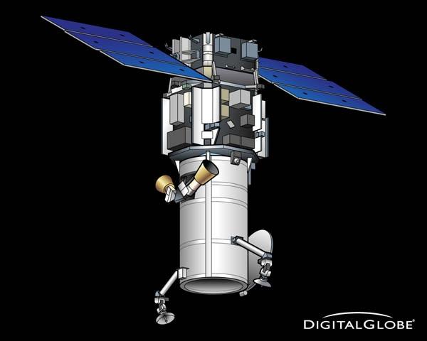
WorldView-2 (WV2) is a commercial imaging satellite of DigitalGlobe Inc. of Longmont, CO, USA (follow-on spacecraft to WorldView-1). The overall objective is to meet the growing commercial demand for high-resolution satellite imagery (0.46 cm Pan, 1.8 m MS at nadir - representing one of the highest available spaceborne resolutions on the market).
In the fall of 2003, DigitalGlobe had received a contract from NGA (National Geospatial-Intelligence Agency) of Washington DC to provide high-resolution imagery from the next-generation commercial imaging satellites. The contract award was made within NGA's NextView program. The NGA requirements called for imagery with a spatial resolution of 0.5 m panchromatic and 2 m MS (Multispectral) data. 1)
Spacecraft
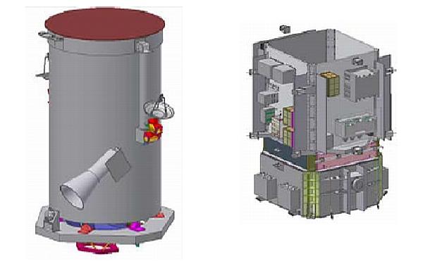
Like its Worldview-1 predecessor, the WorldView-2 spacecraft is being manufactured at BATC (Ball Aerospace and Technologies Corporation) of Boulder, CO which was awarded a contract in late 2006. BATC is providing its BCP 5000 (Ball Commercial Platform 5000) spacecraft bus for WorldView-2 and will integrate the remote sensing instrument onto the bus ( with WorldView-2, a larger imaging payload is being mounted onto the same spacecraft bus as that used for WorldView-1). A new vibration isolation system is being used on WorldView-2 for the payload to control jitter induced by the spacecraft. The BCP-5000 bus provides state-of-the-art power, stability, agility, data storage and data transmission (over the BCP-2000 bus). 2) 3) 4)
The spacecraft is 3-axis stabilized. The ADCS (Attitude Determination and Control Subsystem) employs star trackers, SIRUTM (Space Inertial Reference Unit- scalable) of Northrop Grumman, and GPS for attitude sensing, and CMGs as actuators for highly responsive pointing control. A spacecraft body-pointing range of ±40º about nadir is provided corresponding to a FOR (Field of Regard) of 1355 km in cross-track. An instantaneous geolocation accuracy of ≤ 500 m is provided at any start and stop of an imaging sequence. With its improved agility, WorldView-2 acts like a paintbrush, sweeping back and forth to collect very large areas of multispectral imagery in a single pass. WorldView-2 alone has a collection capacity of 975,000 km2/day. The combination of WorldView-2's increased agility and high altitude (770 km) enables it to typically revisit any place on Earth in 1.1 days.
The QuAD (Quiet Array Drive) motion control technology of Starsys Inc. is being used to articulate the solar arrays. The low disturbance implementation permits imaging observations to be conducted in parallel to the array articulation task.
A single-board BAE Systems RAD750 radiation-hardened computer manages the data processing command and control functions for WorldView-2.
S/C bus type | BCP-5000 |
S/C stabilization | - 3-axis stabilized using star trackers and solid-state IRU for sensing |
Pointing accuracy | - Accuracy: <500 m at image start and stop |
FOR (Field of Regard) | 1355 km in cross-track (nominally ±40º off-nadir body pointing capability |
S/C bus size | 4.3 m (height) x 2.5 m (diameter), 7.1 m span width (deployed) |
S/C launch mass, power | 2800 kg, 3.2 kW (EOL, 100 Ah NiH2 battery) |
Mission design life | 7.25 years |
Onboard data storage | 2.2 Tbit in solid-state memory with EDAC (Error Detection and Correction) |
The advanced CMGs (Control Moment Gyroscopes) provided by Ball Aerospace for WorldView-2, as well as for DigitalGlobe's WorldView-1, afford the satellites the flexibility to capture more imagery than ever before. This high-performance technology provides acceleration up to 10 times that of other attitude control actuators and improves both maneuvering and targeting capability, while reducing slew time from over 60 seconds to only 9 seconds to cover 300 km. This means WorldView-2 will be able to rapidly swing precisely from one target to another, allowing extensive imaging of many targets, as well as stereo, in a single orbital pass.
BATC used the M-95 CMG configuration for the WorldView-1 and WorldView-2 spacecraft providing a torque of up to 6.1 Nm. The M-95 CMG configuration has a total mass of 261.6 kg (including isolation mounts and electronics) and a power consumption of 220 W. 5)
CTIF (Command Interface Formatter Module): CTIF was developed at SwRI (Southwest Research Institute), San Antonio, TX. On WorldView-2, a redundant pair of CTIF modules provides complete uplink and downlink telemetry processing. The CTIF modules represent a continuation of SwRI's long track record of providing highly reliable spaceflight electronics supporting CCSDS's (Consultative Committee for Space Data Systems) command and telemetry protocols. The CTIF module is unique in that it provides significant hardware capabilities to offload traditional command and telemetry processing from the main spacecraft computer and to provide those core capabilities even if the main computer should go offline. 6)
RF communications: The command data are in S-band at 2 or 64 kbit/s. The housekeeping telemetry and tracking is being done in X-band at 4, 16, or 32 kbit/s of real-time data, or 524 kbit/s of stored data. The imagery is downlinked in X-band at 800 Mbit/s (dual polarization). The spacecraft provides a data storage capacity of 2.2 Tbit in solid state memory with EDAC (Error Detection and Correction). A total of 331 Gbit of imagery per orbit may be collected.
In addition, direct (real-time) downlinks to customer sites are available using the same high-speed 800 Mbit/s X-band link.
Launch
Launch: The WorldView-2 spacecraft was launched on October 8, 2009 on a Delta 7920 vehicle of ULA (United Launch Alliance) from VAFB, CA. ULA provided the services for this mission on behalf of BLS (Boeing Launch Services). 7) 8)
Orbit: Sun-synchronous nearly circular orbit, altitude = 767 km, inclination = 97.8º, period = 100.2 minutes, LTDN (Local Time on Descending Node) is at 10:30 hours.
Mission Status
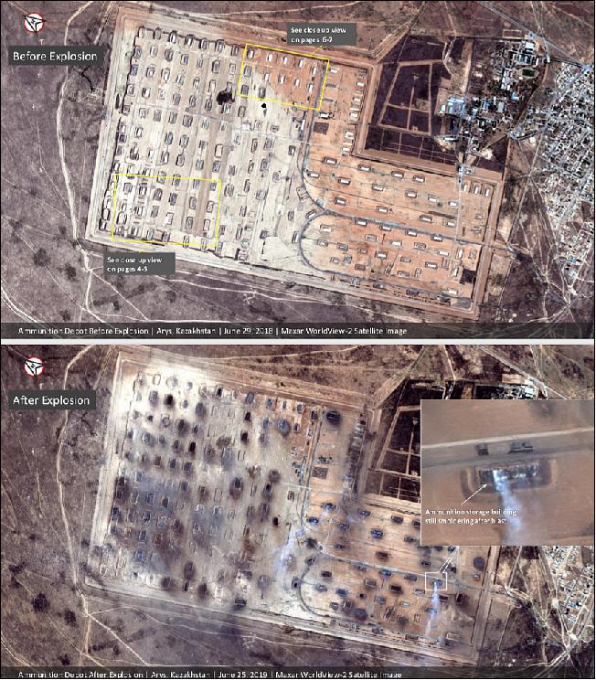
• June 26, 2019: Satellite photos supplied by Maxar of before and after reveal a dramatic explosion, and subsequent fire, of an ammunition depot in Arys, Kazakhstan that killed two, injured at least 46 and required the forced evacuation of tens of thousands. 9)
- Maxar collected new satellite imagery yesterday (25 June 2019) of the aftermath of a large ammunition depot explosion that occurred on June 24 near the Kazakhstan city of Arys. Maxar's satellite imagery reveals extensive damage to the facility as well as evidence that the blast widely scattered burning debris across fields and the nearby city.
- The cause of the fire has not yet been determined. Authorities say a criminal probe has been launched, with President Kassym-Jormart Tokayev pledging that those responsible would be "prosecuted under the law." Tokayev visited the region late on Monday, meeting with some injured residents.
- Small fires are still burning within the destroyed depot. According to press reports, Kazakhstan's Emergency Situations Committee said the blast occurred at around 9:20 a.m. following the outbreak of a fire at the military base. The explosion at the depot near the town of Arys in southern Kazakhstan's Turkestan region was the fourth such incident in the last decade.
- The governor of Turkestan, Umirzak Shukeyev, announced a state of emergency on Monday and the state ordered the evacuation of Arys' population of 45,000. At this time there is no information regarding whether the residents will be allowed to return to their homes as the danger of unexploded ammunition that could have been thrown from the explosion could turn a community into a minefield.
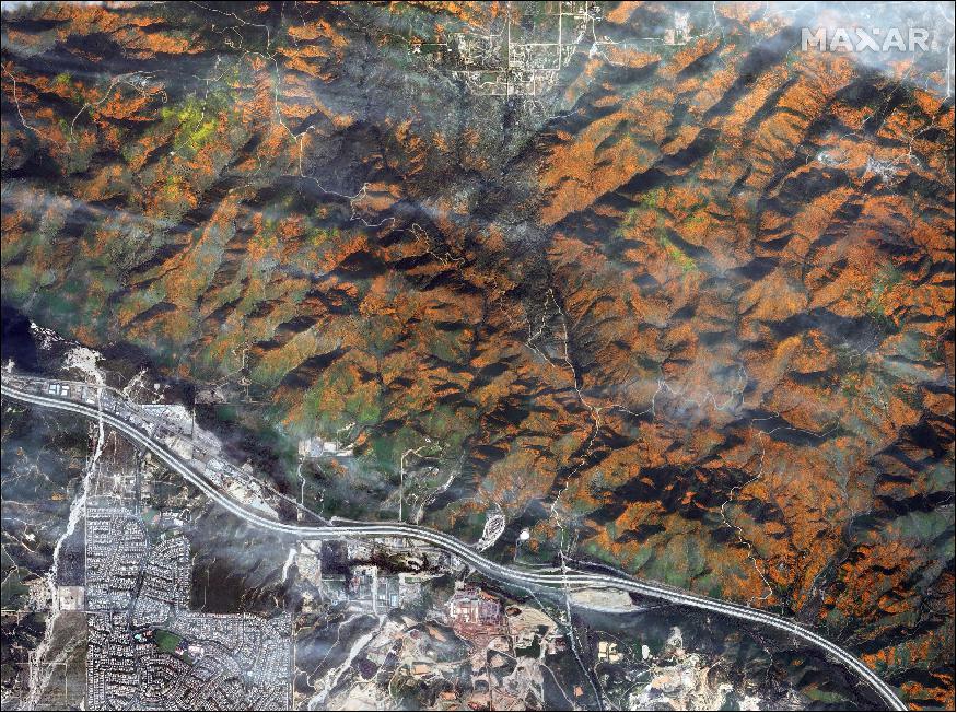
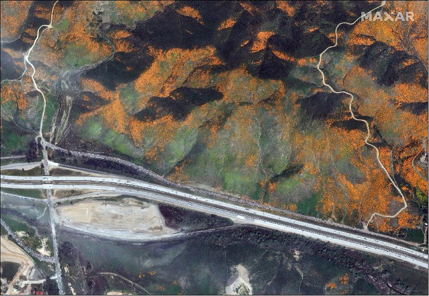
• March 20, 2019: Over the past month, the just-right combination of ample rain from December and stable cooler temperatures arrived in Walker Canyon, which is about 50 miles southeast of Los Angeles. This triggered a "super bloom" of dazzling orange poppy flowers that the area typically sees only once every 10 years. 10)
- Hordes of tourists have since descended upon the nearby city of Lake Elsinore, filling the roads with traffic and stuffing the hillsides with people who are trying to get a perfect Instagram selfie with the flowers.
- Meanwhile in space, the bursts of orange color — and miles' worth of cars — are so dense that the WorldView-2 satellite owned by DigitalGlobe easily spotted the scene from about 480 miles (770 km) above the planet.
- "DigitalGlobe collected a new set of images yesterday (March 19) of the 'Superbloom' near Lake Elsinore, California," a company representative told Business Insider in an email. "The colorful satellite imagery shows the hillsides along Walker Canyon filled with blooming poppies as well as hundreds of cars parked nearby and people hiking along trails in the area."
Acquisition of DigitalGlobe by MDA
• October 5, 2017: MDA (MacDonald, Dettwiler and Associates Ltd.) of Richmond, BC, Canada, a global communications and information company providing technology solutions to commercial and government organizations worldwide, today announced it has completed its acquisition of DigitalGlobe, Inc. ("DigitalGlobe"), the global leader in high resolution Earth imagery and information about our changing planet. The merger creates the leading integrated commercial provider of satellites, imagery and geospatial solutions to commercial and government customers worldwide. The newly combined company will offer a broader set of space-based solutions, increased scale and a more diversified revenue base.
New Corporate Name: MDA also announced today that it will become Maxar Technologies Ltd., and its U.S.-headquartered operating company, SSL MDA Holdings, Inc., will become Maxar Technologies Holdings Inc. The new Maxar Technologies launches a distinctive group of leading space brands, technologies and capabilities.
Canada-based MDA and U.S.-based DigitalGlobe overcame an extended review by the Committee on Foreign Investment in the United States (CFIUS) after refiling merger paperwork in July. The inter-agency committee, which reviews potential national security risks from foreign buyers of American businesses, ultimately found no issue with the merger.
MDA Corp.'s president and chief executive Howard Lance stated: "Maxar Technologies encompasses four of the leading commercial space technology brands—SSL, MDA, DigitalGlobe and Radiant—and represents the expanded benefits and value we will offer to our customers, shareholders, partners and employees."
With the addition of DigitalGlobe and Radiant Solutions, the Maxar Technologies portfolio of best-in-class brands offers a full suite of end-to-end solutions capabilities with deep domain expertise and space heritage.
- SSL: the leading commercial provider of communications and Earth observation satellites and scientific mission spacecraft for commercial and government markets
- MDA: an internationally recognized leader in space robotics, satellite antennas and subsystems, surveillance and intelligence systems, defense and maritime systems and geospatial radar imagery
- DigitalGlobe: the global leader in high resolution optical satellite imagery and information about our changing planet; and
- Radiant: a highly specialized provider of geospatial data, analytics, software and services to facilitate insights and intelligence where and when it matters most.
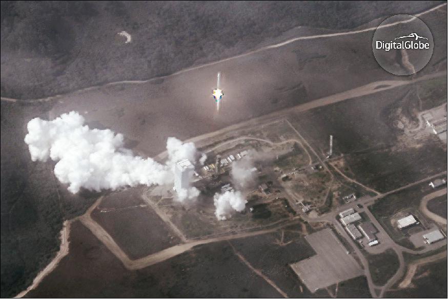
The WorldView-2 spacecraft is operational in 2017 in its 8th year on orbit. The image of Figure 9 was provided by DigitalGlobe on Feb. 3, 2017. 13) 14)
- DigitalGlobe released the WorldView-2 image to commemorate the milestone of "WorldView-4 operations start" — showing how the ULA (United Launch Alliance) Atlas 5 blasted off with WorldView-4 on Nov. 11, 2016 from Vandenberg Air Force Base, California.
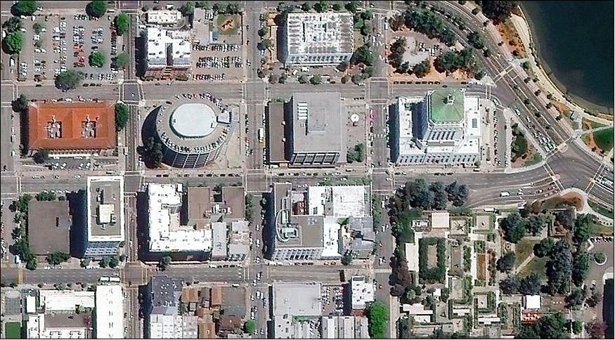
• July 19, 2016: According to the USAF (US Air Force), a DigitalGlobe imagery satellite was involved in what has been described as a debris-causing event. DigitalGlobe released an hours-old photo of Oakland, CA on July 19 (Figure 10), hoping to squash questions about the operability of one of its high-resolution imagery satellites after the U.S. Air Force said it had been part of a debris-causing event earlier in the day. -WorldView-2 offers 46 cm resolution imagery to both government and commercial customers. 15)
- JSpOC (Joint Space Operations Center), which is the Defense Department's nerve center for space operations and tracks space objects from Vandenberg Air Force Base in California, tweeted on July 19 that it had identified a debris-causing event related DigitalGlobe's WorldView-2 satellite. — As a result, the JSpOC is tracking eight pieces of debris related to the incident. An estimated time of the event was not immediately available.
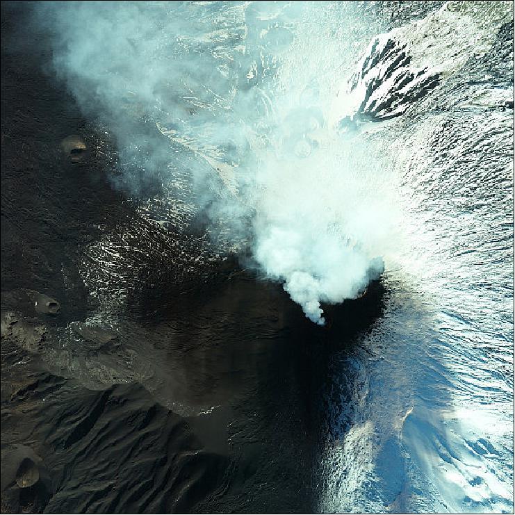
• December 4, 2015: Mount Etna showed its colors on 3 December erupting again just after 2 UTC for the first time since May 2015. The spectacular upwards jet of lava from the Voragine crater lasted for 50 minutes sending an ash plume more than 3 km high. The fountain of lava is said to have reached 1 km above the crater. This was the biggest eruption since September 1999 when the volcano shot volcanic material more than 12 km high. 16)
- Etna is the tallest and largest volcano of Europe and has four summit craters. Its eruptions occur both at the top and from its sides down to a few hundred meters above the sea-level. It is one of the most active volcanoes on the Earth so is continuously monitored by the Etna Observatory based in Sicily.
• April 28, 2015: DigitalGlobe, Inc. today announced the general availability of its Basemap +Vivid product for the entire African continent. Keeping pace with the rapid evolution of mapping technology, this is the first time that a complete, consistent satellite imagery base layer with 50 cm ground resolution has been available for Africa. 17)
- Many parts of Africa have never been mapped at this resolution from space, and never before has there been a complete imagery base map of Africa with this resolution from space, and never before has there been a complete imagery base map of Africa with this level of detail. While 50 cm satellite imagery for Africa has been available since 2008, it previously only covered smaller areas of interest.
- This Africa base map strives to maximize consistency and completeness of the imagery, aligning to DigitalGlobe's A3C quality program. Whether zoomed out to view an entire country, or zoomed in all the way down to view local vegetation, dwellings, and infrastructure, the imagery looks the way a user expects the Earth's surface to look. This uniformity helps local governments or global development agencies to build out maps and value-added information layers such as road vectors or population polygons for the people they serve. For web-enabled mapping platforms and location-based applications, users will stay immersed in their experience and not be distracted by inconsistencies in the imagery.
- "This is an important accomplishment in response to requests from our customers to create a verifiable, authoritative base map covering the entire continent," said Hyune Hand, DigitalGlobe's Senior Vice President for Product Marketing and Management. "Demand continues to grow, fueled by both regional projects and programs that require consistent quality coverage of an entire country."
- DigitalGlobe was in a unique position to develop this product with the world's most advanced constellation of commercial imaging satellites and six years' worth of sub-50 cm archive imagery. Not only does DigitalGlobe have the largest and most comprehensive archive of commercial satellite imagery for source data, but the research and development teams have invented and patented algorithms to process imagery at an unmatched speed and scale. Now prospective imagery users do not have to tackle the challenges of building a large imagery mosaic - such as inconsistencies between images, misalignment, visible seam lines, color imbalances, seasonality, haze, and cloud cover - to have a country-wide imagery layer on which to build the next generation of maps and applications.
• Feb. 26, 2015: DigitalGlobe today announced the signing of a MOU (Memorandum of Understanding) with the United Nations. Under the MOU, DigitalGlobe and UNOOSA ( United Nations Office for Outer Space Affairs) will take stock of their combined expertise in the use of Earth observation technologies for economic, social, and scientific development and improved decision-making, particularly in developing countries. 18)
- "DigitalGlobe is thrilled to partner with UNOOSA, the United Nations body that promotes international cooperation in the peaceful uses of outer space," said Jeffrey R. Tarr, DigitalGlobe President and Chief Executive Officer. "The arrangement provides an ideal platform to explore how high resolution satellite imagery and geospatial analytics can be more efficiently and effectively shared across the entire United Nations System, thus propelling us toward our purpose of Seeing a better world™."
- UNOOSA and DigitalGlobe will work to develop an online platform to provide easy access to imagery catalogues as well as data and analytical services specifically tailored for the needs of the United Nations. Under the agreement, DigitalGlobe will provide advisory services on remote sensing imagery and geospatial analytics, working with UNOOSA to advance and accelerate adoption of geospatial and satellite imagery-based analytics across the entire United Nations System. The cooperation will also extend to DigitalGlobe's participation in relevant UNOOSA-supported events and activities, including those of the United Nations Platform for Space-based Information for Disaster Management and Emergency Response (UN-SPIDER) and of the United Nations Geographic Information Working Group (UNGIWG).
• Dec. 18, 2014: DigitalGlobe has reported that, as a result of its annual satellite life review, the company will extend the useful lives of two of its satellites: WorldView-1 and WorldView-2. WorldView-1 will be extended by 2.5 years to 13 years, a 24% lifespan improvement, and WorldView-2 will be extended two years to 13 years, an 18% lifespan improvement. 19) 20)
- WorldView-1, which was originally expected to reach its end of life in the second quarter of 2018, is now expected to reach end of life in the fourth quarter of 2020.
- WorldView-2, which was originally expected to reach its end of life in the fourth quarter of 2020, is now expected to reach end of life in the fourth quarter of 2022.
• In June 2014, DigitalGlobe announced that it received notice from the U.S. Department of Commerce (DOC) on its application to allow the company to sell its highest-quality and industry-leading commercial satellite imagery. Effective immediately, DigitalGlobe will be permitted to offer customers the highest resolution imagery available from their current constellation. Additionally, the updated approvals will permit DigitalGlobe to sell imagery to all of its customers at up to 0.25 m panchromatic and 1.0 m multispectral ground sample distance (GSD) beginning six months after its next satellite WorldView-3 is operational. WorldView-3 is scheduled to launch, August 13 , 2014 from VAFB (Vandenberg Air Force Base), CA. 21) 22)
- Two of DigitalGlobe's satellites, GeoEye-1 and WorldView-2 , collect imagery sharper than 0.50 m, and all customers will have access to that imagery at the highest native resolution. WorldView-3 will provide even higher resolution at 0.31 m, and the GeoEye-2 satellite, which is substantially complete, will capture similarly sharp images when it is launched to replace a satellite currently in service or as an expansion to the constellation once warranted by market demand.
Parameter | Ikonos-2 | QuickBird-2 | WorldView-1 | GeoEye-1 | WorldView-2 | WorldView-3 | GeoEye-2 |
Spectral characteristics | Pan+4 MS | Pan+4 MS | Pan | Pan+4 MS | Pan+8 MS | Pan+8 MS +8 SWIR | Pan+4 MS |
Panchromatic resolution (nadir) | 0.82 m | 0.55 m | 0.50 m | 0.41 m | 0.31 m | 0.31 m | 0.31 m |
Multispectral resolution (nadir) | 3.28 m | 2.20 m | N/A | 1.64 m | 1.84 m | 1.24 m | 1.24 m |
Accuracy specification (nadir) | 9 m CE90 | 23 m CE90 | 4 m CE90 | 3 m CE90 | 3.5 m CE90 | 3.5 m CE90 | 3.5 m CE90 |
Onboard storage capacity | 80 Gbit | 128 Gbit | 2199 Gbit | 1000 Gbit | 2199 Gbit | 2199 Gbit | 3000 Gbit |
Collection capacity/day | 150,000 km2 | 160,000 km2 | 1,500,000 km2 | 350,000 km2 | 1,200,000 km2 | 680,000 km2 | 680,000 km2 |
Launch date | Sept. 24, 1999 | Oct. 18, 2001 | Sept. 18, 2007 | Sept. 06, 2008 | Oct. 08, 2009 | Aug. 13, 2014 | 2016 |
• The WorldView-2 spacecraft and its payload are operating nominally in 2014, in its 5th year on orbit.
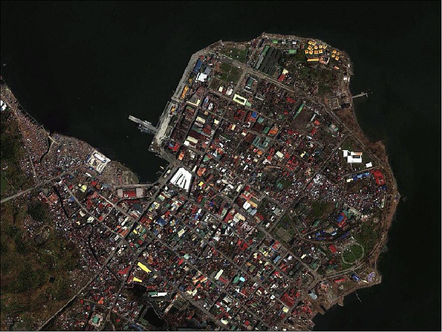
• November 2013: Typhoon Haiyan, also known as Typhoon Yolanda in the Philippines, was a powerful tropical cyclone that devastated portions of Southeast Asia, particularly the Philippines, on November 8, 2013. It is the deadliest Philippine typhoon on record, killing at least 6,268 people in that country alone. Haiyan is also the strongest storm recorded at landfall, and unofficially the strongest typhoon ever recorded in terms of wind speed. 23)
There was widespread devastation from the storm surge in Tacloban City especially in San Jose, with many buildings being destroyed, trees knocked over or broken, and cars piled up. The low-lying areas on the eastern side of Tacloban city were hardest hit, with some areas completely washed away (90%of the city had been destroyed) . Flooding also extended for 1 km inland on the east coast of the province. The WorldView-2 spacecraft observed the region on Nov. 13, 2013 (Figure 12).
• The WorldView-2 spacecraft and its payload are operating nominally in 2013. - The image of Figure 13 was featured on the Earth from Space video program (Earth observation image of the week) of ESA on Sept. 26, 2013. 24)
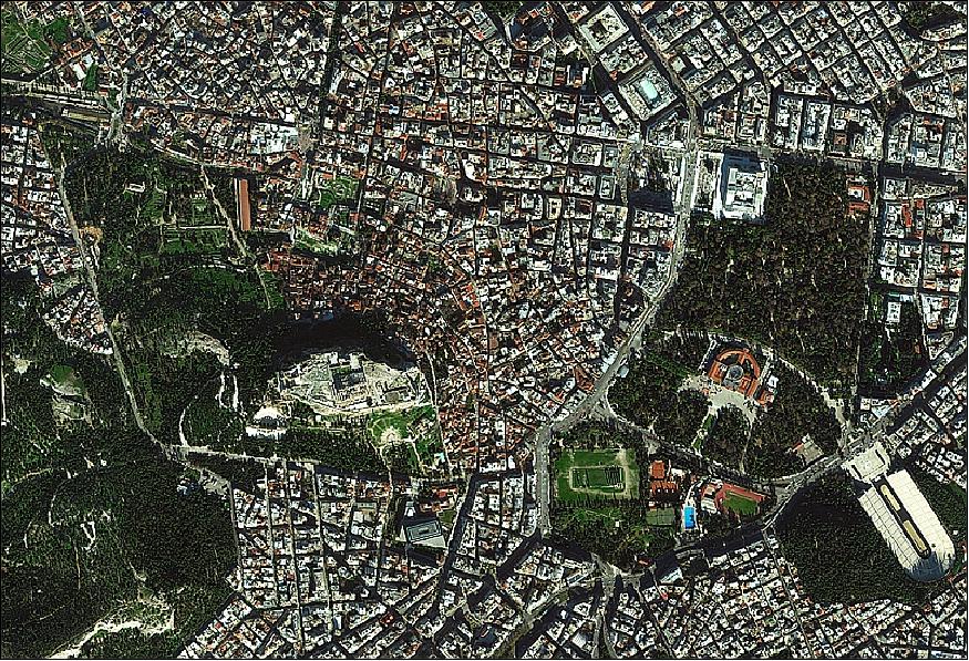
Legend to Figure 13: The image shows the center city of Athens, the capital and largest city of Greece. Near the center of the image is the famous Acropolis of Athens – standing high about the surrounding city as evident by the shadow to the north. Nearby to the southeast is the Temple of Zeus, with shadows from the remaining standing columns stretching across the grass. Further northeast are the National Gardens surrounding the Zappeion building. At the upper left corner of the gardens is the Greek parliament building, overlooking Syntagma Square. In the lower-right corner one can see the large, white marble Panathenaic Stadium, originally built for the athletics part of the Panathenaic Games – in honor of the goddess Athena – it has been rebuilt, enlarged, excavated and refurbished over the centuries. In 1896, it hosted the first modern Olympic Games, which saw over 240 athletes from 14 nations.
• The WorldView-2 spacecraft and its payload are operating nominally in 2012. 25)
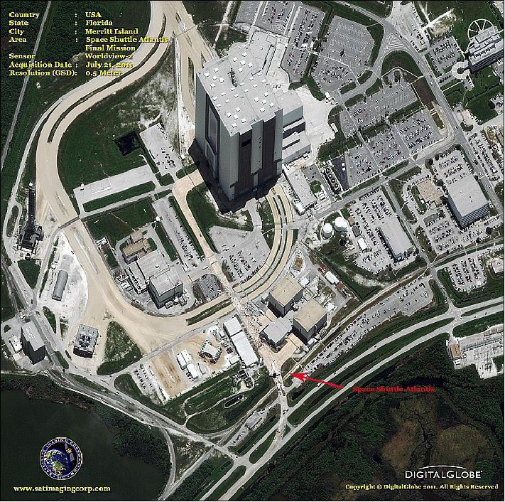
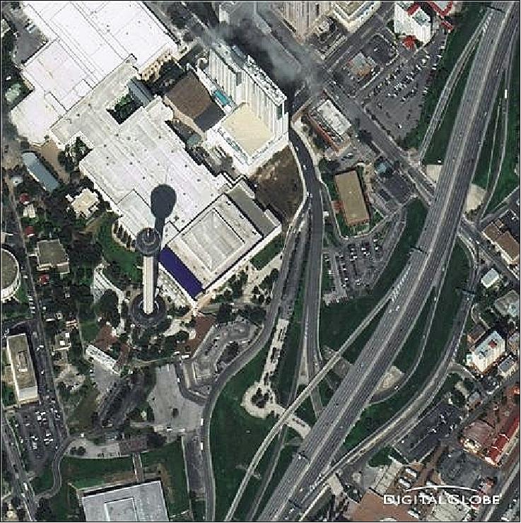
• The spacecraft and its payload are operating nominally in 2011. Figure 15 is an example of the spacecraft's event monitoring capability. DigitalGlobe is supporting this crisis/event monitoring service on a regular basis. 27) 28)

|
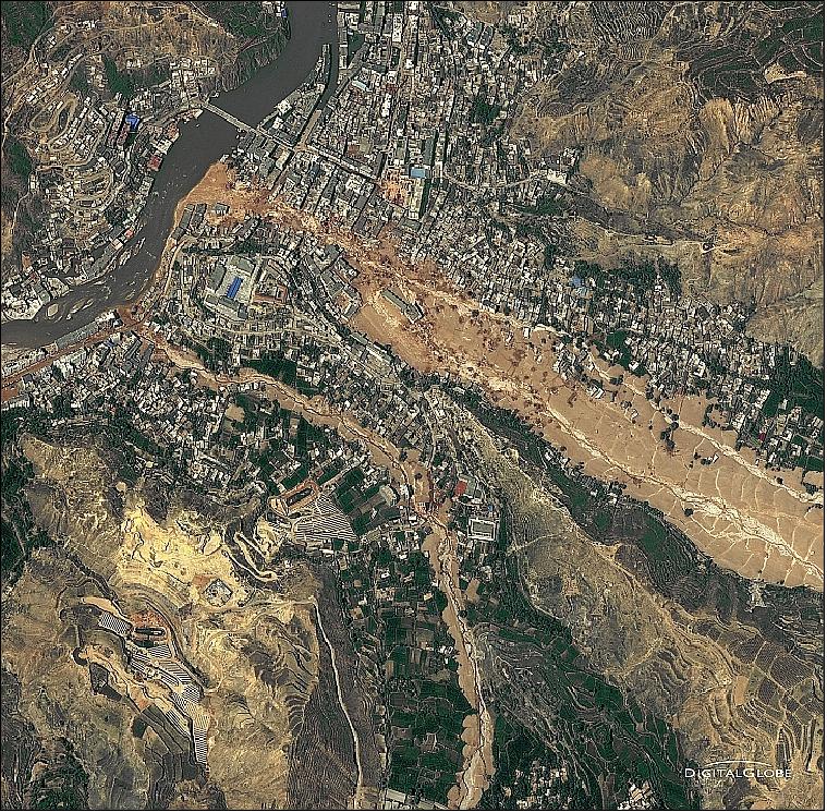
Legend to Figure 16: Around midnight on Aug. 8, 2010, a violent surge of loosened earth roared down mountain slopes and slammed into quietly sleeping neighborhoods in Zhouqu County in Gansu, China. The catastrophic mudslides - the deadliest in decades according to state media - buried some areas under as much as 7 m of suffocating sludge. 1,765 people died. Property damages totaled an estimated $759 million.
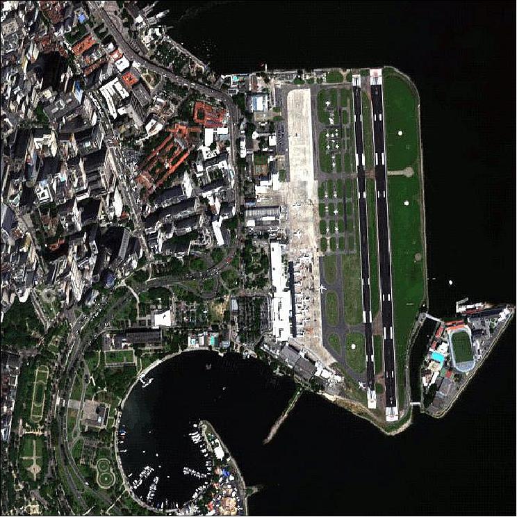
• The WorldView-2 spacecraft and its payload are operating nominally in 2010. 32) 33) 34)
• For the Haiti earthquake disaster which occurred on January 12, 2010, DigitalGlobe is providing a free-of-charge high-resolution imagery service to aid the extensive relief and recovery efforts.
• On January 4, 2010, DigitalGlobe reported that its spacecraft WorldView-2 has achieved full operational capability and that its imagery is now commercially available. 35) 36)
• The DigitalGlobe ground station received a downlink signal confirming that the satellite successfully separated from its launch vehicle and automatically initialized its onboard processors. WorldView-2 is currently undergoing a calibration and check-out period. DigitalGlobe expects imagery products and services from WorldView-2 to be commercially available in approximately 90 days. 38)
Sensor Complement
WV110 (WorldView-110 camera)
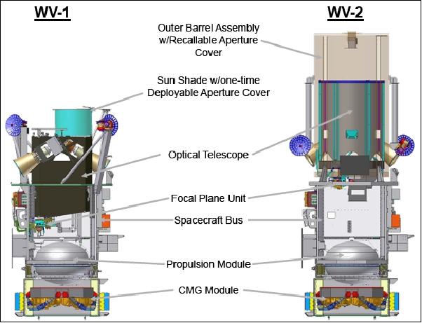
WV110 was designed and developed at ITT Corporation's Space Systems Division of Rochester, NY. The objective of the WV110 instrument is to provide high-resolution panchromatic as well as 8-band multispectral imagery for enhanced mapping and monitoring applications (including stereo imagery due to rapid retargeting capability). 39) 40)
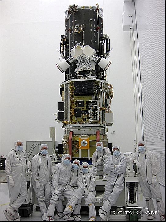
In September 2008, BATC started with the integration of the WV110 camera. On Feb. 24, 2009 the WV110 camera had been integrated into the WorldView-2 spacecraft and system-level testing has commenced. 41) 42) 43) 44)
Imager type | Pushbroom imager (or a line scan imaging system) | |
Imaging mode | Panchromatic (Pan) | Multispectral (MS) 8 bands |
Spectral range | 450-800 nm | 400-450 nm (coastal blue) |
Spatial resolution at nadir | 0.46 m GSD (0.52 m at 20º off-nadir) | 1.8 m GSD (2.4 m at 20º off-nadir) |
Swath width | 16.4 km (multiple adjoining paths can be imaged in a target area in a single orbit pass due to S/C agility) | |
Detectors | Pan: Si CCD array (8 µm pixel size) with a row of > 35,000 detectors | |
Data quantization | 11 bit | |
Geolocation accuracy of imagery | ≤ 3 m (using a GPS receiver, a gyroscope and a star tracker) without any GCP (Ground Control Points) | |
Optics | TMA telescope with an aperture diameter of 1.1 m, focal length = 13.3 m, f/12 | |
TDI (Time Delay Integration) | 6 selectable levels from 8 to 64 in Pan and MS | |
FOV (Field of View) | > 1.28º | |
Instrument size | 3 m tall | |
Spectral band | Center wavelength (nm) | Minimum lower band edge (nm) | Maximum upper band edge (nm) |
Pan (WorldView-1) imager | 650 | 400 | 900 |
Pan (WorldView-2) imager | 625 | 447 | 808 |
MS1 (NIR1) | 831 | 765 | 901 |
MS2 (red) | 659 | 630 | 690 |
MS3 (green) | 546 | 506 | 586 |
MS4 (blue) | 478 | 442 | 515 |
MS5 (red edge) | 724 | 699 | 749 |
MS6 (yellow) | 608 | 584 | 632 |
MS7 (coastal blue) | 427 | 396 | 458 |
MS8 (NIR2) | 908 | 856 | 1043 |
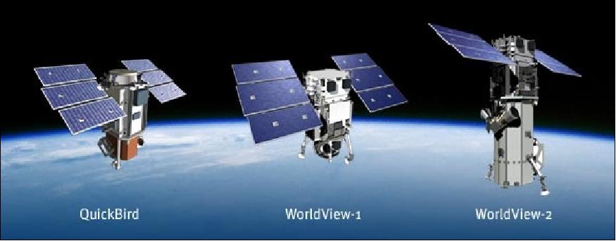
Parameter / Spacecraft | QuickBird-2 (QB) | WorldView-1 | WorldView-2 |
Launch date | Oct. 21, 2001 | Sept. 18. 2007 | Oct. 08, 2009 |
Orbital altitude (SSO) | 450 km | 450 km | 770 km |
Spacecraft mass at launch | 931 kg | 2500 kg | 2800 kg |
Spacecraft bus size | 3 m x 1.6 m Ø | 3.6 m x 2.5 m Ø | 4.3 m x 2.5 m Ø |
Spacecraft bus type | BCP-2000 | BCP-5000 | BCP-5000 |
Solar array span | 5.2 m | 7.1 m | 7.1 m |
Spacecraft power | 1.14 kW (EOL) single junction GaAs cells | 3.2 kW (EOL) triple junction GaAs cells | 3.2 kW (EOL) triple junction GaAs cells |
Battery | 40 Ah NiH2 | 100 Ah NiH2 | 100 Ah NiH2 |
Attitude actuation | Reaction wheels | CMG assembly | CMG assembly |
S/C body pointing capability | ±30º (nominal in any direction) | ±40º (nominal in any direction) | ±40º (nominal in any direction) |
Onboard propulsion | 4 x 4.4 N hydrazine thrusters | Yes | Yes |
Spacecraft design life | 5 years | 7.25 years | 7.25 years |
RF Wideband downlink | 320 Mbit/s | 800 Mbit/s | 800 Mbit/s |
Onboard data storage | 128 Gbit | 2.2 Tbit | 2.2 Tbit |
|
|
|
|
Payload (builder) | BHRC60 (BATC) | WV60 (ITT) | WV110 (ITT) |
Telescope aperture | 60 cm Ø | 60 cm Ø | 110 cm Ø |
Swath width | 16.5 km | 16.4 km | 16.4 km |
Pan resolution at nadir | 0.61 cm | 50 cm | 46 cm |
MS resolution at nadir | 2.4 m | - | 1.8 m (8 bands) |
Monoscopic area coverage | 1 x | > 4 x | > 4 x |
Single pass mono coverage | 1 strip of 350 km | 1 strip of 650 km | 1 strip of 650 km |
Single pass stereo coverage | Single scene (<10º off nadir track) | 3 strip x 55 km | 3 strip x 55 km |
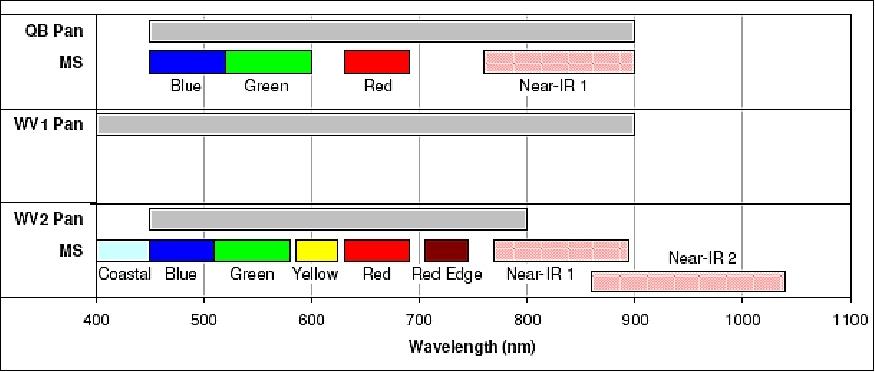
WorldView-2 is the first commercial satellite to carry a very high spatial resolution 8-band multispectral sensor. Focal planes on the WV2 sensors are enhancements over those used on QuickBird (QB). In addition to overall increased agility, the WV110 focal plane carried by WV2 has a total of one panchromatic and eight multispectral bands with center wavelengths at 425 (coastal blue), 480 (blue), 545 (green), 605 (yellow), 660 (red), 725 (red edge), 835 (NIR1), and 950 (NIR2) nm, respectively. 46)
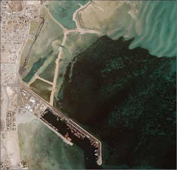
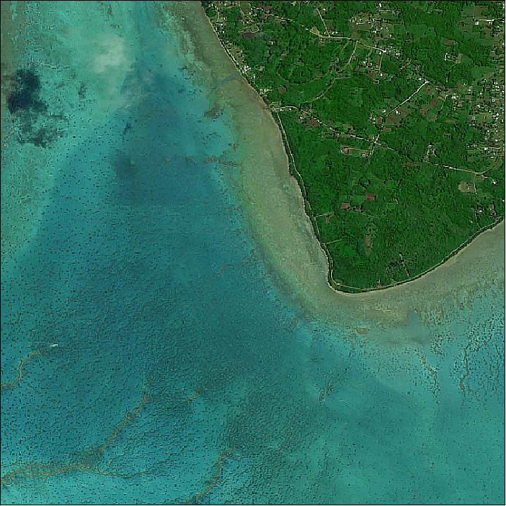
The new spectral dimensions in WV2 (coastal blue, yellow, rededge, NIR2) target costal and vegetation land cover types with applications in plant species identification, mapping of vegetation stress and crop types, mapping of benthic habitats, wetlands, coast water quality, and bathymetry. The addition of yellow and red edge bands fills important gaps in the spectrum that relate to our ability to capture vegetation phenomenology. The coastal and NIR2 bands extend the spectral coverage to wavelengths where there is increased divergence among the spectral response of vegetation types and many man-made materials. Overall, the broader and continuous coverage, along with sharper multispectral channels provide the potential for more robust modeling and discrimination of spectral signatures.
Mode | PAN line rate | MS line rate | Aggregation | TDI rates | Cmpression levels (bpp) |
A | 24,000 | N/A | PAN= 1 x 1 | PAN= 8, 16, 32, 48, 56, 64 | 2.75, 2.4 |
B | 24,000 | 3,000 | PAN= 1 x1 | PAN= 8, 16, 32, 48, 56, 64 | PAN: 2.75, 2.4 |
C | 20,000 | 5,000 | PAN= 1 x1 | PAN= 8, 16, 32, 48, 56, 64 | PAN: 2.75, 2.4 |
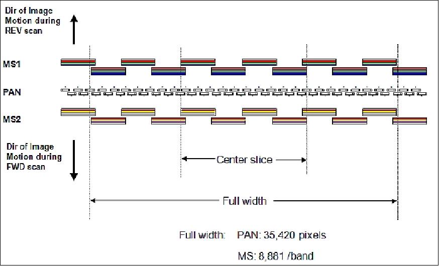
Note: the PAN and MS line rates stated in Table 9 are at pixel level, not at detector level.
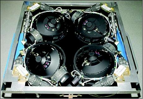
The focal plane is comprised of fifty panchromatic staggered DSAs (Detector Sub-Arrays), and two sets of ten MS, staggered DSAs, as shown in Figure 22. The two sets of staggered MS arrays are positioned on either side of the Pan array, one for the MS1 bands (MS1: NIR1, Red, Green, Blue), and the other for the MS2 bands (MS2: RedEdge, Yellow, Coastal, NIR2) . Each DSA contains four parallel rows of detectors, each with a different color filter. For each DSA, the individual bands are collected by a separate readout register. The Pan array uses two separate readout registers for each of its fifty DSAs. Each readout register has its own analog-to-digital converter.
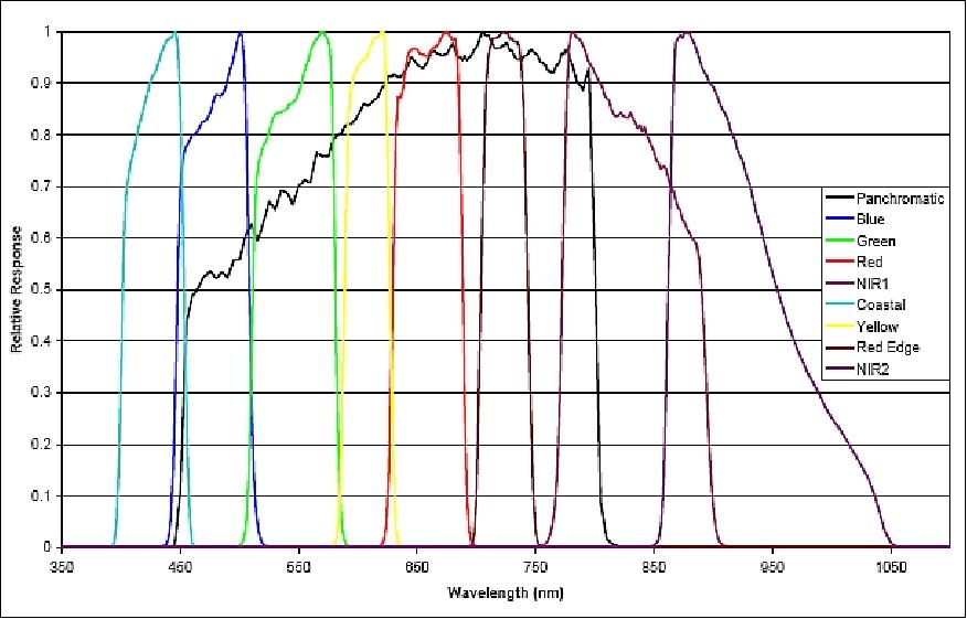
The WorldView-2 spectral radiance response is defined as the ratio of the number of photo-electrons measured by the system, to the spectral radiance [W m-2 sr-1 µm-1] at a particular wavelength present at the entrance to the telescope aperture. It includes not only raw detector quantum efficiency, but also transmission losses due to the telescope optics and MS filters. The spectral radiance response for each band is normalized by dividing by the maximum response value for that band to arrive at a relative spectral radiance response. These curves for the WorldView-2 panchromatic and MS bands are shown in Figure 23.
References
1) "Worldview-2 Earth Observation Satellite, USA," URL: http://www.aerospace-technology.com/projects/worldview-2/
2) http://www.ballaerospace.com/page.jsp?page=82
3) http://www.euspaceimaging.com/products/67/
4) "WorldView-2 Media Kit," BATC, URL: http://www.ballaerospace.com/page.jsp?page=211
5) R. C. Hopkins, C.L. Johnson, C. Kouveliotou, D. Jones, M. Baysinger, T. Bedsole, C.D. Maples, P. J. Benfield, M. Turner, P. Capizzo, L. Fabisinski, L. Hornsby, K. Thompson, J. H. Miernik, T. Percy, "Xenia Mission: Spacecraft Design Concept," NASA/MSFC, NASA/TM—2009–216270, Dec. 2009, p. 16, URL: http://ntrs.nasa.gov/archive/nasa/casi.ntrs.nasa.gov/20100019148_2010019690.pdf
6) "Southwest Research Institute (SwRI) 2009 News Release: WorldView-2 satellite features key processing electronics from SwRI," SwRI, Oct. 8, 2009, URL: http://www.swri.org/9what/releases/2009/WorldView2.htm
7) "United Launch Alliance Successfully Launches WorldView-2 Mission for DigitalGlobe & Boeing Launch Services," Oct. 8, 2009, URL: http://www.prnewswire.com/news-releases/united-launch-alliance-successfully-
launches-worldview-2-mission-for-dig
italglobe--boeing-launch-services-63791607.html
8) http://www.floridatoday.com/content/blogs/space/ULA_WorldviewII.pdf
9) "The Big Boom ... Maxar's Satellite Reveals Huge Ammunition Depot Explosion in Kazakhstan," Satnews Daily, 26 June 2019, URL: http://www.satnews.com/story.php?number=699489550
10) Dave Mosher, "Satellites just photographed California's dazzling 'super bloom' of spring flowers from outer space," Business Insider, 20 March 2019, URL: https://www.businessinsider.com/california-superbloom-spring-flowers-space-satellite-pictures-2019-3
11) "MDA Completes Acquisition of DigitalGlobe, Creates Industry Leader in Satellite Systems, Earth Imagery, Geospatial Solutions and Analytics," MDA Press Release, Oct. 5, 2017. URL: https://mdacorporation.com/news/pr/pr2017100509.html
12) Henry Caleb, "MDA closes DigitalGlobe merger, rebrands as Maxar Technologies," Space News, Oct. 5, 2017, URL: http://spacenews.com/mda-closes-digitalglobe-merger-rebrands-as-maxar-technologies/
13) https://twitter.com/DigitalGlobe
14) Justin Ray, "WorldView 4 high-resolution satellite now open for business in space," Spaceflight Now, Feb. 3, 2017, URL: http://spaceflightnow.com/2017/02/03/worldview-4-high-resolution-satellite-now-
open-for-business-in-space/
15) Mike Gruss, "DigitalGlobe says WorldView-2 operational after "debris causing event"," Space News, July 19, 2016, URL: http://spacenews.com/u-s-air-force-digitalglobes-worldview-2-involved-in-
debris-causing-event/
16) "Etna's newest plumes imaged by WorldView-2 satellite," European Space Imaging, Dec. 4, 2015, URL: http://us5.campaign-archive1.com/?u=afbe993ce225d71274b8f371b&id=4b32fc2966
17) "DigitalGlobe Produces the World's First Complete and Consistent High Resolution Satellite Imagery Base Map of Africa," DigitalGlobe, April 28, 2015, URL: [web source no longer available]
18) "United Nations, DigitalGlobe Sign Agreement to Collaborate on High-Resolution Satellite Imagery and Geospatial Solutions," DigitalGlobe, Feb. 26, 2015, URL: [web source no longer available]
19) "DigitalGlobe Extends Useful Lives of Two Satellites and Assigns Initial Life to WorldView-3," Digital Globe Press Release, Dec. 18, 2014, URL: [web source no longer available]
20) "The Lives Of Two Satellites Have Been Extended By DigitalGlobe," SatNews Daily, Dec. 22, 2014, URL: http://www.satnews.com/story.php?number=1994242207
21) "U.S. Department of Commerce Relaxes Resolution Restrictions DigitalGlobe Extends Lead in Image Quality," DigitalGlobe Press Releases, June 11, 2014, URL: [web source no longer available]
22) "US Dept of Commerce Relaxes Resolution Restrictions on DigitalGlobe," Space Daily, June 12, 2014, URL:
http://www.spacedaily.com/reports/US_Dept_of_Commerce_Relaxes_Resolution_
Restrictions_on_DigitalGlobe_999.html
23) "Typhoon Haiyan," Wikipedia, URL: http://en.wikipedia.org/wiki/Typhoon_Haiyan
24) "Earth from Space: City of Knowledge," ESA, Sept. 26, 2013, URL: http://www.esa.int/Our_Activities/Observing_the_Earth/Earth_from_Space_City_of_knowledge
25) "DigitalGlobe Incorporated Satellite and Aerial Program Update," Proceedings of the 11th Annual JACIE (Joint Agency Commercial Imagery Evaluation ) Workshop, Fairfax, Va, USA, April 17-19, 2012, URL: http://calval.cr.usgs.gov/wordpress/wp-content/uploads/Thomassie_
DigitalGlobe_JACIE_4_17_121.pdf
26) "WorldView-2 Satellite Images," Satellite Imaging Corporation, URL: http://www.satimagingcorp.com/gallery-worldview-2.html
27) Brett P. Thomassie, "DigitalGlobe Systems and Products Overview," 10th Annual JACIE ( Joint Agency Commercial Imagery Evaluation) Workshop, March 29-31, 2011, Boulder CO, USA, URL: http://calval.cr.usgs.gov/JACIE_files/JACIE11/Presentations/WedPM/
405_Thomassie_JACIE_11.143.pdf
28) Jianwei Tao, Wenxian Yu, "A Preliminary Study on Imaging Time Difference Among Bands of Worldview-2 and Its Potential Applications," 10th Annual JACIE ( Joint Agency Commercial Imagery Evaluation) Workshop, March 29-31, 2011, Boulder CO, USA, URL: http://calval.cr.usgs.gov/JACIE_files/JACIE11/
Presentations/WedPM/
315_Tao_JACIE_11.137.pdf
29) Byron Smiley, "Geolocation Accuracy Topics Relevant to DigitalGlobe's Satellite Constellation," 10th Annual JACIE ( Joint Agency Commercial Imagery Evaluation) Workshop, March 29-31, 2011, Boulder CO, USA, URL: http://calval.cr.usgs.gov/JACIE_files/JACIE11/Presentations/WedPM/
430_Smiley_JACIE_11.125+11.126.pdf
30) Paul C. Brennan, "Geolocation Accuracy Monitoring of High Resolution Commercial Imagery," 10th Annual JACIE ( Joint Agency Commercial Imagery Evaluation) Workshop, March 29-31, 2011, Boulder CO, USA, URL:
http://calval.cr.usgs.gov/JACIE_files/JACIE11/Presentations/
WedPM/115_Bresnahan_JACIE_11.008.pdf
31) Michael A. Taverna, "DigitalGlobe To Change WorldView-2 Orbit," Aviation Week, Sept. 20, 2010, URL:
http://www.aviationweek.com/aw/generic/story_generic.jsp?
channel=space&id=news/asd/2010/09/17/01.xml&headline=
DigitalGlobe%20To%20Change%20WorldView-2%20Orbit
32) Information provided by Charles P. Herring of DitigalGlobe Inc., Longmont, CO
33) "New Dimension in High Resolution Imagery," NRSC (National Remote Sensing Center) User Interaction Workshop, Hyderabad, India, Feb. 3-4, 2010
34) Philip Cheng, Chuck Chaapel, "WorldView-2 Satellite," GEO Informatics, June 2010, URL: http://www.pcigeomatics.com/pdfs/GeoInformatics_WorldView-2.pdf
35) "DigitalGlobe's WorldView-2 Reaches Full Operational Capability on Schedule," DigitalGlobe, January 4, 2010
36) DigitalGlobe's WorldView-2 Declared fully operational," Space News, January 11, 2010, p. 8
37) "Coastal Applications Using WorldView-2, Proceedings of JACIE 2010 (Joint Agengy Commercial Imagery Evaluation) Workshop, Fairfax, VA, USA, March 16-18, 2010, URL: http://calval.cr.usgs.gov/JACIE_files/JACIE10/Posters/Thomassie_Brett_4band_NIR.pdf
38) DigitalGlobe Announces the Successful Launch of WorldView-2," GEOICT Oct. 8, 2009, URL: http://geoict.yorku.ca/news/digitalglobe-announces-the-successful-launch-of
39) "The Benefits of the 8 Spectral Bands of WorldView-2," WorldView, Aug. 2009, URL: http://worldview2.digitalglobe.com/docs/WorldView-2_8-Band_Applications_Whitepaper.pdf
40) http://desms.com/downloads/digitalglobe-brochures/36-dgworldview-
2featureclassdatasheeta4/download.html
41) "Ball Aerospace Begins Integration of WorldView-2 Imaging Instrument," BATC, Sept. 3, 2008, URL: http://www.pressreleasepoint.com/ball-aerospace-begins-integration-
worldview2-imaging-instrument
42) Todd Updike, Chris Comp, "Radiometric Use of WorldView-2 Imagery," DigitalGlobe Technical Note, Nov. 1, 2010
43) D. Poli, E. Angiuli, F. Remondino, "Radiometric and Geometric Analysis of WorldView-2 Stereo Scenes," ISPRS, Commission I, WG I/4, 2010, URL:
http://www.isprs.org/proceedings/XXXVIII/part1/03/03_04_Paper_188.pdf
44) "WorldView-2 Satellite Sensor," Satellite Imaging Corporation, URL:
http://www.satimagingcorp.com/satellite-sensors/worldview-2.html
45) Brett Thomasie, "DigitalGlobe update," Proceedings of JACIE 2007 (Joint Agency Commercial Imagery Evaluation), Fairfax, VA, USA, March 20-22, 2007, URL: http://calval.cr.usgs.gov/JACIE_files/JACIE07/Files/19Thomas.pdf
46) G. Marchisio, F. Pacifici, C. Padwick, "On the relative predictive value of the new spectral bands in the WorldView-2 sensor," Proceedings of IGARSS (IEEE International Geoscience and Remote Sensing Symposium) 2010, Honolulu, HI, USA, July 25-30, 2010
The information compiled and edited in this article was provided by Herbert J. Kramer from his documentation of: "Observation of the Earth and Its Environment: Survey of Missions and Sensors" (Springer Verlag) as well as many other sources after the publication of the 4th edition in 2002. - Comments and corrections to this article are always welcome for further updates (eoportal@symbios.space).
Spacecraft Launch Mission Status Sensor Complement References Back to top